
Cross-Component Issue Metamodel and Modelling Language
Sandro Speth
1
, Steffen Becker
1
and Uwe Breitenb
¨
ucher
2
1
Institute of Software Engineering, University of Stuttgart, Universit
¨
atsstr. 38, 70569 Stuttgart, Germany
2
Institute of Architecture of Application Systems, University of Stuttgart, Universit
¨
atsstr. 38, 70569 Stuttgart, Germany
Keywords:
Issue Management, Integration, Component-based Architecture, Bug Tracking, Modelling Language.
Abstract:
Software systems are often built out of distributed components developed by independent teams. As a result,
issues of these components, such as bugs or feature requests, are typically managed in separate, isolated issue
management systems. As a result, it is hard to keep an overview of issues affecting issues of other compo-
nents. Managing issues in a component-specific scope comes with significant problems in the development
process since managing such cross-component issues is error-prone and time-consuming. Therefore, the cross-
component issue management system Gropius was developed in previous work, which is a tool for integrated
cross-component issue management that acts as a wrapper across the independent components’ issue manage-
ment systems. This paper introduces the underlying metamodel of Gropius in detail and presents the graphical
modelling language implemented by Gropius.
1 INTRODUCTION
Modern systems consist of various independent com-
ponents composed and integrated to form a new ap-
plication system, e.g., microservices. Often the com-
ponents are individual applications that are managed
as individual projects. Thus, their software issues,
such as bug reports or feature requests, are managed
in different issue management systems (IMS) (also
called bug tracker). Typical issue management sys-
tems are GitHub, Gitlab, Jira, and Redmine. How-
ever, this makes it hard to keep the overview if an
issue affects multiple other components managed in
different issue management systems. For example, if
a bug in one component crashes another component
due to a dependency. Thus, this would lead to two
bug reports in two different issue management sys-
tems, one for each component, although one of them
is just a result from the other. However, if this is man-
aged in different issue management systems, nobody
has the chance to see this. Mahmood et al. identi-
fied in their systematic literature survey, ten signif-
icant problems and challenges in such component-
based systems (Mahmood et al., 2015). One of the
challenges mentioned is a lack of adequate bug track-
ing across the overall architecture. Other challenges
are the interdependence of the components, and a lack
of efficient task allocation, which can hold many dif-
ferent parties over time. As a result, managing is-
sues in such systems is both error-prone and time-
consuming (Speth, 2019; Speth et al., 2020). Ad-
ditionally, since issues for multiple components are
managed independently, it is hard to keep an overview
of the issues across the entire application system that
is built out of multiple components whose issues are
managed independently. Furthermore, communica-
tion is difficult as usually multiple teams are involved.
Due to the distribution of the total application’s issue
management, fast access to the dependencies of is-
sues is not possible. Therefore, this paper presents
(i) the Gropius Cross-Component Issue Metamodel,
which is a formal metamodel for cross-component
issues, and (ii) the Gropius Cross-Component Issue
Modelling Language, which is a graphical modelling
language that can be used to model and describe
issues that have dependencies with issues in other
individually managed components. We developed
the metamodel based on requirements gathered in an
expert survey (Speth, 2019). We implemented the
metamodel and the graphical modelling language in
the open-source Gropius (Speth et al., 2020) tool.
Gropius is a tool for managing cross-component is-
sues in a cognitive effective way while acting as a
wrapper over conventional issue management sys-
tems such as Jira. Gropius currently does not support
the complete cross-component issue metamodel, i.e.
various types of links between issues, links from is-
sues to artefacts, and non-functional constraints for
304
Speth, S., Becker, S. and Breitenbücher, U.
Cross-Component Issue Metamodel and Modelling Language.
DOI: 10.5220/0010497703040311
In Proceedings of the 11th International Conference on Cloud Computing and Services Science (CLOSER 2021), pages 304-311
ISBN: 978-989-758-510-4
Copyright
c
2021 by SCITEPRESS – Science and Technology Publications, Lda. All rights reserved
issues. In previous work (Speth et al., 2020), we
presented an initial idea of cross-component issues
in a demonstrator prototype. However, we neither
presented the cross-component issue metamodel nor
the graphical modelling language in details but only
the high-level ideas of both. Therefore, in this paper,
we contribute a concrete definition of the metamodel
for cross-component issues that we extend with ad-
ditional features and a concrete and complete defini-
tion of the graphical modelling language for cross-
component issues. Additionally, we present the meta-
model of the graphical modelling language now. In
contrast to the metamodels previously implemented
in Gropius, we not only present details but also ex-
tended them regarding the following features: (i) sup-
port for bidirectional issue relation links, (ii) linking
from issues to artefacts links, and (iii) non-functional
constraints for the issues’ content. Additionally, we
extend the Gropius’ GraphQL API and frontend to
implement filter mechanisms for various issues to
further improve the usability of the Gropius Cross-
Component Issue Modelling Language (GML).
The remainder is structured as follows: sec-
tion 2.2 describes background and problem statement
for issue management in component-based architec-
tures. Afterwards, section 3 briefly outlines the Cross-
Component Issue Modelling Language (GML). The
abstract syntax of the GML is described in section 4.
Furthermore, section 5 describes the concrete graphi-
cal syntax of the GML in detail. A prototype of an is-
sue management system which implements the GML
is presented in section 6. Finally, the related work is
surveyed in section 7 and we conclude in section 8.
2 BACKGROUND & PROBLEM
STATEMENT
This section describes background, motivation, and
problem statement for our research questions.
2.1 Background
Modern software architectures often follow a dis-
tributed architectural style in which various indepen-
dently developed, maintained and deployed compo-
nents are combined to form larger systems (Szyperski
et al., 2002). The components form software mod-
ules specified by contracts, which other components
can use via their defined interfaces (Reussner et al.,
2016). Components are usually developed and main-
tained by single individual teams. As these teams are
often third-party teams, these components’ ownership
does not belong to the developers of depending com-
Order Service
Shipping Service
Payment Service
Figure 1: Example of a component-based webshop.
ponents. Therefore, components can be deployed and
used without understanding the internals, e.g. by us-
ing a docker image. However, in the overall architec-
ture, dependencies between the independent compo-
nents arise through the components’ interaction.
Since each component is developed indepen-
dently, teams are often free to choose their technol-
ogy stack (Newman, 2015; Nygard, 2007). This free-
dom of choice also includes the choice of the issue
management system or bug tracking system, to man-
age feature requests, bug reports and other types of
issues. Examples of issue management systems in-
clude GitHub, Gitlab, Jira and Redmine. In the scope
of our work, we define an issue as follows: An issue
is a documentation that provides crucial information
about the source code or models it is related to (Bet-
tenburg et al., 2008)(Sommerville, 2011, p. 744-745).
We see increasingly often that systems are composed
of several individually managed components, and as
a result, the respective issues are managed in inde-
pendent issue management systems. However, track-
ing, communicating, and managing issues across is-
sue management systems is reaching its limits.
2.2 Motivating Scenarios
Let’s consider a simple webshop that is implemented
as microservice architecture with three microservices:
(1) an order service, (2) a shipping service and (3) a
payment service as depicted in fig. 1. Each service
is developed by an independent team. Additionally,
each microservice has its issues stored in an individ-
ual issue management system and source code stored
in an individual repository system. The microservices
are connected as depicted. Suppose the order service
depends on an API of the shipping service. We will
look at three use cases for this project.
Use Case ”Issue Propagation”. Assume the func-
tional interface of the shipping service’s interface is
updated without coordination between all affected
teams. However, the update contains a bug, e.g. the
implementation of one of the service’s updated op-
erations does not conform to its functional API con-
tract. If the order service calls the updated operation,
the bug might affect the order service’s functionality.
Therefore, the issue can propagate to another compo-
nent. If this deployment happens at runtime without
coordination as propagated by modern processes like
Cross-Component Issue Metamodel and Modelling Language
305

DevOps, then at runtime even the order service might
fail. Whereas in the past, often only one project was
developed, today, with these numerous dependencies
on other services and the uncertainty of how often
these are deployed, the uncertainty of when errors
might occur has increased dramatically. Although the
teams typically write e-mails to each other as found
out in an industry expert survey (Speth, 2019), typi-
cal problems are that after a short time nobody might
read them because they come in a frequency that can-
not be processed without support. Since the order ser-
vice’s development team does not have the ownership
of the shipping service’s source code, they cannot fix
their bug themselves. As a result, they have to create
an issue in the shipping service’s issue management
system. Nevertheless, the issue for the order service
should be documented as well.
Use Case ”Issue Synchronization”. Next, consider
a similar example where two components depend on
the payment service’s interface and, therefore, the is-
sue would be propagated to both dependent compo-
nents. The resulting issues of order service and ship-
ping service components are semantically equivalent.
However, as both components manage their issues
in different issue management systems, the issue in-
stances cannot be the same. Therefore, a change in,
e.g. the order service’s issue, has to be propagated
to the shipping service’s issue. However, as no issue
management system technology supports such propa-
gation across issue management system boundaries,
teams need to find a way of synchronizing the is-
sues. Here, often e-mails or business messengers are
used (Speth, 2019), but no dedicated tooling.
Use Case ”Linking to Other Component’s Inter-
faces”. In the last use case, we focus on a new func-
tional interface for an API endpoint of the shipping
service. The order service has to be adapted to use
the newly developed interface feature of the shipping
service. Therefore, a feature request for the order ser-
vice component is created. However, developers need
to know how the new interface looks like they have
to adapt to resolve the feature request. A description
using only the issues’ text body is hard to understand
and might be not complete. As a result, linking the
issue to the interface description of the new endpoint
of the shipping service would provide an excellent ad-
vantage for the issue’s description and comprehensi-
bility. However, the shipping service’s source code
and artefacts are stored in a different repository sys-
tem than the source code and artefacts of the order
service. Thus, linking an issue to an artefact of an-
other component is impossible due to the bound of
an issue management system’s project with a compo-
nent’s source code repository.
2.3 Problems of the Scenarios
While there are tools that allow issues to be managed
from multiple components or synchronised across
components, such as the Jira plug-ins Backbone Is-
sue Sync (K15t, 2020) and Multi Project Picker (Bro-
ken Build, 2020), these only work within the same
issue management system vendor (Speth et al., 2020).
However, due to the distributed architecture and mod-
ern microservice and DevOps approaches, each team
can choose its own desired technology stack (New-
man, 2015; Nygard, 2007). This results in the fact that
such a component-based architecture often manages
its issues in many independent issue management sys-
tems from different vendors. Existing tools do not
provide the functionality required regarding manag-
ing issues across multiple components developed by
different teams. As a result, managing such issues re-
quires complicated communication, as several inde-
pendent teams may be involved.
In the third use case, an issue should link to an
artefact from another component. However, in state-
of-the-art issue management systems, such links are
only possible within the system as an additional prop-
erty or as a URL in the issue’s body. Quick access to
such artefact dependencies of other components with
clear semantic representation is not possible. A fur-
ther problem is the representation of issues that af-
fect several components in existing tools. A repre-
sentation in a concrete textual syntax, as developers
are currently used to from all state-of-the-art systems,
is well suited for issues of individual components.
However, as soon as an issue affects several compo-
nents, or is dependent on an issue of another com-
ponent, this can only be represented poorly in tex-
tual terms which means that quick access to the is-
sues on which the issue is dependent is not possible.
Often important information is lost or can be easily
overlooked if other components are involved. One
reason for this is that the current textual representa-
tions do not consider the overall architecture of the
system. In the usual tools, such as Jira or GitHub,
this is always a project-specific scope in the sense of
an issue management system project. However, to
effectively present cross-component issues, a cross-
project or cross-component scope of the issue man-
agement system is required without having to migrate
the existing applications to a new issue management
system. Additionally, a representation of such cross-
component issues requires the inclusion of the over-
all systems’ architecture to gain a cross-component
scope instead of a single-component scope and model
the cross-component influence of an issue in a clear
and comprehensible way.
CLOSER 2021 - 11th International Conference on Cloud Computing and Services Science
306
2.4 Research Questions
Based on the previous section, we can identify the
problem that issues can propagate across several com-
ponents. An issue must, therefore, be created in the
affected components and refer to the respective pre-
ceding issue. As usually components of a component-
based architecture store their issues in different issue
management systems, there is no support for integrat-
ing with other issue management systems to link to
other issues of different components. Furthermore, a
simple URL in the issue’s description, which links to
the other issue is not a qualitative solution. Therefore,
our first research question is:
RQ 1 ”How to relate dependencies between is-
sues of different components where each com-
ponent is developed by an individual team and,
therefore, has its issues managed in its own issue
management system?”
From the second use case, we identified that an issue
should be annotated with additional metadata, such as
artefact links or non-functional constraints, to provide
better context for the processing of the issue. As a
result, our second research question is:
RQ 2 ”How should an issue be linked to arte-
facts, e.g. source code, of other components and
how should non-functional constraints be anno-
tated to an issue to model, e.g. service-level ob-
jectives?”
A presentation of cross-component issues in a con-
crete textual syntax is not optimal. Much informa-
tion, such as the affected components or the issues on
which a dependency originate, cannot be presented
in a cognitively effective manner. As soon as other
components and issues of other components are af-
fected, this information can only be displayed in the
description text of the issue instead of its attributes
due to the project-specific scope of a conventional is-
sue management system. Additionally, information
such as the affected components of the linked issues
can easily be overseen. This results in textual infor-
mation overload for the human mind and a lack of
clarity. Therefore, the third research question is:
RQ 3 ”How does one model cross-component
issues, where the model also reflects the archi-
tecture and issue’s dependencies to issues of
other components, in a cognitive effective way?”
These three research questions provide the basis
for our approach of modelling and managing cross-
component issues.
JSON
{;}
0..*
Gropius Cross-Component Issue Metamodel
(GMM) (Abstract Syntax in UML)
Gropius Cross-Component Issue
Concrete Textual Syntax (GTS)
(in JSON for automated Processing)
Gropius Cross-Component Issue
Modelling Language (GML)
(Concrete Graphical Syntax as
Visual Graph for User)
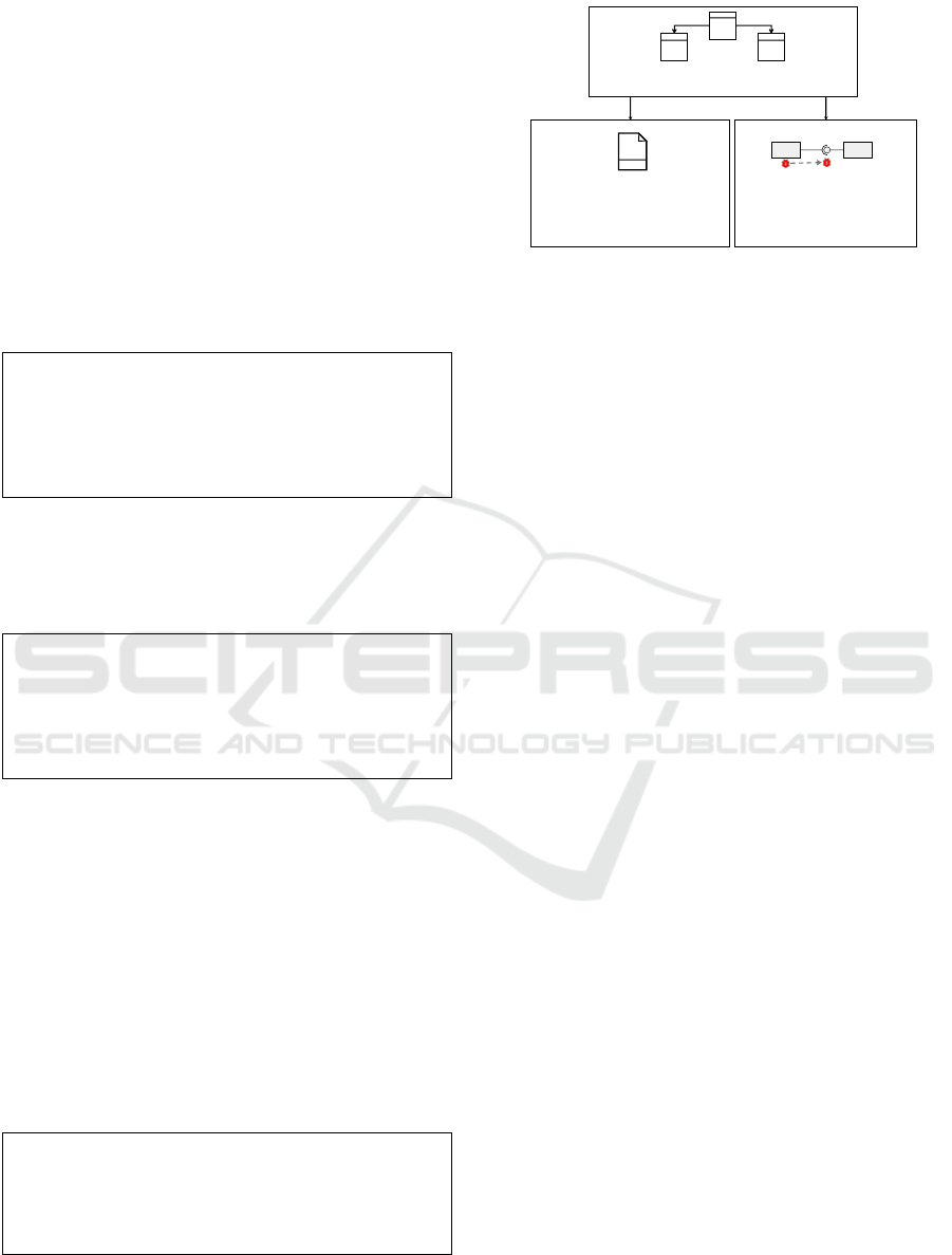
Figure 2: Overview of the abstract and concrete syntaxes.
3 OVERVIEW OF THE GML
This section provides an overview of the Gropius
Cross-Component Issue Metamodel (GMM) as the ab-
stract syntax of cross-component issues, as well as the
concrete syntaxes (1) the Gropius Cross-Component
Issue Modelling Language (GML), which is a con-
crete graphical syntax for the easily understandable
representation of cross-component issues, and (2) the
Gropius Concrete Textual Syntax (GTS) for machine
processing. The overview is presented in fig. 2.
Although standard issue management systems
such as Jira, and GitHub differ in the metamodel of
their issues concerning various features, basic com-
monalities can still be found, such as a title and text
body as shown by Speth (Speth, 2019). One of the
main problems of conventional issues is that they only
have one component they can affect and, therefore,
are stored in this component’s issue management sys-
tem. Thus, the affected component influences the is-
sues’ location. Multiple locations cannot be repre-
sented without additional plugins, e.g. Multi Project
Picker (Broken Build, 2020), or alienation of features,
e.g. having an additional issue management project
for cross-component issues and adding URL links to
the issues of each component in the description of the
mutual issue. For further details, see section 7. The
Gropius tool implements a basic metamodel for cross-
component issues, such as cross-component assign-
ing to multiple locations (components or interfaces),
direct semantic links to other issues of the same or
another component, e.g. in the case of dependency
relationships. However, this has not been published,
and in the demonstrator paper of Gropius (Speth et al.,
2020) only the high-level ideas are described. As the
Gropius Cross-Component Issue Metamodel (GMM)
provides the basis for our GML, we present the meta-
model in detail in this work and extend it to the fol-
lowing features. Additional features presented in this
work are the possibility of modelling non-functional
conditions, e.g. for service-level objectives, and link-
Cross-Component Issue Metamodel and Modelling Language
307

ing issues to artefacts of different components. Ad-
ditionally, the relationships between issues are ex-
tended so that dependency relationships are modelled
in both directions. Hence, the extensions can address
a couple of the challenges identified by Mahmood et
al. (Mahmood et al., 2015), see section 2.1.
From this abstract syntax, this work derives two
concrete syntaxes, the GTS which is a concrete tex-
tual syntax in JSON that is machine-readable and can
be processed by Gropius or other systems, and the
GML which is a concrete graphical syntax, to model
cross-component issues more comprehensibly for hu-
mans (cf. section 5). While the concrete textual
syntax models cross-component issues in JSON, the
GML’s concrete graphical syntax abstracts the mod-
elling of cross-component issues with additional com-
ponents, such as folders for each issue type (Bug Re-
port, Feature Request, Unclassified), to provide more
context to the user in an understandable visual way.
4 THE GROPIUS
CROSS-COMPONENT ISSUE
METAMODEL
This section presents the metamodel which forms the
abstract syntax for cross-component issues, and there-
fore, the basis for the Gropius Cross-Component Is-
sue Modelling Language.
4.1 Research Design of the Metamodel
To gain a better understanding of cross-component
issues in real-world scenarios and to create a meta-
model, initial expert interviews were conducted at
the beginning of this work. Developers, DevOps
engineers, project managers and software architects
from various companies of different sizes were in-
terviewed. In the course of the interviews, prob-
lems of issues that affect several independently de-
veloped components were identified, as they are also
described by Mahmood et al. in their systematic lit-
erature review (cf. section 2.1). Various characteris-
tics of such cross-component issues were noted. Fur-
thermore, the experts were asked what measures they
take in their daily development processes to deal with
these problems and what features they would like to
see in the management of cross-component issues.
Subsequently, issue metamodels of well-known issue
management systems were analyzed. Based on this,
we identified a minimal metamodel for issues and ex-
tended it to describe cross-component issues, taking
into account the expert interviews’ findings.
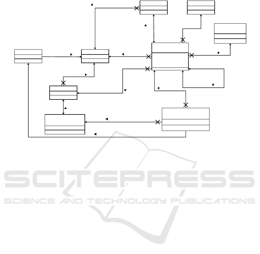
4.2 Details of the Metamodel
The metamodel for cross-component issues is shown
in fig. 3. Gropius (Speth et al., 2020) implements this
metamodel. However, the corresponding demonstra-
tor paper only describes the ideas on a high-level ba-
sis without going into details. Like common issues, a
cross-component issue contains a title and body text
to detail the issue’s concern, e.g., problem statement.
There are other commonly supported features for an
issue, such as labels consisting of a name and colour
to classify the problem the issue is about and a list
of developers as assignees which should solve the is-
sue. A developer is developing at least one compo-
nent which is affected by the issue. In addition to this,
a cross-component issue supports all other commonly
used information. For example, it has a status if it is
open or closed. For the sake of brevity, we show only
the details required for understanding our approach.
The entities of the metamodel are written in italics.
Cross-Component Issue. In contrast to a common
issue, a cross-component issue can concern multi-
ple different components in a component-based or
service-oriented architecture. Instead of replicating
the issue to each component’s issue management sys-
tem and creating a technical debt due to these clones,
it should be the same issue for every component.
This approach allows changes in the issue’s body to
be recognized by all component’s developers. How-
ever, as current issue management systems cannot
share an issue with other issue management systems, a
cross-component issue management system as wrap-
per above these systems is needed to manage cross-
component issues (cf. section 6). To enable track-
ing in which issue management system an issue is
stored, we also include the issue management system
and cross-component issue management system.
While managing the same issue in several compo-
nents is rarely used, it is much more common for an
issue to propagate through interfaces of one compo-
nent to other components. In such a case, it could be
better to create an individual (cross-component) issue
for each component describing the resulting problem
and link to origin issues along the propagation chain.
Therefore, this concept extends the issue’s metamodel
to provide semantic links to other issues for depen-
dencies or other kinds of relations. As a result, depen-
dencies between issues can be represented directly.
Thus, a link is not only a URL, but the linked issue
is directly integrated into the actual cross-component
issue. As a result, a developer can see both the de-
pendencies on another issue and the contents of the
linked issue immediately.
CLOSER 2021 - 11th International Conference on Cloud Computing and Services Science
308
Component
Developer
linkedToIssues
1..*
0..*
links to
CrossComponent
Issue
- title: string
- textBody: string
- isOpen: boolean
assigned to
assignees
assignedIssues
0..*
0..*
0..*
1..*
Concerned
Components
representedIssues
concerns
develops
1..*
1..*
Developed
Components
developer
{uniq.}
{unique}
{unique}
{unique}
{unique}
{unique}
IssueManagement
System
storedIssues
is connected to
1..*
issueRootLocations
concerns
0..*
1
concernedComp.
{unique}
CrossComponentIssue
ManagementSystem
Issue
0..*
1
{unique}
stored in
1
manages
0..*
1
location
managedIssues
0..*
1..*
{unique}
represents
{unique}
{uniq.}
{unique}
{uniq.}
{unique}
NonFunctional
Constraints
linkedByIssues
{unique}
0..*
constraints
0..*
Project
0..*
1..*
consists of
manages
1
{unique}
{unique}
projects
components
0..*
{unique}
projects
issueManagementSystem
Artefact
documents
0..*
{unique}
0..*
artefacts
Figure 3: Metamodel for Cross-Component Issues.
Non-functional Constraints. To improve the Qual-
ity of Service (QoS) properties of the components
to be developed, this work introduces the possibil-
ity of specifying non-functional constraints for issues.
These constraints do not refer to the issue itself, but
the content described by the issue. For example, a
feature request can have one or more non-functional
constraints, such as an average response time or other
service level objectives (SLOs), that must be met for
the feature request to be considered fulfilled. For eas-
ier machine processing of such constraints by differ-
ent systems, e.g. CICD tools, it is advantageous to
store these constraints as an extra property of an issue
instead of keeping them unstructured in the text body
and having to interpret it. Furthermore, a template
language for the constraints can be applied, for exam-
ple, an SLO language such as WSLA (Keller and Lud-
wig, 2003), to make the SLOs machine-interpretable.
Artefact Links. To link an cross-component issue
to artefacts, e.g. source code, such artefact links can
be explicitly specified. In this way, a developer can
obtain the context he needs to solve the issue. Unlike
artefact links in traditional issue management sys-
tems, the linked artefacts of cross-component issues
can belong to different components than the issue it-
self. An issue can link several artefacts, and an arte-
fact can be linked by several cross-component issues.
5 THE GROPIUS
CROSS-COMPONENT ISSUE
MODELLING LANGUAGE
(GML)
This section describes the Gropius Cross-Component
Issue Modelling Language (GML).
5.1 Metamodel of the GML
The metamodel for the GML is shown in fig. 4 and de-
scribes the relationship between the shapes and lines
of the elements of the GML and their meaning.
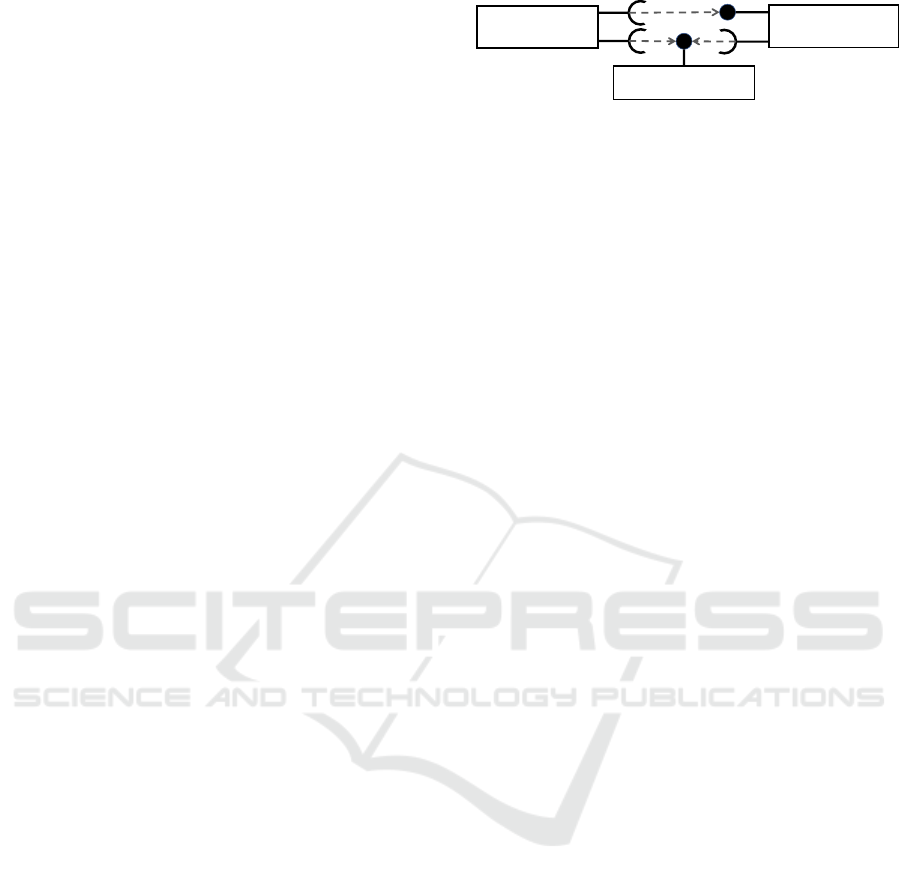
Components are represented in the GML as
rounded rectangular shapes (label 1 in fig. 4). The
component shapes contain the display name of the re-
spective component. Furthermore, components can
be connected via interfaces. These interfaces are rep-
resented similar to the lollipop notation of interfaces
in UML component diagrams. A component can pro-
vide an interface, which is represented by a circle
shape (label 2.1 in fig. 4). Suppose another compo-
nent consumes such a provided interface. In that case,
the component’s shape is connected to a half-circle
shape (label 2.2) that stands for consumption of the
interface. Both, the shape for an interface and the
shape for the interface’s consumption are adjacent.
The shapes of the component is connected by a line
to the interface or the consumer, which was omitted
Cross-Component Issue Metamodel and Modelling Language
309
RoundedRectangle
Shape
ConsumingInterface
Shape
CircularShape
FolderShapeDashedArrow
FRFolder
BugReport
Folder
Unclassified
Folder
1
0..*
provider
consumer
component
comp.
comp.
1
0..*
0..*
providedInterface
issueFolder
0..3
0..3
1
1interface
issueFolder
1
1
origin
target
1
1
1
2.2
2.1
3.1
3.2
4
Group
0..*
1
group
0..3
1
Figure 4: The metamodel of the GML.
in fig. 4 for reasons of space and clarity.
The (cross-component) issues are collected in
folders in the GML to ensure clarity when dealing
with large numbers of issues. The folders are rep-
resented as folder shapes (labels 3.1 and 3.2) and are
located next to the components or interfaces to which
the issues belong, as in fig. 5. There are three types
of folder shapes, one for each category of an issue in
Gropius, namely bug report, feature request and un-
classified. A component shape or interface shape can
have up to one issue folder shapes from each cate-
gory. Multiple components can be grouped in a group
which results in grouping the issues of all grouped
components per category. Dashed arrows show the
relationships between the issues (label 4). One such
line goes from the folder in which the outgoing is-
sue is assigned to the folder in which the target issue
is located. If several issues from one folder relate to
one or more issues from another folder, the relation-
ship shapes are also collected. A number extends the
dashed line to indicate the number of issue relations.
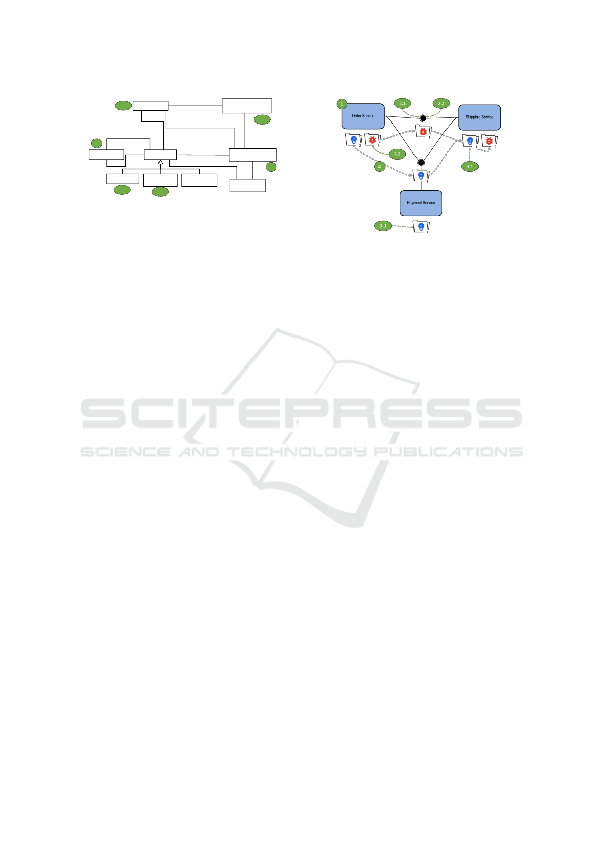
5.2 Visual Rendering of the GML
Figure 5 shows the example project of section 2.2 in
GML. There are several bug reports and feature re-
quests for the three services and their interfaces. The
issues are, in some cases, dependent on each other.
For example, a bug of the shipping service propagates
via the service’s interface to the order service. In total,
three independent bug reports are created.
This example contains all relevant shapes and
lines of GML. Components are shown in coloured
rectangles with rounded corners (label 1) to make
them easily recognisable and quickly distinguishable
from issue folders. In a lollipop notation of the in-
terfaces (labels 2.1 and 2.2), the components are con-
nected to each other. Multiple consumers merge their
half-circle shape together. The issue folders (labels
3.1 and 3.2) are close to the components or interfaces
but can be moved to one of the four sides. Addition-
ally, dashed arrows represent relationships between
issues of different components (label 4) which are dis-
played in a semi-transparently way so that they do not
Figure 5: An example Gropius project in GML notation.
interfere with a component if it is crossed. Showing
the issues’ dependencies as arrows allows propaga-
tions across multiple components to be quickly de-
tected and root issues to be identified. The categories
of issues are distinguished in the folders in two ways,
firstly by the symbol (blue lamp for feature requests,
red beetle for bug reports, black question mark for
unclassified), and secondly by the colour. Each folder
has a small number of the issues it contains. When
selecting an issue folder in the Gropius frontend, the
incoming and outgoing issue relation links are marked
with different colours. This colour marking makes it
easy to identify the relevant links in the component,
even with a large number of issue relation links. All in
all, the GML offers a cross-component view, although
some detailed information remains hidden as a result
without further clicks when used in a tool. Which is-
sues are actually in a folder, for example, can only be
found out by clicking on the component or the folder.
6 PROTOTYPE
The Gropius prototype (Speth et al., 2020) serves as a
wrapper over existing issue management systems to
model and manage cross-component issues. In the
context of this work, Gropius was extended with the
features of the concrete syntaxes as described in sec-
tion 1, i.e. dependency links are stored bi-directional,
non-functional constraints, and artefact links. While
the concept of grouping exists in the GML, this is not
implemented in Gropius yet. However, an attempt
was made to counteract this with a minimap and zoom
mechanisms until the grouping is implemented. Ad-
ditionally, we extended the Gropius frontend to offer
many filtering options to improve large projects’ over-
all clarity with many components and issues. Further-
more, if issue relations are hidden, and a folder with
incoming or outgoing relations has hovered over, the
issue’s relations are shown in the frontend.
CLOSER 2021 - 11th International Conference on Cloud Computing and Services Science
310

7 RELATED WORK
Besides Gropius, there are no scientific approaches to
manage cross-component issues. However, there are
some industrial efforts in grey literature which we are
explaining in the following.
Several forums of the well-known issue manage-
ment systems Jira and Redmine describe scenarios
where cross-project (in the sense of issue manage-
ment system projects) issues exist and need to be
managed. In the answers, several approaches are
discussed, which are possible with the respective
providers. In a Redmine forum
1
, it is suggested to
use one (Redmine) task for all projects and to cre-
ate a corresponding subtask for each affected project.
Since this solution requires all software projects to
manage their issues in the same Redmine project, this
approach is not sufficient for component-based sys-
tems where each component manages its issues in a
separate issue management system’s project.
Similar to the proposed Redmine solution, two
Atlassian forum posts
23
describe three Atlassian Jira
plugins. With the Structure plugin data from several
projects can be managed and filtered in a spreadsheet-
like UI. However, contributor rights are required for
each project. The plugins Backbone Issue Sync (K15t,
2020) and Multi Project Picker (Broken Build, 2020)
are more suitable for component-based architectures
as they support multiple Jira projects. The Back-
bone Issue Sync enables the synchronization of an
issue across multiple Jira projects. Similarly, the
Multi Project Picker allows managing an issue across
projects by removing the limitation that an issue can
only belong to one Jira project. Instead, projects are
passed to an issue in a form field as comma-separated
values. However, all three plugins have a significant
disadvantage that they only support Jira projects. Due
to the independence of the components, they man-
age their issues in independent issue management sys-
tems, which can potentially be provided by different
vendors. These solutions are, therefore, generally not
sufficient for component-based architectures.
A solution without a plugin for Jira is to use a Jira
project with several Scrum boards for the individual
software projects (components). As with the Redmine
solution, this solution is only applicable if all com-
ponents manage their issues in the same Jira project,
which is not generally applicable.
1
https://www.redmine.org/boards/1/topics/21939
2
https://tinyurl.com/issues-multiple-projects
3
https://tinyurl.com/share-issues-across-projects
8 CONCLUSION AND FUTURE
WORK
The presented Cross-Component Issue Metamodel
and the Gropius Cross-Component Issue Mod-
elling Language can improve issue management in
component-based architectures to the extent that it
is less error-prone and time-consuming. Addition-
ally, the graphical syntax makes it easier to maintain
an overview of the architecture’s (cross-component)
issues and allows dependencies to be modelled di-
rectly in the architecture graph. Modelling the cross-
component dependencies makes it easier for new de-
velopers to understand such cross-component issues
and is especially necessary for large systems. In fu-
ture work we will focus on supporting automation,
e.g. SLA/SLO-driven issue management.
REFERENCES
Bettenburg, N., Just, S., Schr
¨
oter, A., Weiss, C., Prem-
raj, R., and Zimmermann, T. (2008). What makes a
good bug report? In Proceedings of the 16th ACM
SIGSOFT International Symposium on Foundations of
software engineering, pages 308–318. ACM.
Broken Build (2020). Multi project picker — atlassian mar-
ketplace.
K15t (2020). Backbone issue sync for jira.
Keller, A. and Ludwig, H. (2003). The wsla framework:
Specifying and monitoring service level agreements
for web services. Journal of Network and Systems
Management, 11(1):57–81.
Mahmood, S., Niazi, M., and Hussain, A. (2015). Identi-
fying the challenges for managing component-based
development in global software development: Prelim-
inary results. In 2015 Science and Information Con-
ference (SAI), pages 933–938. IEEE.
Newman, S. (2015). Building Microservices: Designing
Fine-Grained Systems. O’Reilly.
Nygard, M. (2007). Release It!: Design and Deploy
Production-Ready Software. Pragmatic Bookshelf.
Reussner, R. H., Becker, S., Happe, J., Heinrich, R., Kozi-
olek, A., Koziolek, H., Kramer, M., and Krogmann,
K. (2016). Modeling and simulating software archi-
tectures: The Palladio approach. MIT Press.
Sommerville, I. (2011). Software engineering. Addison-
Wesley/Pearson.
Speth, S. (2019). Issue management for multi-project,
multi-team microservice architectures. Master’s the-
sis, University of Stuttgart.
Speth, S., Breitenb
¨
ucher, U., and Becker, S. (2020).
Gropius—a tool for managing cross-component is-
sues. In European Conference on Software Architec-
ture, pages 82–94. Springer.
Szyperski, C., Gruntz, D., and Murer, S. (2002). Compo-
nent software: beyond object-oriented programming.
Pearson Education.
Cross-Component Issue Metamodel and Modelling Language
311
