
A Control Engineering Framework for Quadrotors: An Application for
the Crazyflie 2.X
Rafael Socas
a
, Raquel Dormido
b
, Mar
´
ıa Guinaldo
c
and Sebasti
´
an Dormido
d
Department of Computer Science and Automatic Control, Universidad Nacional de Educaci
´
on a Distancia (UNED),
28040 Madrid, Spain
Keywords:
Non-linear Systems, Autonomous Robots, Control Laboratories, Crazyflie 2.X, Control Education.
Abstract:
In this work, a new framework to develop and investigate new control algorithms in quadrotors is presented.
The proposed system includes two main elements: 1) a simulation laboratory and 2) a real environment based
on the Crazyflie 2.X quadcopter. Both elements offer all the necessary tools to design and implement a wide
variety of controllers in the real system. The phases to carry out the controller’s designs and how to apply
them to the real quadrotor are explained in detail. A practical application to check the proposed framework
and some additional experiments have been investigated in depth. The simulation and experimental results
corroborate the validity of the proposed framework.
1 INTRODUCTION
In recent years, the industry and the scientific com-
munity are showing a growing interest in robotics.
Robots are becoming more and more prevalent in in-
dustries such as manufacturing, medical, space, au-
tomotive, etc. They have a crucial role in danger-
ous, routine or high accuracy tasks. The use of aerial
robots is increasing rapidly in both scientific and com-
mercial fields. In fact, it has been one of the areas
where the researchers have focused their efforts. The
quadrotor architecture has been chosen in many re-
search groups for its low dimension, simple mecha-
nisms and good manoeuvrability. However, control-
ling a quadrotor is not easy because of the coupled
dynamics and its commonly under-actuated design
configuration (Mahony et al., 2012). In addition, the
quadrotor presents a highly non-linear dynamics and
several uncertainties during its missions (Lee et al.,
2013). These facts make flight control an interesting
research area.
A large number of techniques are propossed in
the literature: one of the most used techniques is the
PID control strategy. This control method has a good
performance in this kind of problems and the con-
trol laws can be implemented in a simple way (Zhou
a
https://orcid.org/0000-0001-6496-3007
b
https://orcid.org/0000-0003-1175-5065
c
https://orcid.org/0000-0002-7043-6673
d
https://orcid.org/0000-0002-2405-8771
et al., 2017). The Linear Quadratic Regulator (LQR)
provides optimal feedback gains to enable the stabil-
ity and the high performance of the closed-loop sys-
tem (Zhang et al., 2016). The Lyapunov techniques
guarantee, under certain conditions, the asymptoti-
cal stability of the quadrotor (Safaei and Mahyuddin,
2016). When there are parametric uncertainties or it
is difficult to model the dynamic of the system, the
adaptive control methods provide a good performance
(Andrievsky et al., 2005). Backstepping control tech-
niques guarantee the stability of the quadrotor, but a
lot of computation is required (Fan et al., 2017). If the
dynamic feedback control is used, it allows to trans-
form the dynamic of the quadrotor into a linear system
and the fly movements can be decoupled (Taniguchi
et al., 2014). In environments where GPS (Global Po-
sitioning Systems) signal is not available, the visual
feedback control techniques are the most popular so-
lutions (Shirai et al., 2017). Other techniques such
as fuzzy logic (Wahyunggoro et al., 2016) or neural
networks (Emran and Najjaran, 2017) are being lately
used to solve these control problems.
From the research and control point of view to-
day many researchers focus on designing new con-
trol strategies that use quadrotors platforms. What-
ever control technique is used, its validation is usu-
ally performed through simulations, since perform-
ing experiments over real platform requires much ef-
fort. Moreover, most of the developed platforms may
be difficult to replicate and not be directly available
Socas, R., Dormido, R., Guinaldo, M. and Dormido, S.
A Control Engineering Framework for Quadrotors: An Application for the Crazyflie 2.X.
DOI: 10.5220/0010482003590366
In Proceedings of the 18th International Conference on Informatics in Control, Automation and Robotics (ICINCO 2021), pages 359-366
ISBN: 978-989-758-522-7
Copyright
c
2021 by SCITEPRESS – Science and Technology Publications, Lda. All rights reserved
359
to other research groups. Recently, a nano quadro-
tor low-cost platform has been developed (Giernacki
et al., 2017). Crazyflie is an open-source and open-
hardware project which is supported by a very active
community where the software and the projects are
accessible and many applications for developing are
available.
In this paper, a new framework that provides great
flexibility for investigating and developing new con-
trol techniques for quadrotors, and more specifically
for Crazyflie 2.X, is presented. Our proposal includes
methodologies and tools to validate the control tasks,
in such a way that the presentation of real results will
be an enhancement to the theoretical contributions.
Using the framework all the stages of development,
from the design of the controllers to the final adjust-
ment in a real environment can be carried out. In con-
trast to other works such as (Giernacki et al., 2017),
the aim of this paper is to provide a step by step guide
to have the platform ready so that researchers, engi-
neers and students can easily develop and test new
control algorithms for Crazyflie 2.X and, if desired,
add new layers on the top of the developed tools eas-
ily.
The paper is organized as follows. Section 2
includes an overview of the Crazyflie 2.X platform
(Giernacki et al., 2017). In section 3, the control
scheme of the system is shown. The new control en-
gineering framework is described in section 4. In sec-
tion 5, a practical application is investigated including
simulation and experimental results. Finally, the con-
clusions and future work are discussed.
2 OVERVIEW OF THE DYNAMIC
MODEL OF THE QUADROTOR
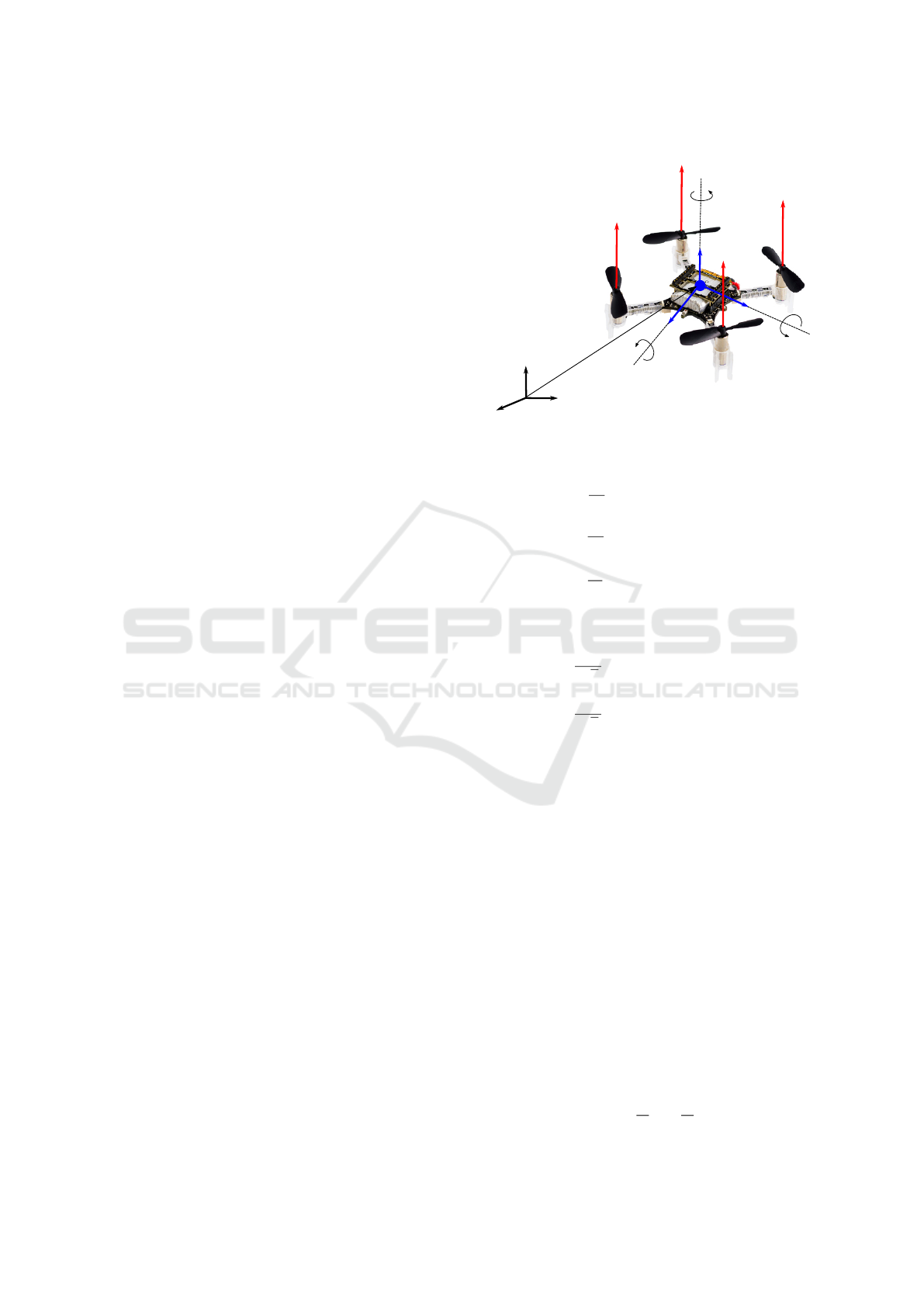
To define the dynamic model of the Crazyflie 2.X,
some hypothesis have been taken into account: the
aircraft is a rigid body with a constant mass and the
geometry and the propulsion are symmetrical. This
vehicle has six degree of freedom: the position of the
CG (Center of Gravity) of the aircraft with respect to
the inertial frame (P
CG
= {x, y, z}) and the orientation
of the quadrotor which is described by the Euler an-
gles (Φ = {φ, θ, ψ}). These angles, the roll φ, the
pitch θ and the yaw ψ represent the rotation of the
body frame with respect to the inertial frame. The po-
sition and the orientation of the drone are depicted in
Figure 1.
The state of the system can be obtained taking
into account the mechanical classical laws of motion.
The angular speeds of the body frame (p, q, r) are de-
scribed by (1)-(3),
X
B
Y
B
Z
B
P
1
P
2
P
3
P
4
X
I
Y
I
Z
I
F
I
F
B
θ
ψ
ϕ
F
1
F
2
F
3
F
4
P
CG
Figure 1: Position P
CG
= {x, y, z} and orientation Φ =
{φ, θ, ψ} of the quadrotor.
˙p =
1
I
xx
(qr (I
yy
−I
zz
) + M
x
) (1)
˙q =
1
I
yy
(rp (I
zz
−I
xx
) + M
y
) (2)
˙p =
1
I
zz
(pq(I
yy
−I
xx
) + M
z
) (3)
where M
x
, M
y
and M
z
are the momentums defined by
(4)-(6)
M
x
=
dC
T
√
2
−Ω
2
1
−Ω
2
2
+ Ω
2
3
+ Ω
2
4
(4)
M
y
=
dC
T
√
2
−Ω
2
1
+ Ω
2
2
+ Ω
2
3
−Ω
2
4
(5)
M
z
= C
D
−Ω
2
1
+ Ω
2
2
+ Ω
2
3
−Ω
2
4
(6)
where d denotes the distance from the CG to the cen-
ter of each motor, C
T
is the thrust coefficient that rep-
resents the upward force generated by each propeller
where F
i
= C
T
Ω
2
i
(Ω
i
is the angular speed of each
propeller) and C
D
the aerodynamic drag coefficient,
see Figure 1. In these equations the angular accel-
erations have been neglected because they tend to be
small compared to the other terms. On the other hand,
the gyroscopic moments have also been neglected due
to the inertia moments of the motors tends to be small
(Sabatino, 2015). The terms I
xx
, I
yy
and I
zz
denote the
inertia moments about its three axes. Based on the hy-
pothesis that the body of the quadcopter is symmetri-
cal around all its axes, all crossed terms (I
xy
, I
yz
, etc.)
can be considered equal to zero. Then, the Euler an-
gles can be obtained by the integration of the equation
(7)
˙
φ
˙
θ
˙
ψ
=
1 S
φ
T
θ
C
φ
T
θ
0 C
φ
−S
φ
0
S
φ
C
θ
C
φ
C
θ
p
q
r
(7)
ICINCO 2021 - 18th International Conference on Informatics in Control, Automation and Robotics
360

where S
i
denotes sin(i), C
i
represents cos(i) and T
i
means tan(i) with i = {φ, θ, ψ}. And, the position of
the CG of the quadrotor with respect the inertial frame
is obtained by the integration of (8)-(10)
¨x =
F
z
m
C
ψ
S
θ
C
φ
+ S
ψ
S
φ
(8)
¨y =
F
z
m
S
ψ
S
θ
S
φ
−C
ψ
S
φ
(9)
¨z =
F
z
m
C
θ
C
φ
−g (10)
where F
z
=
∑
F
i
, m is the total mass of the aircraft
and g the acceleration of gravity (9.81 m/s
2
). In (Luis
and Ny, 2016) more details of the dynamic model of
the Crazyflie 2.X are presented. Finally, in (F
¨
orster,
2015) an exhaustive work has been done to identify
the main parameters of Crazyflie 2.X.
On the other hand, linearisation is useful to design
a control system using linear classical design tech-
niques. It also allows to analyse the system character-
istics such as system stability, disturbance rejection,
and reference tracking. Considering the Crazyflie 2.X
as it was analysed in (Luis and Ny, 2016), the trim
point is F
z
= mg = 4C
T
Ω
2
e
, it means that the drone is
hovering at constant altitude. Taking into account this
assumption, the equilibrium propeller speed is
Ω
e
=
r
mg
4C
T
(11)
Once the linear model is obtained the flight modes
can be decoupled. In this case, four models can be ob-
tained: vertical, directional, lateral and longitudinal.
3 QUADROTOR’S CONTROL
SCHEME
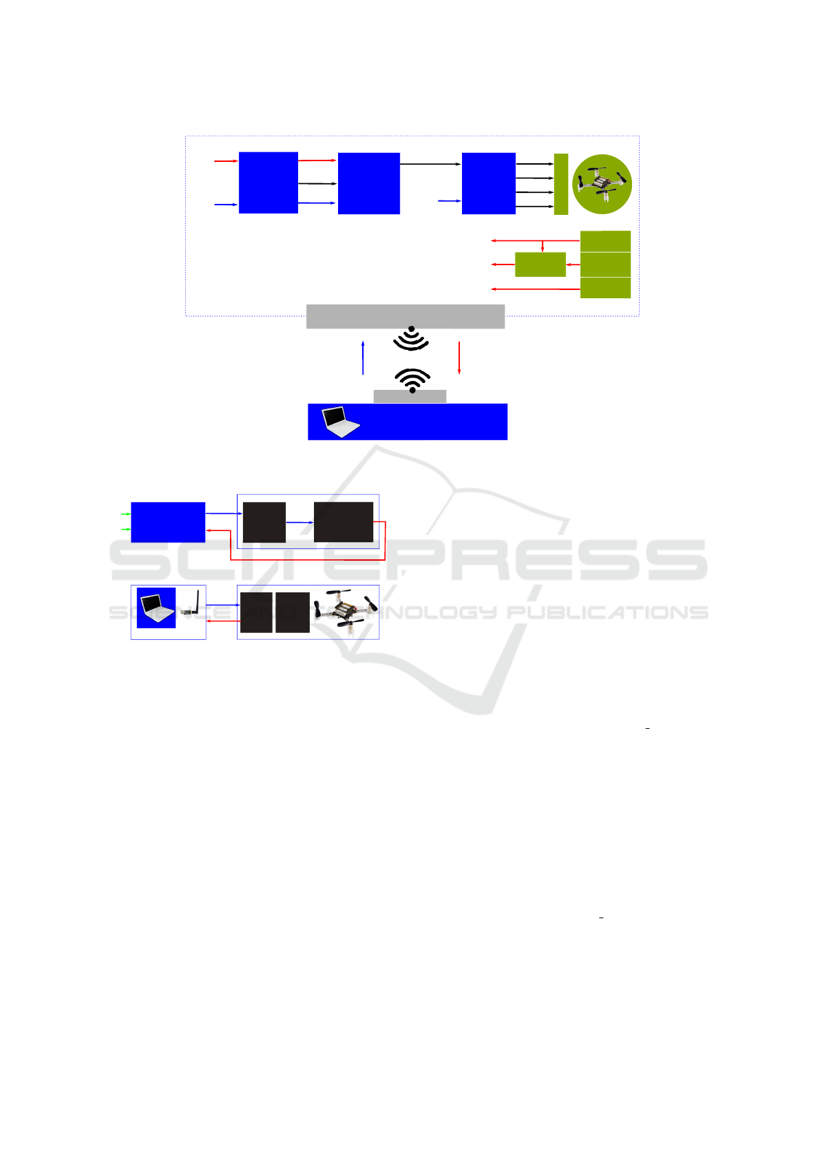
The control architecture for the Crazyflie 2.X or for
similar quadrotors is depicted in Figure 2 (Landry
et al., 2015). It is divided in two groups: the on-
board controllers inside the drone and the off-board
controllers that are implemented in external systems
such as a PC. The communication between these two
groups, the on-board and the off-board controllers, is
made by a radio interface of 2.4 GHz. There is a mo-
dem in the drone side and the crazyradio PA in the
PC side. Over this radio link, the Sensor Information
SI = (z, φ, θ, ψ, p, q, r) and the Control Commands
CC = (Ω, φ
r
, θ
r
, r
r
) are interchanged. In this archi-
tecture, the input Ω in the control mixer denotes the
thrust. This kind of robots needs high frequency con-
trol to get a stable flight. For this reason, the on-board
controllers are required. In this architecture, the rate
controller works with 500 Hz and the attitude con-
troller with 250 Hz. The set of on-board controllers
is composed by the control mixer, the rate controller
and the attitude controller, these controllers are im-
plemented in the firmware of the drone Crazyflie 2.X.
The rate controller and the attitude controller are
implemented by discrete-time PID controller (12)
u
k
= K
p
e
k
+ K
i
k
∑
n=1
e
n
+ K
d
[e
k
−e
k−1
] (12)
where u
k
is the control signal, e
k
the error signal
and K
p
, K
i
and K
d
are the controller’s gains. In the
firmware of the Crazyflie 2.X the gains for the rate
and for the attitude controllers are defined.
The Control Commands CC are used to set the
references for the on-board controllers. On the other
hand, the Sensor Information SI can be obtained with
a maximum frequency of 100 Hz. This is the main
reason why the rate and the attitude controllers can-
not be implemented outside the drone. Finally, in the
off-board controllers, the altitude, x-y position (if ad-
ditional sensors are included to get the x and y coor-
dinates) and yaw position controllers can be imple-
mented using the SI and the CC.
4 THE NEW CONTROL
ENGINEERING FRAMEWORK
The framework proposed in this work is based on
the control architecture of the Crazyflie 2.X. This
framework will help to develop quadrotor control
techniques (see Figure 3). With methodologies and
tools included in it, the researchers and students will
be able to investigate and develop new control tech-
niques applied to these types of aircrafts. This new
framework offers the necessary tools to undertake all
the stages of development, from the design of the con-
trollers to the final adjustment in the real environment.
The proposed framework is composed of two main
elements: 1) a simulation laboratory based on Mat-
lab/Simulink tools and 2) The instructions to setup
a real-world environment testing area based on the
drone Crazyflie 2.X with its hardware and software
components.
4.1 Simulation Laboratory
In the simulation laboratory (Figure 3a)) two mod-
els of the Crazyflie 2.X are available: the linear and
the non-linear model, both elements have been imple-
mented as Simulink blocks. The output is the Sensor
Information SI = (z, φ, θ, ψ, p, q, r). The input of the
A Control Engineering Framework for Quadrotors: An Application for the Crazyflie 2.X
361
(p,q,r)
CC=(Ω,ϕ
r
,θ
r
,r
r
)
SI=(z,ϕ,θ,ψ,p,q,r)
Motors
Acelerometer
Gyro
Flow deck
Loco
Sensors
Actuators
Sensor
Fusion
(ϕ,θ,ψ)
(z)
Control
Mixer
Rate
Controller
A�itude
Controller
(Δϕ,Δθ,Δψ)
(p,q,r)
(p
r
,q
r
)
(r
r
)
(Ω)
(ϕ,θ)
(ϕ
r
,θ
r
)
Input
Output
PWM
1
PWM
2
PWM
3
PWM
4
f=500Hz
f=250Hz
2.4 GHz
Off-board Controllers
Drone Crazyflie 2.X
Modem
Crazyradio PA
On-board Controllers
Figure 2: Control architecture of the Crazyflie 2.X.
SI
Crazyflie 2.X
Crazyradio PA
CC
SI
a)
b)
Model of the Crazyflie 2.X
Python - API cflib
On-board
Controllers
Linear Model
Non-Linear Model
or
Off-board
Controllers
Modem
Firmware
Actuators
Sensors
CC
PWM
(z
r
,ψ
r
)
references
z
r
ψ
r
Off-board Controllers
Figure 3: Control engineering framework. a) Simulation
laboratory in Matlab
T M
/Simulink
T M
, b) real environment
based on the Crazyflie 2.X.
model should be the moments M
x
, M
y
, M
z
and the
force F
z
, but for practical reasons, it is better to use
the motor signals PWM
i
. To use these inputs in the
models, the following relationship between the vari-
ables PWM
i
and Ω
i
is used (Luis and Ny, 2016):
Ω
i
= 0.2685PWM
i
+ 4070.3 (13)
The input of the on-board controllers is the Control
Commands CC = (Ω, φ
r
, θ
r
, r
r
). Finally, some off-
board controllers have been defined in the system,
these controllers will be described later in the prac-
tical application.
4.2 Real Environment
The real environment is composed by a PC with the
Crazyradio PA and the drone Crazyflie 2.X including
the hardware flow deck (Figure 3b). The Crazyra-
dio PA is connected to the PC and it allows the ra-
dio interface to communicate the PC with the drone.
In the PC the off-board controllers are implemented
in python scripts based on the API cflib. Using this
API a set of commands are available to interact with
the drone, some of them for getting the sensor infor-
mation (logging functionality) and others for sending
control commands to the drone. Although python is
an interpreted language, the real-time is guaranteed
because the sample rate in the radio interface is rela-
tively low.
To get the sensor information SI the logging func-
tionality of the Crazyflie 2.0 has been used. This fea-
ture allows to read the sensor information with max-
imum frequency of 100 Hz (sampling time=0.01s).
Using the API cflib, this task can be implemented in a
simple way. Using this methodology to read the sen-
sor information, the noise in these devices can be eas-
ily estimated. After calibrating the sensors, the noise
in the sensors can be modelled by a normal distribu-
tion N(µ, σ), where µ is the mean and σ the standard
deviation. In this system µ ≈ 0 and σ is presented
in Table 1. In order to get more realistic results in
the simulation laboratory, these models of the noise
will be included in the experiments. To send a control
command CC to the drone the API cflib provides the
command cf.commander.send setpoint(roll, pitch,
yawrate, thrust) where roll=φ
r
and pitch=θ
r
in de-
grees, yawrate=r
r
in degrees/s and thrust=Ω a value
between 0 and 65,535. With this command is very
easy to build many control schemes. For example,
ICINCO 2021 - 18th International Conference on Informatics in Control, Automation and Robotics
362
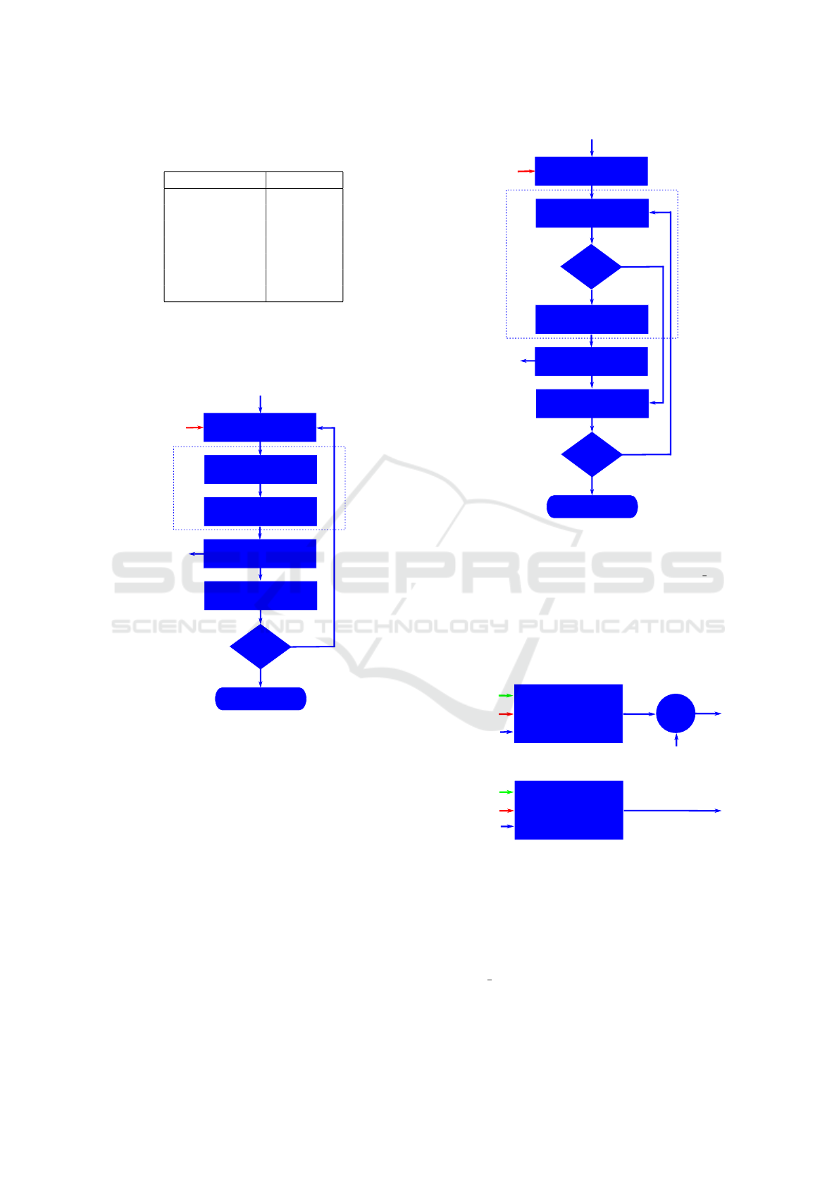
Table 1: Standard deviations (σ) for the noise model of the
sensors.
Model variable σ
z 0.00132 m
φ 0.119
o
θ 0.180
o
ψ 0.149
o
p 0.795
o
/s
q 0.752
o
/s
r 0.695
o
/s
to define a PID controller, the algorithm presented
in Figure 4 can be used. On the other hand, if an
event-based PID controller (
˚
Aarz
´
en, 1999) is needed
the structure in Figure 5 can be implemented. There
Stop
sleep(sampling_time)
Condition?
Yes
No
Exit
SI=(z,ϕ,θ,ψ,p,q,r)
TX Control Commands
RX Sensor Information
CC=(Ω,ϕ
r
,θ
r
,r
r
)
CC
SI
e=references-SI
CC=PID(e,K
p
,K
i
,K
d
)
Controller
Figure 4: Algorithm for the periodic PID. The error signal
e is obtained from the desired setpoint signals references
and the SI. In this scheme, PID() denotes a PID controller
whose parameters are the error signal e and K
p
, K
d
, K
i
which mean the proportional, integral and derivative terms.
is a wide variety of control techniques that can be used
and investigated in depth both in the simulation envi-
ronment and in the real system.
5 PRACTICAL APPLICATIONS
AND EXPERIMENTAL
RESULTS
To check the functionality and the uses cases of the
presented framework some experiments have been
proposed. To investigate the control design capabil-
Stop
sleep(sampling_time)
Condition?
Yes
No
Exit
SI=(z,ϕ,θ,ψ,p,q,r)
TX Control Commands
RX Sensor Information
CC=(Ω,ϕ
r
,θ
r
,r
r
)
CC
SI
e=references-SI
CC=PID(e,K
p
,K
i
,K
d
)
abs(e)>
Yes
No
Controller
Event_Th?
Figure 5: Algorithm for the event-based PID. This structure
has similar blocks that the PID controller but includes an
addition element called event detector (ED). The ED checks
if the error signal e crosses the event threshold Event Th.
ities of the framework, in this experiment, two au-
topilots have been developed in the off-board con-
trollers. The first autopilot AP1 is an altitude (z) con-
troller and the second one AP2 is a directional (ψ)
controller (see Figure 6). These autopilots have been
a)
b)
PID
Periodic & Event
z
r
ψ
r
+
z
Event_Th
PID
Periodic & Event
Event_Th
ψ
Ω
e
Ω
c
Ω
r
r
Figure 6: The proposed autopilots. a) AP1: altitude con-
troller, b) AP2: directional controller.
developed by classical periodic PID controllers and
by event-based PID controllers. In this way, these
two control schemes can be compared. These con-
trollers can work in both modes: periodic PID or
event-based PID. On the one hand, when the parame-
ter Event T h=0, the system works in a periodic mode.
On the other hand, when this parameter is higher than
zero it works as an event-based controller. The ob-
A Control Engineering Framework for Quadrotors: An Application for the Crazyflie 2.X
363

jective of the altitude controller (Figure 6 a)) is the
tracking of the reference signal z
r
. The output Ω that
is set to the on-board controller, it is composed of the
output of the PID, Ω
c
, and the equilibrium signal Ω
e
.
The directional controller (Figure 6 b)) uses the refer-
ence signal ψ
r
and the sensor information ψ to calcu-
late the reference signal r
r
for the on-board controller.
In this application, the reference signals φ
r
and θ
r
are
set to zero because these autopilots allow the hovering
of the drone.
To design these controllers, the Matlab Control
System Toolbox has been used. With these tools,
the controller’s gains have been obtained, at the same
time, to check the event-based implementation the
thresholds Event T h has been set. In (Socas et al.,
2015) some methodologies to set event-based con-
trollers have been presented, using these methods the
event-based controller can be set in a simple way. In
Table 2 the parameters of the designed off-board con-
trollers are shown.
Table 2: Parameters of the off-board controllers.
Parameter Altitude Directional
K
p
9,500 40
K
i
0 10
K
d
45,000 25
Event T h 0.008 m 5
o
In the simulation laboratory the linear and the non-
linear model of the Crazyflie 2.X have been analysed
considering the previous controllers. Once it has been
checked that the results of both models are similar,
only the non-linear model of the drone has been con-
sidered in this work because it is the most realistic
one. The experiments last 15s and the two reference
signals have been modified. The altitude reference z
r
is set to 0.4 m at t = 0s and at t = 5s the yaw ref-
erence ψ
r
has a slope of 15
o
/s until it reaches 90
o
at
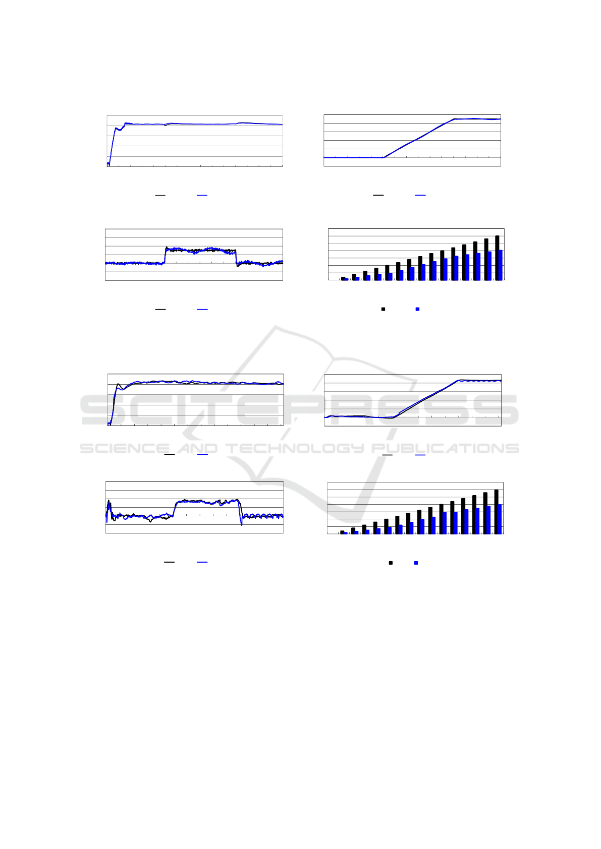
t = 11s. In these experiments, the models of noise
presented in Table 1 are also included. The simu-
lation results are depicted in Figure 7. In these fig-
ures the results for the periodic controller and for the
event-based controller are presented. The designed
controllers have similar behaviour and present a good
tracking of the reference signals, according to Figure
7 a) and b). The main difference between the periodic
and the event-based schemes is the activity of the con-
trollers. In these experiments, the periodic controllers
take around 3,000 control actions but the event-based
implementation only needs 67% of the control actions
than the periodic system (see Figure 7 d)).
In view of these simulation results, the Crazyflie
2.X can be operated safely in the real environment.
Once satisfactory results have been achieved in the
simulation setup, the next step is to check the be-
haviour of these controllers in the real environment.
The results obtained in these experiments are shown
in the Figure 8. In this case, both controllers have
a stable response and present a good tracking of the
reference signals (see Figure 8 a) and b)). In the real
environment the controllers have to compensate the
disturbances that occur during takeoff, the turbulence
produced by the drone in the air and the noise in the
sensors. These effects are clearly observed in the vari-
able r in Figure 8 c), and also to a lesser extent in
the variables z and ψ (see Figure 8). In the simula-
tion models, only the noise of the sensors has been
considered. This is a good approach because the real
event-based solution and the simulation model gener-
ate the same number of events (see Figure 7 d) and
Figure 8 d)).
To evaluate the performance of these controllers
and also to compare the event-based controllers with
respect to periodic classical approaches, the perfor-
mances indexes introduced in (S
´
anchez et al., 2009)
can be used. In this work, the IAE Integral Absolute
Error and the N
N
ratio of events have been consid-
ered. Taking into account the results of the experi-
ments, the performance indexes for these controllers
are presented in Table 3.
Table 3: Performance indexes for the altitude and direc-
tional controllers.
Altitude Controller IAE(m) N
N
(%)
Periodic PID 38.34 100
Event PID 39.52 73
Directional Controller IAE(
o
/100) N
N
(%)
Periodic PID 28.44 100
Event PID 36.80 59
In these experiments, if the periodic PID con-
troller is considered as the reference, the event-based
altitude controller presents better results than the
event-based directional controller. In this case, the
IAE is 39.52 vs. 38.34 for the altitude (3% higher) and
36.80 vs. 28.44 (29% higher). Moreover, regarding
the ratio of events N
N
the altitude controller reaches a
value of 73% while the directional controller obtains
59%. Thus the directional controller shows better re-
sults than the altitude controller. The results illustrate
that the accuracy of the altitude controller is better
than the directional controller. However if the activity
is taken into account, the directional controller has a
better behaviour than the altitude controller (59% vs.
73% respectively).
ICINCO 2021 - 18th International Conference on Informatics in Control, Automation and Robotics
364
-20
0
20
40
60
80
100
0 1 2 3 4 5 6 7 8 9 10 11 12 13 14 15
t(s)
ψ(˚)
Periodic NL Event NL
-20
-10
0
10
20
30
40
0 1 2 3 4 5 6 7 8 9 10 11 12 13 14 15
t(s)
r(˚/s)
Periodic NL Event NL
0
500
1,000
1,500
2,000
2,500
3,000
3,500
0 1 2 3 4 5 6 7 8 9 10 11 12 13 14 15
t(s)
Accumulated samples vs. events
Periodic NL Event NL
b)
c)
d)
0,00
0,10
0,20
0,30
0,40
0,50
0 1 2 3 4 5 6 7 8 9 10 11 12 13 14 15
t(s)
z(m)
Periodic NL Event NL
a)
Figure 7: Simulation results for the non-linear model. Black line represents the response for the periodic controller and blue
line for the event-based implementation. a) Altitude z, b) yaw ψ, c) yaw rate r and d) accumulated samples vs. accumulated
events.
0.00
0.10
0.20
0.30
0.40
0.50
0 1 2 3 4 5 7 8 9 10 11 12 14 15
t(s)
z(m)
Periodic Event
-20
0
20
40
60
80
100
0 1 2 3 4 5 7 8 9 10 11 12 14 15
t(s)
ψ(˚)
Periodic Event
a)
b)
0
500
1,000
1,500
2,000
2,500
3,000
3,500
0 1 2 3 4 5 6 7 8 9 10 11 12 13 14 15
t(s)
Accumulated samples vs. events
Periodic Event
-20
-10
0
10
20
30
40
0 1 2 3 4 5 7 8 9 10 11 12 14 15
t(s)
r(˚/s)
Periodic Event
c)
d)
Figure 8: Experimental results. a) Altitude z, b) yaw ψ, c) yaw rate r and d) accumulated samples vs. accumulated events.
Black line represents the response for the periodic controller and blue line for the event-based implementation.
6 CONCLUSIONS
A new framework for quadrotor control engineering
has been proposed. The two main elements, the simu-
lation laboratory and the real environment offer to en-
gineers and researchers all the tools needed to develop
control applications on drone platforms. In this work,
the solution has been particularized for the Crazyflie
2.X, but it can be applied to other quadrotors in a sim-
ple way. All elements in the framework have been
described in detail and the guidelines to develop con-
trol applications for the Crazyflie 2.X have been ex-
plained in depth. A practical application to test this
new proposal has been investigated. In this case, two
autopilots have been designed and analysed in this
framework using periodic PID and event-based PID.
The simulation and experimental results show that it
is very simple to design these controllers using this
A Control Engineering Framework for Quadrotors: An Application for the Crazyflie 2.X
365

approach. Finally, some performance indexes have
been introduced to validate the response of the de-
signed controllers.
ACKNOWLEDGEMENTS
This work was supported in part by the Spanish
Ministry of Economy and Competitiveness under
the Project CICYT RTI2018-094665-B-I00 and the
Project CICYT DPI2017-84259-C2-2-R. Also, the
Project GID2016-6 supported by UNED.
REFERENCES
˚
Aarz
´
en, K.-E. (1999). A simple event-based pid controller.
IFAC Proceedings Volumes, 32(2):8687–8692.
Andrievsky, B., Fradkov, A., and Peaucelle, D. (2005).
Adaptive control experiments for laas” helicopter”
benchmark. In 2005 International Conference on
Physics and Control, PhysCon 2005, pages 760–765.
Emran, B. J. and Najjaran, H. (2017). Adaptive neural net-
work control of quadrotor system under the presence
of actuator constraints. In 2017 IEEE International
Conference on Systems, Man, and Cybernetics (SMC),
pages 2619–2624. IEEE.
Fan, Y., Cao, Y., and Li, T. (2017). Adaptive integral back-
stepping control for trajectory tracking of a quadro-
tor. In 2017 4th International Conference on Informa-
tion, Cybernetics and Computational Social Systems
(ICCSS), pages 619–624. IEEE.
F
¨
orster, J. (2015). System identification of the crazyflie 2.0
nano quadrocopter. B.S. thesis, ETH Zurich.
Giernacki, W., Skwierczy
´
nski, M., Witwicki, W., Wro
´
nski,
P., and Kozierski, P. (2017). Crazyflie 2.0 quadrotor as
a platform for research and education in robotics and
control engineering. In 2017 22nd International Con-
ference on Methods and Models in Automation and
Robotics (MMAR), pages 37–42. IEEE.
Landry, B. et al. (2015). Planning and control for quadro-
tor flight through cluttered environments. PhD thesis,
Massachusetts Institute of Technology.
Lee, B.-Y., Lee, H.-I., and Tahk, M.-J. (2013). Analysis of
adaptive control using on-line neural networks for a
quadrotor uav. In 2013 13th International Conference
on Control, Automation and Systems (ICCAS 2013),
pages 1840–1844. IEEE.
Luis, C. and Ny, J. L. (2016). Design of a trajectory track-
ing controller for a nanoquadcopter. arXiv preprint
arXiv:1608.05786.
Mahony, R., Kumar, V., and Corke, P. (2012). Multirotor
aerial vehicles: Modeling, estimation, and control of
quadrotor. IEEE Robotics and Automation magazine,
19(3):20–32.
Sabatino, F. (2015). Quadrotor control: modeling, nonlin-
ear control design, and simulation. Ms thesis, KTH
Royal Institute of Technology, Stockholm, Sweden.
Safaei, A. and Mahyuddin, M. N. (2016). Lyapunov-based
nonlinear controller for quadrotor position and atti-
tude tracking with ga optimization. In 2016 IEEE
Industrial Electronics and Applications Conference
(IEACon), pages 342–347. IEEE.
S
´
anchez, J., Guarnes, M., Dormido, S., and Visioli, A.
(2009). Comparative study of event-based control
strategies: An experimental approach on a simple
tank. In 2009 European Control Conference (ECC),
pages 1973–1978. IEEE.
Shirai, J., Yamaguchi, T., and Takaba, K. (2017). Remote
visual servo tracking control of drone taking account
of time delays. In 2017 56th Annual Conference of the
Society of Instrument and Control Engineers of Japan
(SICE), pages 1589–1594. IEEE.
Socas, R., Dormido, S., and Dormido, R. (2015). Event-
based control strategy for the guidance of the
aerosonde uav. In 2015 European Conference on Mo-
bile Robots (ECMR), pages 1–6. IEEE.
Taniguchi, T., Eciolaza, L., and Sugeno, M. (2014).
Quadrotor control using dynamic feedback lineariza-
tion based on piecewise bilinear models. In 2014
IEEE Symposium on Computational Intelligence in
Control and Automation (CICA), pages 1–7. IEEE.
Wahyunggoro, O., Cahyadi, A. I., et al. (2016). Trajec-
tory and altitude controls for autonomous hover of a
quadrotor based on fuzzy algorithm. In 2016 8th Inter-
national Conference on Information Technology and
Electrical Engineering (ICITEE), pages 1–6. IEEE.
Zhang, K., Chen, J., Chang, Y., and Shi, Y. (2016). Ekf-
based lqr tracking control of a quadrotor helicopter
subject to uncertainties. In IECON 2016-42nd Annual
Conference of the IEEE Industrial Electronics Society,
pages 5426–5431. IEEE.
Zhou, J., Deng, R., Shi, Z., and Zhong, Y. (2017). Robust
cascade pid attitude control of quadrotor helicopters
subject to wind disturbance. In 2017 36th Chinese
Control Conference (CCC), pages 6558–6563. IEEE.
ICINCO 2021 - 18th International Conference on Informatics in Control, Automation and Robotics
366
