
On the Design and Fabrication of a Voice-controlled Mobile Robot
Platform
Saleh Ahmad, Mohammed Khalid Alhammadi, Abdulla Adel Alamoodi, Ahmed Nasser Alnuaimi,
Saif Aref Alawadhi and Abdulla Ahmed Alsumaiti
Mechatronics Engineering Technology, Higher Colleges of Technology, D54, Academic City, Dubai, U.A.E.
Keywords: Voice Control, Service Robots, AI JARVIS.
Abstract: The ‘voice’ is the most popular form of communication for human beings is. In the field of service robots, the
application of speech recognition is a natural choice. Service robots minimize the physical work that people
render with their day-to-day tasks. The development of a mobile robot platform that can be controlled using
speech commands is presented in this paper. The human voice commands are recognized by the AI JARVIS
voice recognition software and translated into motion commands sent to the mobile robot platform using RF
communication. Not only does the mobile robot recognize the voice commands and execute them, but it also
provides acknowledgment by voice output. The designed mobile robot can carry out various movements,
turns, and shifting objects from one location to another. The voice commands are processed using the modified
AI JARVIS voice recognition software. Using an RF module's wireless end-point networking, voice signal
commands are directly transmitted to the Robot. The mobile robot is developed on a Microcontroller based
platform. Performance evaluation showed promising results from the initial experiments. Possible
improvements in the future deployment of such a robot in households, hospitals, and other sectors are also
explored.
1 INTRODUCTION
The most common means of communication in
humans is through voice. About every
communication is held using voice signals to
communicate. Using a microphone, sounds, and
speech signals can be translated into electrical
signals. Voice recognition is a technique used to
translate voice signals into a text format for a device
or instructions for a computer. It is possible to use this
voice recognition system to control and generate
speech acknowledgment. Voice-controlled robots
understand and execute the necessary acts with
thousands of voice commands.
Voice recognition is a challenging task since each
person has a unique speech pattern. However,
significant progress has been made due to the recent
developments in Artificial Intelligence (AI)
algorithms. Voice controller mobile robots can be
used in various sectors such as manufacturing,
defense, medical care, etc. In hospitals, these robots
can be used to deliver medicines or medical
equipment, sanitize/disinfect rooms, patrol corridors,
and provide voice instructions (Ozkil et al, 2009) and
(Mettler et al, 2017).
Several virtual speech assistants, such as Google
Assistant and Amazon Alexa, are available to allow
users to interact comfortably with smart devices with
only their voice. However, these speech assistants are
difficult to customize to suit the needs of this work.
There are several research publications in the area of
voice control of robots (Chaudhry et al 2019 - Uehara
et al, 2010).
In (AbhinavSalim et al, 2017), the presented work
explains the use of voice control to control a robotic
arm. The voice commands are first trained using the
speech recognition module by the operator. The
commands are stored as numbers with a range
between 1 and 9. If the operator says one of the
predefined commands near the microphone of the
speech recognition module, the command will be
recognized and the corresponding Binary Coded
Decimal (BCD) of the number is sent as an output.
According to the BCD command received by the
microcontroller, appropriate signals are now sent to
the motor driver to rotate the motors in the desired
direction.
Ahmad, S., Alhammadi, M., Alamoodi, A., Alnuaimi, A., Alawadhi, S. and Alsumaiti, A.
On the Design and Fabrication of a Voice-controlled Mobile Robot Platform.
DOI: 10.5220/0010465701010106
In Proceedings of the 18th International Conference on Informatics in Control, Automation and Robotics (ICINCO 2021), pages 101-106
ISBN: 978-989-758-522-7
Copyright
c
2021 by SCITEPRESS – Science and Technology Publications, Lda. All rights reserved
101
The design of a smart, motorized, voice-
controlled wheelchair using an embedded system is
described in (Ali, 2015). To assist the navigation of
the wheelchair, the Arduino microcontroller and
speaker-dependent voice recognition processor were
used. The wheelchair’s direction and velocity are
controlled by pre-defined Arabic voice commands.
This paper suggests the use of a virtual speech
assistant named AI JARVIS that combines the ease of
use and the operational complexity of the other visual
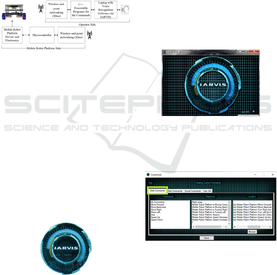
assistant’s platforms. Figure 1 depicts a block
diagram of the voice-controlled mobile robot system.
Figure 1: Block diagram of the voice-controlled mobile
robot platform.
2 ADAPTATION OF THE AI
JARVIS VIRTUAL CONTROL
ASSISTANT TO CONTROL THE
MOBILE ROBOT PLATFORM
2.1 Robot Platform
AI JARVIS is a virtual assistant designed to give
voice commands to personal computers (PCs). The
AI JARVIS wizard has the following functions:
Gmail email reader, Facebook notification reader;
Facebook messaging reader; integrated alarm;
reminders; browser control (Chrome and Firefox);
Windows player control; control Windows; Editor to
open any folder, any application, web page; Editor to
add questions and answers to the wizard; Wikipedia
search; and Google YouTube search. The AI JARVIS
voice assistant software icon is shown in Figure 2.
Figure 2: J.A.R.V.I.S-Just A Rather Very Intelligent
System.
The adaptation of the JARVIS virtual control
assistant was done by creating programs in visual C#,
which allows different types of codes to be sent to the
Microcontroller depending on the voice instruction
given to the JARVIS virtual assistant. Once the code
reaches the Microcontroller, it performs a
programming logic that allows activating and
deactivating the mobile robot motors and selects their
angular velocities which in turn will allow control of
the mobile robot movements. The voice commands
are given to the AI JARVIS virtual control assistant
utilizing a wireless headset microphone.
The steps needed for utilizing the AI JARVIS to
control the mobile robot platform by voice are
described in this section. The features of the Al
JARVIS software will be explained first. After the AI
JARVIS software is started, the window shown in
Figure 3 will appear. The next step is to configure the
required custom commands.
Figure 3: JARVIS software startup window.
To configure new commands, one needs to click
on the plus button on the bottom of the right-hand side
of the AI JARVIS software as shown in Figure 3.
After clicking on the plus button, the popup window
shown in Figure 4 will appear.
Figure 4: Creating a custom shell command.
There are three types of commands available in
JARVIS
1. Shell commands
2. Web commands
3. Social commands
ICINCO 2021 - 18th International Conference on Informatics in Control, Automation and Robotics
102
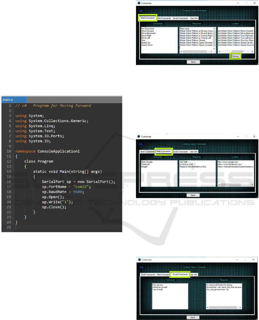
2.1.1 Shell Commands
The shell commands are the most important feature
for this work. It allows users to create commands that
result in the execution of a custom-made standalone
executable C# console application. These C#
executable files have been designed to send certain
instructions over the RF communication modules
based on the user voice commands. These
instructions are interpreted by the Microcontroller.
Based on the received instruction, the Microcontroller
communications with the motor drive to execute the
desired movement/action. A sample of the C# script
is shown in Figure 5.
Figure 5: C# script for the move forward shell command.
There are three columns inside the shell command
window as shown in Figure 6. The commands in the
first column are (what is the command, what the
operator is going to say). There is a response next to
the command (what is the corresponding response to
your command) and then the location (browse for the
file or application which is going to be opened by
JARVIS based on the command).
First, the command is typed, and then the response
that we need and then click on the browse button to
choose the application. The application in our case is
the executable file of the C# console application that
was written to send the desired command to the
Microcontroller.
Figure 6: Chosen application for custom commands.
2.1.2 Web Commands
To access such commands, click on the web
commands on the top toolbar as shown in Figure 7.
Then enter the custom command and the response in
the web commands window similar to shell
commands and give the URL for the web page that
needs to be opened.
Figure 7: Creating custom web commands.
2.1.3 Social Commands
Social commands, which have two columns, one is
the command and the other is the response, are used
to interact with AI JARVIS. Figure 8 illustrates how
to create a custom social command.
Figure 8: Creating custom social command.
On the Design and Fabrication of a Voice-controlled Mobile Robot Platform
103

3 MOBILE ROBOT DESIGN
3.1 Motor Sizing Calculations
To ensure the efficiency, durability, and cost of the
designed mobile robot platform, proper sizing, and
selection of the mobile robot platform motors is of
paramount importance. This section describes the
steps taken to achieve this task.
Step 1: Calculate the required wheel torque and
rotational speed (RPM).
Step 2: Research DC motor manufacturers to
determine the availability of gear-head motors that
meet the functional requirements and the design
parameters. The list of the desired design parameters
for the mobile robot platform is given in Table 1.
Table 1: Mobile robot platform design parameters.
Design Parameter Value
Mass 15 kg (including payload)
Wheel Diameter 0.1 m
Desired Speed 1.3 m/s
Desired Acceleration 0.9 m/s2
To calculate the required motor torque, we will
start with Newton's second law, as follows
𝐹 = 𝑚𝑎
(1)
Where 𝐹 denotes the total force that needs to be
exerted by the mobile robot (N), 𝑚 denotes the total
mass of the robot and its maximum payload (Kg), 𝑎
denotes the linear acceleration (m/s
2
).
Substituting the values of 𝑚 and 𝑎 from Table 1.
𝐹 = 15 ∗ 0.9 = 13.5 𝑁 (2)
This force needs to be translated into motor
torques, 𝜏
using the following equations:
𝜏
= 𝐹∗ 𝑊
(3)
Where 𝑊
represents the wheel radius,
𝑊
= 0.1/2 = 0.05 m.
Since we have two actuated wheels, the force
required per wheel is, 𝐹 = 6.75 𝑁.
Substituting the values of 𝐹 and 𝑊
into
Equation (3), we obtain
𝜏
= 6.75 ∗ 0.05 = 0.3375 Nm
(4)
The following equations describe how to calculate
the required wheel rotational speed (RPM) to
maintain a mobile robot platform speed of 1.3 m/s.
We need first to calculate the wheel
circumference as follows,
𝑊
= 𝜋 𝑥 𝑊
≅ 3.142 ∗ 0.1 = 0.3142 𝑚.
(5)
The desired mobile robot platform speed, 𝑣 =
1.3 𝑚/𝑠.
Equation 6 describes the relationship between the
mobile robot's linear velocity and the angular speed
(Rotation per Second) and wheel circumference.
𝒗= 𝑅𝑃𝑆∗𝑊
(6)
Where 𝑅𝑃𝑆 denotes the speed in rotation per second
and 𝑊
is the wheel circumference.
Substituting the values of 𝑣 and and 𝑊
into
Equation (6), we obtain
𝑅𝑃𝑆 =
𝑣
𝑤𝑐
⁄
=
1.3
0.3142
= 4.137
(7)
Since RPS = RPM/60
𝑅𝑃𝑀 = 𝑅𝑃𝑆 ∗ 60 = 248.25
(8)
Having the designed value for the torque and the
RPM, the next step is to research DC motor
manufacturers for a suitable gearhead. The following
DC motor Gm25-370ca was selected based on the
obtained motor torque and RPM.
3.2 Microcontroller and Motor Drive
The Arduino Uno is an atmega328-based
Microcomputer. It includes 14 general-purpose
digital input/output pins. 6 pins out of the 14 GP I/O
pins support pulse width modulation (PWM). This
Microcomputer also has 6 analog pins, 16 MHz
ceramic resonator, and it includes all the required
peripherals within a single board. The mobile robot
platform uses the Arduino Uno Microcontroller as the
main central processing unit. The power supply to the
motors, the Arduino board, and all other electronics
is provided by a 12 V rechargeable lithium battery.
ZigBee modules are interfaced with the
microcontroller and the personal computer (operator
side) to establish wireless end-point networking.
The Dual-Channel DC Motor Driver-12A has
been used to drive the mobile robot platform wheels.
It is a dual-channel DC motor driver with an
extremely small size of 1.97”×1.97”×0.49”. The
module comes with two motor channels that can drive
two motors simultaneously, and each channel
employs an indicator to show the rotation direction of
the motor: blue is forward rotation, red is reverse
rotation. Support motor voltage ranges from 6.5V to
37V. Each motor channel can output 12A current
continuously and the max power of the DC motor the
module supports is up to 290W. The momentary peak
current can reach up to 70A and last about 100ms. At
the same time, the highly timing optimization of the
units inside the driver makes the minimum pulse
width of PWM input as narrow as 2us, which fully
ensured its dynamic adjustment range and greatly
ICINCO 2021 - 18th International Conference on Informatics in Control, Automation and Robotics
104
improved the quality of controlling motors
(DFRobot, 2020, December 09).
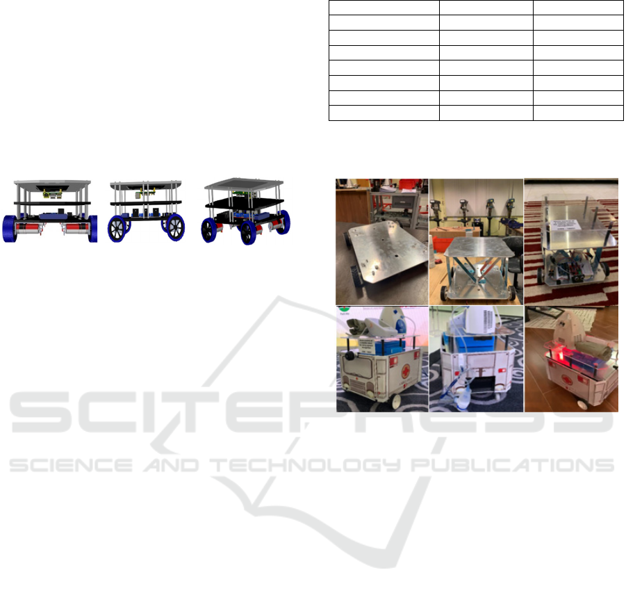
3.3 Mechanical Design
The mobile robot platform chassis, motor mounting
brackets, the brackets for holding the electronics,
sensors, and the IP camera were designed using
SolidWorks software. The chassis and the motor
brackets were made of 5 mm thick aluminum plates.
Figure 9 shows different views of the designed
mobile robot platform.
Figure 9: Different views of the mobile robot platform
assembly.
3.4 Algorithm
- The AI JARVIS software should be trained to
recognize the custom-made voice commands.
- Then the stored voice commands are represented
by binary values. For example, Move Forward is
represented by 0001, and Move Backward is
represented by 0010, etc.
- These binary values are transmitted via a ZigBee
module which is at the operator side. This is
achieved by executing the executable file of a C#
console application for that particular command.
- The transmitted binary values are then received by
another ZigBee module which is the mobile robot
platform side.
- The Microcontroller interoperates the received
binary value and performs the required action
(control the DC motors) according to that binary
value.
4 EXPERIMENTAL RESULTS
After configuring the required shell commands of the
AI JARVIS software to execute the custom
standalone executable file of the C# console
application. The Arduino code responsible for the
command parsing and controlling the robot motors
with the motor drive was completed. The AI JARVIS
software was tested to evaluate the success rate of the
saved commands. The results of this test are
summarized in Table 2.
Table 2: Voice commends performance results.
Voice Command Re
p
etition Success Rate
Move Forwar
d
100 94%
Move Backwar
d
100 95%
Turn Right 100 91%
Turn Left 100 89%
Stop 100 98%
S
p
eed UP 100 87%
S
p
eed Down 100 88%
Figure 10 shows screenshots of the developed
voice-controlled mobile robot platform.
Figure 10: Screenshots of the developed voice-controlled
mobile robot platform.
5 CONCLUSIONS
The proposed prototype of a voice-controlled mobile
robot platform has been developed and proven
effective in fulfilling user commands efficiently. For
teleoperated mobile robot applications, operators
who, for some reason, are unable or unwilling to use
a joystick controller or a keyboard to operate a mobile
robotic system can now use their voices as an
alternative. Even though the potentials for future
further research and development are still wide open,
the current version of the voice-controlled mobile
robot platform has already been demonstrated to be
useful, easy to use, and flexible. Future research could
be directed towards the use of a trained RRN network
for voice recognition instead of using the JARVIS
software.
On the Design and Fabrication of a Voice-controlled Mobile Robot Platform
105

REFERENCES
Ozkil, Al & Fan, Zhun & Dawids, Steen & Aanæs, Henrik
& Kristensen, Jens & Christensen, Kim. (2009). Service
Robots for Hospitals: A Case Study of Transportation
Tasks in a Hospital. 289 - 294.
10.1109/ICAL.2009.5262912.
Mettler, T., Sprenger, M., & Winter, R. (2017). Service
robots in hospitals: New perspectives on niche
evolution and technology affordances. European
Journal of Information Systems, 26(5), 451–468.
https://doi.org/10.1057/s41303-017-0046-1.
A. Chaudhry, M. Batra, P. Gupta, S. Lamba and S. Gupta,
"Arduino Based Voice Controlled Robot," 2019
International Conference on Computing,
Communication, and Intelligent Systems (ICCCIS),
Greater Noida, India, 2019, pp. 415-417, doi:
10.1109/ICCCIS48478.2019.8974532.
S. Patil, A. Abhigna, Arpitha, Deepthi and Priyanka, "Voice
Controlled Robot Using Labview," 2018 International
Conference on Design Innovations for 3Cs Compute
Communicate Control (ICDI3C), Bangalore, 2018, pp.
80-83, doi: 10.1109/ICDI3C.2018.00025.
Chikhale, Mr V., et al. "Voice Controlled Robotic System
using Arduino Microcontroller." International Journal
of New Technology and Research, vol. 3, no. 4, Apr.
2017.
S.R.Nair, S.R.Nair, “Design of a Voice Controlled Robotic
Arm for Picking and Placing an Object”, IOSR Journal
of Engineering, Vol 2(4), pp 670-673, April 2012.
R.Aswinbalaji, A.Arunraja “Wireless Voice Controlled
Robotics Arm”, ISSN: pp 0976-1353 Vol. 12(4), 2015.
A. Dey, A. Pal, S. Nandi, L. Roy, “Three Way Controlled
Android Smartphone based Robotic Vehicle via
Bluetooth”, International Journal of Advanced
Research in Computer and Communication
Engineering, Vol. 4(9), 2015.
P. M. Reddy, S. P. Kalyan Reddy, G. R. Sai Karthik and B.
K. Priya, "Intuitive Voice Controlled Robot for
Obstacle, Smoke and Fire Detection for Physically
Challenged People," 2020 4th International Conference
on Trends in Electronics and Informatics
(ICOEI)(48184), Tirunelveli, India, 2020, pp. 763-767,
doi: 10.1109/ICOEI48184.2020.9143048.
H.Uehara, H. Higaand, T.Soken, “A Mobile Robotic Arm
for people with severe disabilities”, International
Conference on Biomedical Robotics and
Biomechatronics (BioRob), 3rd IEEE RAS and EMBS,
Tokyo, pp. 126- 129, September 2010, ISSN:2155-
1774.
AbhinavSalim, Ananthraj C R, Prajin Salprakash, Babu
Thomas, “Voice Controlled Robotic Arm”,
International Research Journal of Engineering and
Technology, Vol.4, Issue 4, P. 2121-2124, April 2017.
Ali A. Abed, “Design of Voice Controlled Smart
Wheelchair”, International Journal of Computer
Applications, Vol.131, Issue 1, P.32-38, December
2015.
DFRobot, Dual-Channel DC Motor Driver-12A. (n.d.).
Retrieved December 09, 2020, from
https://www.dfrobot.com/product-1861.html
ICINCO 2021 - 18th International Conference on Informatics in Control, Automation and Robotics
106
