
Approach for Evolving Sensing and Actuation Devices in Cyberphysical
Systems Architectures
Diego C. Sales
1,2
and Leandro B. Becker
1
1
Graduate Program on Automation and Systems Engineering (PPGEAS), Federal University of Santa Catarina - UFSC,
Florianópolis, SC, Brazil
2
Federal Institute of Amazon - IFAM, Campus Manaus Distrito Industrial, AM, Brazil
Keywords:
Evolution Approach, Systems Architecture, Sensors, Actuators, Quality Attributes.
Abstract:
The constant technological evolution, in this case targeting sensing and actuation devices (S&A), causes de-
signers to evaluate potential modifications (upgrades) in the architecture of cyberphysical systems (CPS).
Including or exchanging S&A devices in the architecture is a complex activity that requires the use of a sys-
tematic approach. This paper presents the CPS Architectural Evolution Approach (CAvA), which provide
means to evaluate the impacts on architecture components, requirements, and software quality characteristics
for mitigating risks and possible failures on meeting design goals. CAvA proposes a set of phases and activities
to guide designers in the selection, evaluation, integration, and compatibility through the analysis of software
quality attributes, based on the ISO/IEC 25010. A software tool was designed to support CAvA application. A
case study is presented to highlight CAvA benefits for evolving the architecture of a small-scale UAV, showing
a set of possible scenarios according to predefined goals.
1 INTRODUCTION
In recent years, different approaches have been pro-
posed to guide designers in the challenge of architec-
tural evolution. Exchanging architecture components
to meet new design requirements demands the use of a
systematic approach capable of encompassing a set of
phases to ensure that changes do not generate risks to
other subsystems and components (Bass et al., 2013).
S&A devices are important components in the ar-
chitecture of CPS applications due their ability to
provide information/data from the environment/plant
(physical) to the (cyber) software that performs the
control by sending electrical signals to actuators (Lee
and Seshia, 2016). Due technological evolution,
commercial-off-the-shelf (COTS) devices have ex-
panded their application range by using new con-
version phenomena (electromechanical, electrochem-
ical), improved technical specifications (accuracy, re-
sponse time), hardware interfaces, and more recently
by combining multiple functionalities in a single de-
vice.
The architecture evolution by exchanging S&A
devices, enables the improvement of software qual-
ity characteristics such as performance, reliability,
safety, new adjustments, functionalities and require-
ments to extend the system life cycle and the com-
pliance with new requirements. However, selecting
potential candidates, defining, evaluating, defined cri-
teria, and modification analysis for architecture com-
patibility is not a trivial task, due to interface particu-
larities, device types, characteristics and distinct tech-
nical specifications that are defined by each manufac-
turer (Mohamed et al., 2007). The exchange of one
or more devices may include modifications to the sys-
tem architecture and design, such as: data type, access
address, addition of new devices to provide the ap-
propriate interface, provision of compatible protocols,
redistribution of available resources, and new deploy-
ment parameters.
The use of an approach that supports the evalua-
tion and analysis in the exchange of these devices is
of great value to designers because it allows identify-
ing risks and impacts on architecture. The literature
presents different methods and approaches of sys-
tem design that include architecture tradeoff analysis,
evaluation and COTS selection (Barbacci et al., 1998;
Bass et al., 2013). These approaches are composed of
a set of phases and activities that guide the team of de-
signers during the development of the systems. How-
ever, gaps in these approaches are observed, such as:
selection and evaluation of multiple COTS; architec-
306
Sales, D. and Becker, L.
Approach for Evolving Sensing and Actuation Devices in Cyberphysical Systems Architectures.
DOI: 10.5220/0010310303060313
In Proceedings of the 9th International Conference on Model-Driven Engineering and Software Development (MODELSWARD 2021), pages 306-313
ISBN: 978-989-758-487-9
Copyright
c
2021 by SCITEPRESS – Science and Technology Publications, Lda. All rights reserved

ture space exploration based on COTS; impact anal-
ysis of the architecture caused by COTS tradeoff; ar-
chitecture evaluation tool with support for modeling.
Thus, this paper aims to present an alternative solu-
tion, named CAvA, to addresses the observed gaps.
The CAvA approach consists in a set of phases
and related activities that guide designers in the explo-
ration of scenarios, evaluation and analysis of archi-
tecture requirements and quality attributes impacted
by the change of one or more S&A devices, based
on the ISO/IEC 25010(ISO/IEC, 2011). The proposal
uses Model-Driven Engineering (MDE) concepts for
enabling the exploration of multiple solutions, pro-
viding tool support, and guiding designers in step-
by-step activities. As part of the process, the Ar-
chitecture analysis & Design Language (AADL) and
the Requirement Specification Language (ReqSpec)
(Feiler et al., 2016) are used to drive the development
of the approach with models, integrated into the Open
Source AADL Tool Enviroment (OSATE) and addi-
tional plugins for Model-Based Analysis.
The rest of this paper is organized as follows: sec-
tion 2 presents most relevant related works, highlight-
ing motivations for the proposed approach. Section 3
details the phases and activities of the proposed ap-
proach. Section 4 illustrates the use of the proposed
approach and related tools. The section 5 presents the
conclusions and future work directions.
2 RELATED WORKS
Different authors proposed methods in the form of a
set of phases and activities aimed at assisting design-
ers in the development of systems, with attention to
the architecture evolution during the system life cy-
cle. Typically, descriptive guides on "what" should
be done to evaluate the tradeoff at different levels of
coverage are presented.
2.1 Architecture Tradeoff Analysis
Methods
The ATAM method Architecture Tradeoff Analysis
Method (ATAM) has been used for more than a decade
to evaluate software architectures in different do-
mains, such as automotive, financial and defense
(Kazman et al., 1998). ATAM approach is com-
pose by 8 phases: Present the ATAM to stakehold-
ers; Present business drivers; Present architecture;
Identify architectural approaches; Generate quality
attribute utility tree; Analyze architectural approaches
meeting goals; Brainstorm and prioritize scenarios;
Analyze architectural approaches with ranking sce-
narios and Reporting phase with Present results.
In (Barbacci et al., 1998) an extension of the
ATAM method is presented, which purpose is to pro-
vide principles for performing the analysis of tradeoff
in architecture components based on the modeling of
quality attributes. The quality attributes listed were:
Security, performance, and availability. The authors
highlight that these attributes can interact with each
other, generating conflicts if changes occur.
The ALMA (Architecture Level Modifiability
Analysis) method focuses on modification (Bengts-
son et al., 2004). ALMA consist of five phases: (1)
goal selection; (2) Software architecture description;
(3) survey of the scenarios of changes; (4) evalua-
tion of the scenarios of changes; (5) results inter-
pretation. The author proposes three approaches to
compare candidates: (1) point out the best candidates
for each scenario; (2) rank each candidate scenario;
(3) estimate the weight of each candidate.
The authors detail the phases of "what" should be
done to perform the exchange, selection and evalu-
ation of architecture components. However, "how"
to perform the phases and activities is not presented,
and it is at the discretion of the designer to define the
approach and tools to support the exploration of sce-
narios, selection and analysis of the tradeoff in archi-
tecture components. It is suggested the use of COTS
components, highlighting the possibility of use in the
system architecture to enable modularity and ability
to future modifications. For this, a study was con-
ducted to identify the criteria used in the approaches
of selection, evaluation and analysis of COTS.
2.2 COTS Selection Approaches
The researched approaches to COTS selection were
evaluated by identifying the phases, activities and
techniques involved in the selection, evaluation and
analysis of COTS. In (Mohamed et al., 2007) and
(Garg, 2017) systematic studies of approaches to
COTS selection and evaluation are presented. As a
whole, 8 approaches were listed and their main char-
acteristics, advantages and disadvantages were pre-
sented.
PORE (Procurement-Oriented Requirement Engi-
neering) (Ncube and Maiden, 1999) encourages an it-
erative process between requirements elicitation and
multiple COTS selection, an evaluation tool are pre-
sented to support comparative COTS candidates;
MiHOS (Mismatch-Handling aware COTS Selec-
tion) (Mohamed et al., 2007) targets the mismatches
that are encountered during the COTS selection pro-
cess. UnHOS (Uncertainty Handling in Commercial
Approach for Evolving Sensing and Actuation Devices in Cyberphysical Systems Architectures
307
Off-The-Shelf) (Ibrahim et al., 2011) They highlight
the evaluation of requirements and compatibility for
integration with the system.
The DesCOTS (Description, evaluation and selec-
tion of COTS) (Grau et al., 2004) approach makes se-
lection and evaluation based on ISO/IEC9126 qual-
ity standard in which criteria are defined based on
the characteristics and sub-characteristics of the can-
didates.
The Guided architecture trade space explorer
(GATSE) tool (Procter and Wrage, 2019) design by
shopping COTS devices evaluating quality attributes
declared in the AADL model. with the same hardware
interface as the selected device. The ArcheOpterix is
a tool for optimization of architectures evaluate prop-
erties using Evolutionary algorithms and that require
users to know and to be able to quantify their pref-
erences before searching any candidate (Aleti et al.,
2009). As GATSE, ArcheOpterix considers a single
COTS Tradeoff with the same hardware interface and
functionality, limiting functionality suitability explo-
ration with COTS.
In (Ross et al., 2019) proposed a tool, with Clafer
modeling language, for synthesis and exploration of
automotive architectures in early design stage. The
tool support evaluate features, functionalities, devices
and interface hardware through a set of design de-
cision templates based on the reference architecture
model. The authors do not address the tradeoff of
multiple devices and incompatibilities.
The related works presented here were evaluated
based on advantages and disadvantages presented in
(Garg, 2017), using four methodology criteria for
each approach (Mohamed et al., 2007). Addition-
ally, four new criteria are included with focus on anal-
ysis, as presented in Table 1. This paper presents
the CPS Architectural Evolution Approach (CAvA),
which aims to detail a set of phases and activities that
meet the presented criteria as well as the identified
gaps presented in Table 1.
Table 1: Overview related works and CAvA approach.
○fully meets, èPartially does not attend.
AF
8
AA
7
RA
6
AS
5
CMA
4
AT
3
AI
2
MCS
1
PORE ○ è ○ è ○
MiHOS ○ è ○ ○
UnHOS ○ ○ ○ è ○ ○
DesCOTS è è è ○ ○
DSS ○ è ○ ○
ArcheOpterix ○ ○ ○ ○ ○ ○
GATSE ○ è ○ ○
RossTool ○ ○ ○ ○
CAvA ○ ○ è ○ ○ ○ ○ ○
–Evaluated approaches–
The novelty of CAvA approach lies in its holistic
view of CPS architecture systems, when tradeoff mul-
tiple S&A COTS devices occur, applying MDE - in
the sense of Model-Based Analysis - by performing
the “ability to evolve” in response to changes in re-
quirements, assessing and analyzing a set of scenarios
generated from the evaluation of multiple functional-
ities and hardware interfaces.
3 CAvA APPROACH
The CAvA approach supports planning, definition,
and analysis of S&A COTS device tradeoff, compo-
nent modifications, requirements, software quality at-
tributes, and architectural impacts.
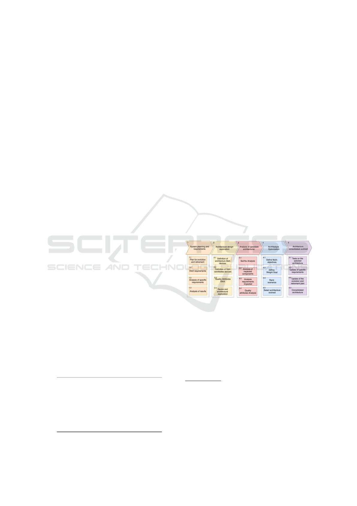
It consists of five phases and related criteria: plan-
ning, design of the evolved architecture (MCS, CMA,
AS), analysis of the candidate architectures for evolu-
tion(AI, RA, AA, AF), architecture optimization, and
evolved architecture consolidation. Each phase has a
set of four activities that guide designers in the devel-
opment of the evolution of architecture. Performing
the activities planned in each step feeds the next step,
as illustrated in Figure 1.
Figure 1: CAvA phases and activities.
The details of the proposed phases and activities are
the following:
Phase 1 Planning and System Requirements: The
survey of project requirements, specific requirements,
system architecture operation, and results of the anal-
yses performed on the architecture are carried out.
Activity 1.1 Plan Evolution and Retirement: The
stackholders, constraints, and limitations defined in
the project are lifted to meet the requirements of the
1
MCS: Multiple COTS selection.
2
AI: Ability to address incompatibilities.
3
AT: Available tool.
4
CMA: COTS modeling and architecture.
5
AS: Approach with norms standards.
6
RA: Requirements analysis.
7
AA: Analysis attributes.
8
AF: Analysis functionalities.
MODELSWARD 2021 - 9th International Conference on Model-Driven Engineering and Software Development
308

application. The information collected should direct
designers in the survey of modified design.
The Evolution and Retirement Plan (PEA) period-
ically evaluates the potential improvements and inclu-
sions of new features based on the technological ad-
vancement of S&A devices, starting the registration
of the ability to make modifications and inclusion of
new requirements.
Activity 1.2 Eliciting Requirements: The project
requirements are raised, including its functionalities
and details of the system in operation. Requirements
with the potential to be updated, or requirements that
can be included in the future, should be pointed out.
Operational design requirements that will be mod-
ified with the tradeoff/inclusion of candidate S&A de-
vices are identified and the specific requirements re-
lated to the devices are identified and selected. The
inclusion or updating of requirements can directly im-
pact the architecture, and a detailed analysis of the
specifications of the components and composition of
the system is performed in the next activity.
Activity 1.3 Analysis of Specific Requirements: The
specific requirements, features, and characteristics of
the current architecture are raised, identifying com-
ponents and functionality tied to design requirements.
The functional and non-functional requirements
of the architecture in operation are analyzed identify-
ing the relationship with the components, their char-
acteristics, and specific properties. For cases where
new requirements and functionality are included, the
designer must indicate the components added to the
architecture.
Activity 1.4 Analyze Simulation and Architecture
Results: The results of the simulations, tests, and val-
idation of the current system are obtained. System
quality attribute data is used as a reference to evalu-
ate evolution scenarios. The results obtained in sim-
ulations, bench tests, validation and architecture anal-
yses are used as a reference to evaluate the potential
scenarios of architectural evolution. This data is used
in the architectural model for further analysis of the
quality attributes, deployment, and current parameters
of the architecture.
Phase 2 Evolved Architecture Design: The S&A de-
vices of the current architecture and candidates are
surveyed to analyze functionality, hardware interface
and requirements.
Activity 2.1 Definition of Architecture S&A De-
vices: The potential S&A devices of the architecture
in operation that must be replaced are identified.
Designers receive new system requirements de-
mands that are linked directly to the tradeoff or inclu-
sion of new S&A devices, starting the selection and
definition of s&A devices that must be replaced in the
architecture.
Activity 2.2 Definition of S&A Devices Candidates:
The potential S&A devices that are candidates for re-
placement or inclusion in the operating system archi-
tecture are identified.
Designers conduct a technical market research on
the availability of S&A devices with physical char-
acteristics and properties compatible with the system
architecture and that meet the new requirements of the
project. After listing candidate devices, the designer
performs the modeling for further compatibility anal-
ysis.
Activity 2.3 Eliciting Quality Attributes: The soft-
ware and system quality attributes are elicited. The
physical, electrical, hardware interface, and software
components characteristics and properties are identi-
fied.
The quality attributes are structured based on
the ISO/IEC 25010(ISO/IEC, 2011) software quality
standard, consisting of 8 characteristics: functional
adequacy, reliability, performance efficiency, compat-
ibility, usability, safety, maintainability and portabil-
ity. Each characteristic has a set of sub-characteristics
and quality attributes that can be declared in the scope
of the architectural model for analysis of candidates
for further attributes valuation.
Activity 2.4 Architectural Exploration: Scenarios
are exploited based on functionalities and attributes,
evaluating the hardware interface between the system
and the candidate devices.
The exploration of architectures takes place in tree
tasks. In the first task there is the evaluation of COTS
candidates functionalities compatible with the old de-
vices and interface available in the architecture and
embedded platform. In the second task, a set of
scenarios are generated that cover the selected func-
tionalities and interface connections to the architec-
ture. Multiple COTS functionalities are combined
with candidates generating a set of scenarios. The
third task are Feature-friendly scenarios that have no
interface with the architecture are created with the ad-
dition of converter devices and connections.
Phase 3 Analysis of the Candidate Architectures for
Evolution: In this step the designer analyzes the gen-
erated scenarios, quality attributes, evaluating com-
pliance with requirements and impact of the tradeoff.
Activity 3.1 Analysis of Software and Hardware:
The designer performs the evaluation of the software
and hardware components of the generated scenarios
and selected architecture.
The scenarios generated are analyzed by identi-
fying hardware and software components, such as:
ports, communication and connection bus, tasks, pro-
cesses, and data type. S&A devices that internally
Approach for Evolving Sensing and Actuation Devices in Cyberphysical Systems Architectures
309

have a dedicated embedded system to perform spe-
cific signal handling functionalities, can encompass
architecture software components that until then were
run on the embedded system platform. With this, re-
distribution, removal or adjustments in processes and
tasks can add integration elements such as wrappers
and code glue that are analyzed in the next activity.
Activity 3.2 Analysis of Impacted Components: Im-
pact analyses are performed between scenarios and
selected architecture. The scenarios generated are
compared with the selected architecture identifying
the hardware and software components that were im-
pacted by the tradeoff. The survey of hardware com-
ponents, such as: interface, connections, power and
bus; software components, such as: connections, data
types, communication bus speed configuration, pro-
cesses, and threads that have had modifications to suit
the integration of the new device, being compared
with the selected architecture, identifying the differ-
ences and providing information extracted from the
scenarios.
Activity 3.3 Analysis of Impacted Requirements:
The survey and analysis of system requirements that
have been impacted by the exchange of S&A devices
is performed.
The analysis of the functional and non-functional
requirements that have been impacted by the change
of the S&A device occurs. The designer performs the
survey of attributes by type of characteristic, relating
to the defined requirements and performs the analysis
to identify potential risks in the scenarios explored.
Activity 3.4 Analysis of Scene Quality Attributes: In
this activity analyses of the quality attributes of the
scenarios are performed.
The result of the analyses obtained in activities 3.1
to 3.3 and the evaluation of specific attributes linked
to S&A devices, such as: accuracy, resolution, sig-
nal ratio, noise, sensitivity, hysteresis, output torque,
temperature operation are obtained to make up the set
of software and system quality attributes, being struc-
tured according to the definitions performed in activ-
ity 2.3.
Phase 4 Architecture Optimization: The quality at-
tributes of quantifiable scenarios are processed to
provide a set of parameters for each identified char-
acteristic type and attribute.
The attributes of the extracted scenarios and pa-
rameters of the quantifiable design requirements are
used in decision-making techniques such as Analyt-
ical Hierarchy Process (AHP). To properly set the
analysis, each attribute is defined with a minimum or
maximum value. For example, the attribute price is
defined with minimum value and processor capacity
with maximum value.
Activity 4.1 Definition Multi-objectives: The de-
signer defines which objectives are wanted to be eval-
uated based on the quality attributes elicited.
In this activity there is a definition of which char-
acteristics, subcharacteristics and quality attributes
the designer wants to evaluate in the scenarios. Each
scenario provides information about quantity of com-
ponents, device converters added, wrappers and con-
nections are impacted when compared with architec-
ture selected. In this way, the designer can also define
objectives considering the impact of the modifications
necessary to choose the scenario.
Activity 4.2 Definition of Weight Goal: The designer
defines the weights of each attribute based on objec-
tives he wants to evaluate.
According to the objectives defined for the explo-
ration of the scenarios, the designer defines weights
to the attributes to rank the scenarios.
Activity 4.3 Rank Scenarios: The ranking of sce-
narios is performed according to the objectives and
weights defined.
The ranking of the scenarios is performed by
defining which scenarios have achieved the best re-
sults and have met the requirements.
Activity 4.4 Select Architecture Evolved: The de-
signer selects the evolved architecture he wants to im-
plement.
Phase 5 Consolidate Evolved Architecture: In this
step tests and validation of the architecture are per-
formed with the new defined parameters. Require-
ments update and PEA are performed.
Activity 5.1 Tests and Validation: In this activity the
tests and validation of the evolved architecture are
performed.
In this activity, the use of techniques like Hard-
ware in-the-loop (HIL), Software in-the-loop (SIL),
and Processor in-the-loop (PIL) are suggested to ex-
tract behavior and performance data from the evolved
architecture in a real simulated environment. The test
results are used to feed, recursively, Phases 2 and 3,
refining the architectural model and performing new
analysis.
Activity 5.2 Project Requirements Update: textitIn
this activity, the specific design requirements obtained
from the architecture performance data and tests per-
formed are updated.
The new design requirements obtained from the
performance analysis of the evolved architecture with
the definition of the new deployment are validated.
The modifications and inclusion of new features that
culminated in the fulfillment of the new design re-
quirements are updated in the PEA for further eval-
uation of potential improvements in the system.
MODELSWARD 2021 - 9th International Conference on Model-Driven Engineering and Software Development
310
Activity 5.3 Evolution and Retirement Plan Update:
The evolution plan and PAE update take place, and
all changes made to the evolved architecture are doc-
umented.
All exchange records of S&A devices are col-
lected and updating project documents and require-
ments to be used as a reference.
Activity 5.4 Consolidated Architecture: The de-
signer upgrades the architecture to the new se-
lected architecture. New evolution’s/modifications
are based on the consolidated architecture.
The consolidation of the evolved architecture oc-
curs after the other proposed activities have been car-
ried out. The evolved architecture is defined as the
current system architecture, and its upgraded version
is indicated. New developments and modifications
can be made based on the consolidated architecture.
A tool named Automatic Evolution Wizard (AEW)
was developed to support the application of CAvA for
automatically explore and analyze possible scenarios,
specifically from phases 2 to 4. Phases 1 and 5 are
performed manually as they need multiple tools for
testing and validation that are not yet integrated.
4 CASE STUDY
To illustrate the architectural evolution approach pro-
posed in this paper it was applied to modify(evolute)
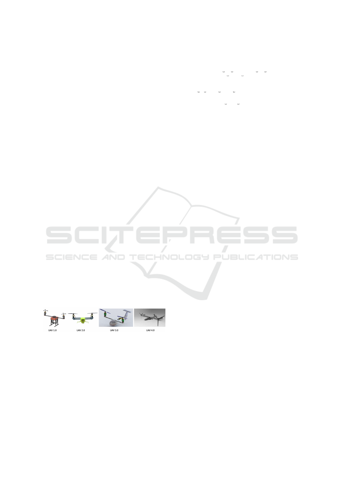
the architecture of an (UAV) projects. These projects
are part of a research effort called Provant, initiated
in 2012 in partnership between UFSC and UFMG.
Since the beginning of ProVant, Four aircraft proto-
types have been developed, as shown in Figure 2.
Each successor version aims enhance the problems
encountered in the predecessor project and also to add
new functionality.
Figure 2: ProVant prototypes versions.
Applying the proposed approach, the planning
step Step 1) begins with the survey of project require-
ments, defined specific requirements based on the ap-
plication and characteristics of the UAV of the current
version. Resulting in the architectural and require-
ments models, as well as the previous analysis per-
formed.
To exemplify, part of requirement model spec-
ification of UAV 3.0 with the ReqSpec language
file is shown in the Listing 4. The requirements:
UAV weight limit (lines 3-8); inlet power(lines 9-14).
Listing 1: Requirements model in ReqSpec language.
1 s yst em r e q uirem e n t s r e q s f o r Pr o Van t _ 3_0 [
2 d e s c r i p t i o n " Thes e a r e r e q u i r e m e n t f o r UAV"
3 r e qu i r eme n t R1 : "UAV w e i g h t l i m i t " [
4 v a l MaximumWeight = 1 . 2 kg
5 c a t e g o r y Q u a l i t y . Mass
6 d e s c r i p t i o n t h i s
7 " s h a l l b e w i t h i n w e i g h t o f " MaximumWeight
8 v a l u e p r e d i c a t e MaxWeight==# SEI : : W e i g h t L i m i t
9 s e e g o a l S CF g oal s . ng1 ]
10 r e qu i r eme n t R2 : "UAV i n l e t powe r " fo r UAVSystem [
11 v a l MaximumPowerBudget = 5. 0 W
12 c a t e g o r y Q u a l i t y . P e r f o r m a n c e
13 compute a c t u a l v o l t : P h y s i c a l : : V o l t a g e _Type
14 v a l u e p r e d i c a t e MaxPowerBudg et== P ow erB udg et
15 s e e g o a l S CF g oal s . g2 ]
Based on the ReqSpec model, the architecture candi-
date’s requirements are analyzed.
The UAV 3.0 architecture model is presented
in Listing 2. It is composed by three processors:
STM32F405, nrf51822 and and BEAGLEBONE
(ARM Cortex-A8). The software processes are:
RF_Firmware, STM32F405_Firmware, and BEA-
GLE_Firmware (lines 6-8). It includes devices and
buses (lines 9,10), connections (lines 11-13), and re-
sources/binding allocation (lines 15-17). As an exam-
ple, it has been selected to tradeoff the GY85 COTS
device, an IMU with three sensors: ADXL345 (ac-
celeration), ITG3205 (gyroscope), and HMC5883L
(magnetic field).
Listing 2: AADL model selected to evolve.
1 s yst em i m plem e n t a t ion Pro V ant _ 3 _0 . i mpl
2 subcomp on ents
3 STM32F405 : p r o c e s s o r STM32F405 ;
4 n r f 5 1 8 2 2 : p r o c e s s o r n r f 5 1 8 2 2 ;
5 BEAGLEBONE: p r o c e s s o r STM32F405 ;
6 RF_Fi rmwar e : p r o c e s s nRF51822_Firmware ;
7 STM32F405_Firmware : p r o c e s s STM32F405_Firmware ;
8 BEAGLE_Firmware : p r o c e s s B e a gle_F i r m w a r e . i m p l ;
9 GY85 : d e v i c e GY85 ;
10 . . . ( 1 0 a r c h i t e c t u r a l c o mpo n e nts )
11 c o n n e c t i o n s
12 C0 : bus a c c e s s STM32F405 . u a r t _ b u s −> UART;
13 .. . − − ( 1 7 c o n n e c t i o n s )
14 p r o p e r t i e s
15 A c t u a l _ P r o c e s s o r _ B i n d i n g => ( r e f e r e n c e
16 ( STM32F405 ) ) a p p l i e s t o STM32F405_Firmware ;
17 . . . −− ( 1 2 A l l o c a t i o n s a nd b i n d i n g s )
18 end P roV a nt_ 3 _ 0 . i m p l ; \ l a b e l { a a d l c o d e }
The COTS candidates that were surveyed must have
the same functionalities and be compatible in terms of
properties when compared with the selected device.
Candidates that do not have the functionalities to be
replaced totality can be combined with other candi-
dates.
In this example, the selected GY85 device has
three functionalities (accelerometer, gyroscope, mag-
netometer). Four devices surveyed can potentially
cover the functionalities and hardware interface com-
patibility. Another 8 devices cover partially the func-
tionalities, using more than one combined device.
In total, 12 candidate devices were elicited for aadl
modeling (CAvA library) to explore the scenarios, as
shown in Table 2.
Approach for Evolving Sensing and Actuation Devices in Cyberphysical Systems Architectures
311

Table 2: Candidate devices elicited for tradeoff.
Candidates Accel. Gir. Comp. Magnet. Baro. Temp.
GY85 (selected) O O O
BN055 X X X
ICM20948 X X X
ADIS16480 X X X X X
MPU9250 X X X
GY955 X X X
ICM20649 X X X
ADIS165052 X X X
LSM303DLHC X X
ADXL345 X
HMC6352 X
LSM303 X X
L3GD20H X
A video
1
is made available to show the AEW
tool usage within the present study. In Activities
2.1 and 2.2 the designer selects the AADL and Re-
qSpec models, and defines the implemented system to
be evolved. The tool reads the models, analyzes the
functionality of the devices selected for replacement,
and search for candidate devices. Next, in Activities
2.3 and 2.4, it presents the list of devices to be re-
placed and create possible tradeoff scenarios.
Activities 2.3 and 2.4 are performed generating
the set of scenarios explored in tree sequential tasks,
based in functionalities and quality attributes from
hardware interface characteristics. The first task gen-
erates scenarios with candidates and combinations of
candidates that fulfill selected functionalities. The
second stage generates scenarios with hardware in-
terfaces (ports and bus) compatibles. Candidates
with multiple hardware interfaces compatible gener-
ate alternatives of scenarios. The third stage gener-
ates scenarios without hardware interfaces compati-
ble, adding a converter device in hardware interface
for integration with the architecture. The focus is to
consider as many scenarios as possible to be analyzed
and further rank them.
Considering the selection of devices that have the
same hardware interface as the GY85 and function-
alities, the approaches described in the related works
would be able to also solve this challenge due their
specific focus on properties. However, evaluating the
hardware interface candidates, only 4 devices within
the 12 elicited are enabled, reducing the exploration
of scenarios and limiting the space project and multi-
ple objectives.
In total, applying CAvA approach, 126 scenar-
ios were generated containing the comparative anal-
ysis with the selected architecture. The CAvA ap-
proach expands the generation of scenarios based
on evaluation of functionalities, compatible and non-
compatible hardware interfaces.
The AEW tool presents the created scenarios and
changes details to integrate the candidate e combi-
1
https://youtu.be/v1kZBcd4yVM
nations. In the Listing 4 shows the changes from
scenario with MPU9250 device tradeoff, declaration
added to integrate the device (lines 1-4), changes in
connections (lines 5-7), device that is deleted from
the architecture (lines 8,9), functional suitability from
GY85 to MPU9250 (lines 10,11), and information to
add a wrapper in C11 connection to provide compati-
bility (lines 12,13).
Listing 3: AADL model selected to evolve.
1 d e c l a r a t i o n ad d ed :
2 sub c omp o n ent MPU9250
3 sub c omp o n ent wrapper_DOF6_to_DOFS
4 c o n n e c t i o n C23
5 d e c l a r a t i o n cha n g e d :
6 c o n n e c t i o n C11
7 c o n n e c t i o n C4
8 d e c l a r a t i o n d e l e t e d :
9 sub c omp o n ent GY85
10 F u n c t i o n a l S u i t a b i l i t y :
11 MPU9250 . i mpl : GYROSCOPE,ACCELEROMETER, COMPASS
12 M ess age s :
13 Wr ap pe r was u s e d in C11 : MPU9250 . DOF6−>STM32F405 . DOFS
Analyzes of candidate scenarios, shown in Phase
3, are processed identifying modifications and im-
pacts on architecture components, quality attributes
and requirements. Therewith, the results compose the
quality attributes that are analyzed and structured ac-
cording to characteristic and sub-characteristics, de-
scribed in Activity 3.4, to support the architecture op-
timization.
And finally, the architecture optimization is con-
templated in AEW tool. The attributes and result
of scenarios analysis are presented following qual-
ity characteristic and normalization of ratings, from
0 to 1, adjusting values measured on different scales,
where the designer defines the weights for each de-
sired objective, as defined in Activities 4.1 and 4.2.
In total, 22 attributes are modeled. After the set def-
initions, the tool generates the ranking of scenarios,
Activity 4.3. The designer can select the scenario he
wants to implement and generate the AADL model of
the evolved architecture, Activity 4.4.
The UAV 3.0 attributes and result of scenarios
analysis as number of connections, devices, modifi-
cations, features and properties are normalized, from
0 to 1, and are presented to the designer who further
performs the decision-making to calculate the rank-
ing of scenarios. For the present study, the objec-
tives and related weights defined to architecture evo-
lution are better precision, lower noise signal, of the
data provided from gyroscope(x0.3) and accelerome-
ter(x0.3), lower hardware conversor(0.2) and software
wrapper(0.2) added as shown in Figure 3. In total, 34
scenarios demonstrate better results than original ar-
chitecture. The best obtained scenario was with the
ADIS16480 device integrating multiple functionality
with the least impact of change in architecture. How-
MODELSWARD 2021 - 9th International Conference on Model-Driven Engineering and Software Development
312
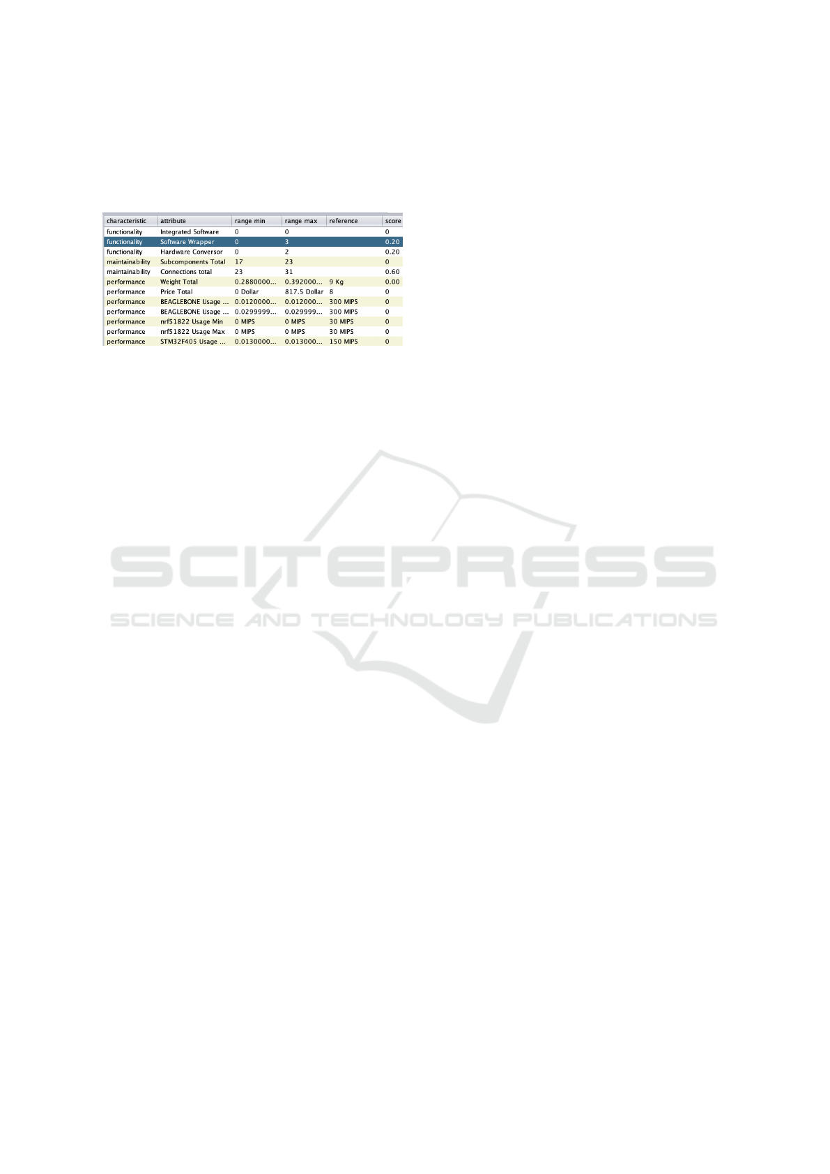
ever, this scenario presented highest cost, increased
area, power consumption, and also increased data
consumption on the SPI bus compared to GY85 de-
vice presented in the tool’s analysis results.
Figure 3: Weight definition to scenarios ranking.
The result of the analysis is made available in
a .csv file where the designer evaluates the details
of changes, quality attributes with related goals, and
analyses results from selected scenario. After test-
ing and validation of the architectural model, Activity
5.1, the designer updates the design, evolution plan
and retirement requirements described in Activities
5.2 to 5.4. The architectural model is consolidated
and represents the current architecture, as described
in Activity 5.4, the results of the analyses, tests, ad-
justments, and new requirements are updated.
5 CONCLUSIONS AND FUTURE
WORK
CavA suggests a set of phases and activities that, in
cooperation with additional model analysis tools, help
to mitigate these risks and limitations, automatically
evaluating the impacts of modifications using quality
attributes declared in the AADL model. Comparing
with the related works, CAvA expands the capacity to
evaluate scenarios based on the functionality, compat-
ible and non-compatible hardware interface, enabling
the exploration of emerging technologies.
A difficulty in tracking functionalities suitability
between requirements defined in ReqSpec and AADL
models was identified. ReqSpec does not support the
declaration of functionalities, demonstrating a gap to
support functionality that can be further investigated.
REFERENCES
Aleti, A., Bjornander, S., Grunske, L., and Meedeniya, I.
(2009). Archeopterix: An extendable tool for archi-
tecture optimization of aadl models. In 2009 ICSE
Workshop on Model-Based Methodologies for Perva-
sive and Embedded Software, pages 61–71.
Barbacci, M., Carriere, S., Longstaff, T., Weinstock, C., and
Feiler, P. (1998). Steps in an architecture tradeoff anal-
ysis method: Quality attribute models and analysis.
Technical report, CMUSEI.
Bass, L., Clements, P., Kazman, R., et al. (2013). Software
architecture in practice.
Bengtsson, P., Lassing, N., Bosch, J., and van Vliet,
H. (2004). Architecture-level modifiability analysis
(alma). Journal of Systems and Software, 69(1-
2):129–147.
Feiler, P. H., Delange, J., and Wrage, L. (2016). A require-
ment specification language for aadl. Technical report,
CMU/SEI.
Garg, R. (2017). A systematic review of cots evaluation and
selection approaches. Accounting, 3(4):227–236.
Grau, G., Carvallo, J. P., Franch, X., Quer, C., et al. (2004).
Descots: a software system for selecting cots compo-
nents. In Proc.. 30th Euromicro Conf., 2004., pages
118–126. IEEE.
Ibrahim, H., Elamy, et al. (2011). Unhos: A method for un-
certainty handling in commercial off-the-shelf (cots)
selection. Int. Journal of Energy, Information & Com-
munications, 2(3).
ISO/IEC (2011). Iso/iec 25010: 2011 systems and soft-
ware engineering–systems and software quality re-
quirements and evaluation (square)–system and soft-
ware quality models.
Kazman, R., Klein, M., Barbacci, M., Longstaff, T., Lipson,
H., and Carriere, J. (1998). The architecture tradeoff
analysis method. In Proc. 4th IEEE Int. Conf. on En-
gineering of Complex Computer Systems, pages 68–
78. IEEE.
Lee, E. A. and Seshia, S. A. (2016). Introduction to em-
bedded systems: A cyber-physical systems approach.
MIT Press.
Mohamed, A., Ruhe, G., and Eberlein, A. (2007). Cots
selection: Past, present, and future. In 14th IEEE
Int. Conf. and Works. on the Eng. of Computer-Based
Systems (ECBS’07), pages 103–114.
Mohamed, A., Ruhe, G., Eberlein, A., et al. (2007). Mi-
hos: an approach to support handling the mismatches
between system requirements and cots products. Re-
quirements Engineering, 12(3):127–143.
Ncube, C. and Maiden, N. A. (1999). Pore: Procurement-
oriented requirements engineering method. In Int.
workshop on component-based software engineering,
pages 130–140.
Procter, S. and Wrage, L. (2019). Guided architecture trade
space exploration: Fusing model based engineering
design by shopping. In 2019 ACM/IEEE 22nd Int.
Conf. on Model Driven Eng. Languages and Systems,
pages 117–127.
Ross, J. A., Murashkin, A., Liang, J. H., Antkiewicz, M.,
and Czarnecki, K. (2019). Synthesis and exploration
of multi-level, multi-perspective architectures of au-
tomotive embedded systems. Software & Systems
Modeling, 18(1):739–767.
Approach for Evolving Sensing and Actuation Devices in Cyberphysical Systems Architectures
313
