
Real-time Electrode Misalignment Detection Device for RSW Basing
on Magnetic Fields
D. Ibáñez
1a
, E. García
2b
, J. Martos
1c
and J. Soret
1d
1
Dept. of Electrical and Electronic Engineering, University of Valencia, Burjassot, Valencia, Spain
2
Ford Valencia, 46440, Valencia, Spain
Keywords: Resistance Spot Welding, Detection, Hall Effect Sensors, Electrodes, Misalignment, Magnetic Field,
Simulation.
Abstract: Electrodes misalignments are considered one of the most important mechanical factors involved in RSW
(Resistance Spot Welding). Misalignment causes quality problems as undersized weld, expulsions or
nonrounded-weld. Man-power needed in the automotive production lines is increased so as to repair the lack
of quality, which means an increase in the cost of production. Consequently, an implantable solution for the
automotive industry should be developed in order to detect misalignment when this happens. This research
gives an answer by measuring the electrode misalignment by means of the generated magnetic field for the
electrodes. The proposed method is validated by Multiphysics simulation measurement. Finally, this method
is put into practice by creating a device tested in an automotive production line at the assembly and body plant
in Ford Valencia. Together with the device, a communication system is implemented to carry out predictive
management. This research initiates a novel line of research for the early and online detection of
misalignment problems in welding guns.
a
https://orcid.org/0000-0002-3917-9875
b
https://orcid.org/0000-0002-4210-9835
c
https://orcid.org/0000-0002-8455-6369
d
https://orcid.org/0000-0001-8695-6334
1
INTRODUCTION
The resistance spot welding process bases its
operation on a current flow from the tip of the upper
electrode between the metals to be welded to the tip
of the lower electrode. When the current circulates
through the metals, and due to Joule's law, the heat
generated melts the metals forming a weld joint
between the metal sheets through the fusion and the
result is a strong weld between sheets without
additional substances. Therefore, the growth of the
weld (welding nugget) depends on the density of
welding current, the welding time, the force exerted
by the electrodes on the sheets and the area of the
electrode tip (Aravinthan et al., 2011)
This dependence is different depending on the
parameter, since the time and the current make the
welding, while the pressure and the area of the
electrode tip have a direct relationship with the final
quality of the welding.
Misalignment of the electrodes causes a
variation in the contact area between the electrode
tips. The alignment of electrodes can be classified
into three types depending on their orientation. The
electrodes can be perfectly aligned, axially
misaligned or angularly misaligned, as shown in
Figure 1 (Zhang et al., 2005).
Figure 1: Types of electrode misalignment RSW.
142
Ibáñez, D., García, E., Martos, J. and Soret, J.
Real-time Electrode Misalignment Detection Device for RSW Basing on Magnetic Fields.
DOI: 10.5220/0009820801420149
In Proceedings of the 17th International Conference on Informatics in Control, Automation and Robotics (ICINCO 2020), pages 142-149
ISBN: 978-989-758-442-8
Copyright
c
2020 by SCITEPRESS – Science and Technology Publications, Lda. All rights reserved
Different studies have shown the alignment of the
electrode plays an important role in the geometry of
the welding point, Figure 2, in addition the
misalignment of the electrode causes expulsion,
which leads to poor welding zones Tang et al.,2003),
(Charde,2012).
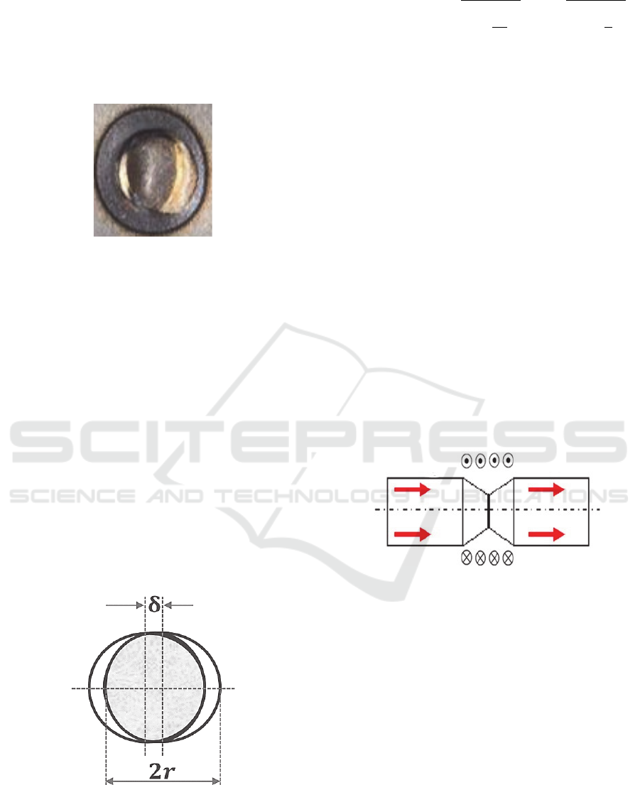
Figure 2: Poor-quality spot causes by misalignment.
Some authors have proposed different methods
for detecting misalignment using image processing
methods, by which they are able to determine the
direction and angle of misalignment with good results
(Li et al.2019). The main problem presented by this
method is the cost of implementation for a high
production line with many welding guns. Therefore,
there is not a viable method for detecting
misalignment in this type of production lines.
Due to the reasons mentioned above, there is a
need to investigate a simple and economical method
for the detection of misalignment, since what is
sought is that it can be used in the high-production
automotive industry.
The theoretical basis of this method is laid on the
variation of the current density at the tip of the
electrode. Specifically, what is intended with this
method is to identify the change in current density as
the misalignment appears.
Figure 3: Geometric model for calculating contact area
due to axial misalignment.
When the electrodes are misaligned, as shown in
Figure 3, the contact area (Ca) of the electrode tips
varies according to the equation 1.
𝐶
2𝑟
sin
1
𝛿
2𝑟
𝛿
𝑟
𝛿
2
where Ca is the contact area of the electrodes, r
is the radius of the electrode and δ is the amount of
misalignment.
It can be seen from the equation that the
reduction of the contact area is strongly correlated
with the axial misalignment.
From the Ampère's Integral Law can be obtained
the relationship between the magnetic field (B) and
the current density. This law relates the magnetic field
intensity to its source, the current density.
𝐵
⃗
∙𝑑𝑙
⃗
µ
𝐽
⃗
∙𝑑𝑆
⃗
µ
𝜀
𝐸
⃗
∙𝑑𝑆
⃗
Where the magnetic field is described by the
variable B, the current density by J and the electric
field by E.
Following the equation 2, it can be affirmed that
if the current flows through the electrodes, and
therefore there is a current density, a rotational
magnetic field around the electrodes appear and the
rotor of the magnetic field points in the same
direction that the current density, this behaviour is
represented in Figure 4.
Figure 4: Generated Magnetic Field.
As a result, basing in this equation, it can be
affirmed that when electrodes are misaligned, the
contact area of the electrodes decreases, which
produces a raising on the current density and
consequently a magnetic field higher than which is
generated with a correct electrode alignment.
2
MISALIGNMENT DETECTION
METHOD
As shown in the previous section, a possible
relationship between the magnetic field generated by
the short-circuited electrodes and their misalignment
can be deduced mathematically. The proposed
method for the detection of the misalignment is
Real-time Electrode Misalignment Detection Device for RSW Basing on Magnetic Fields
143
based on the measurement of the magnetic field in
the contact plane of the electrodes.
The measurements should be carried out in such a
way that a value is obtained for determining the
direction of the misalignment of the electrodes.
For this, it is postulate that if the contact plane is
divided into the Cartesian axes and measurements are
made at different distances from the centre of the
ideal contact surface of the electrodes, could be
detected the misalignment of the electrodes and its
direction.
This means that if the magnetic field can be
measured in both Cartesian axes, both in positive and
in negative, it will be possible to determine the
difference of the magnetic field generated by the
misaligned electrodes in comparison with the one
generated by the perfectly aligned electrodes.
As it is a novel hypothesis, due to the fact that
other researchers haven´t published anything related
to the relationship between the magnetic field and the
misalignment, it is fundamental to demonstrate it.
Firstly, performing a validation by means of
simulation of the physical phenomenon, to verify that,
in fact, the mathematical assumption is fulfilled.
For the validation of this method, software of
simulation of the physical phenomenon based on
magnetic field theory is used.
Once the hypothesis has been validated for the
proposed method, a device would be developed for
taking measurements in an industrial environment,
capable of determining the differences between
simulation and real experimentation to finally design
an automatic system for detecting problems of
alignment of welding electrodes in real time.
3
MATERIALS AND METHODS
For the analysis of the behaviour of the magnetic
field depending on the state of the misalignment, a
physical phenomenon simulation software is drawn
on. The simulations are carried out for the symmetry
of an F- type electrode (ISO 5821, 2007) with the
following data:
•
Current flowing through the electrode: 8 kA.
•
Diameter of the electrode tip: 6mm.
•
Electrode body diameter: 20 mm.
•
Cone height: 5mm.
These simulations are performed simulating a
current flowing between the electrodes shorted. To
obtain the relationship between misalignment and
generated magnetic field.
During this validation, three tests will be
performed. In the first one, the magnetic field
generated for an electrode in which δ = 0 mm, i.e., a
perfectly aligned electrodes, is simulated. In the
second, the value of δ is increased up to 1mm and the
magnetic field is simulated, comparing the values of
both cases. Finally, the value δ is increased again up
to 2mm and the simulation is carried out, comparing
all the obtained values.
For each of the cases, two simulations are carried
out. In the first simulation, the values of the magnetic
field are collected depending on the distance on the x-
axis to the centre of the electrode. These values are
simulated for both the contact plane of the electrodes,
z = 0 mm, as for planes situated z = 10mm and z = -
10mm.
In the second simulation, the data is acquired in
this case as a function of the displacement in the z-
axis. In this simulation, two data curves are obtained:
the variation of the magnetic field on the z-axis when
x = 20mm and the variation of the magnetic field on
the Z-axis when x = -20mm.
4
MAGNETIC FIELD
SIMULATION
This section shows the results of the different simulat-
ions carried out as described in the previous section.
4.1
δ=0mm
As mentioned, simulations are carried out for three
different scenarios. In this first case, two electrodes
perfectly aligned are simulated, δ=0 mm and S=
50.26 mm
2
. This first case points what is the ideal
value of the magnetic field generated by the
electrodes. The following cases should therefore be
compared with this to determine if there is certainly a
relationship between the misalignment and the
generated magnetic field.
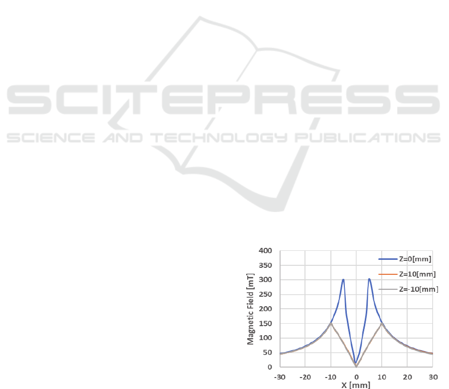
Figure 5: Magnetic Field Generated for aligned electrodes.
X-axis displacement.
ICINCO 2020 - 17th International Conference on Informatics in Control, Automation and Robotics
144
From this simulation, the data represented in
Figure 5 and Figure 6 are obtained. As it can be seen,
both in the data of Figure 5, which shows the
evolution of the magnetic field on the x axis, and the
one of Figure 6, which shows the evolution of the
magnetic field in the y-axis, there is a symmetry in
the generated magnetic field.
Hence, this means that when measuring at the
same distances from the centre of the generated
magnetic field, the same value is obtained. This point
is very important because what is sought in this study
is to be able to determine the misalignment but also
the direction of it.
In addition, this data also shows how the Ampere
law is fulfilled. By analysing the three curves of
Figure 7, it can be observed how those taken on the
planes z = -10mm and z = 10mm, present a lower
magnetic field value. This is because at this height,
the surface through which the intensity flows are S
= 314.15mm
2
. This makes the current density lower
and therefore the magnetic field is lower too
Figure 6: Magnetic Field Generated for aligned electrodes.
z-Axis displacement.
4.2
δ=1mm
In this second case, electrodes with a displacement
of the upper electrode of 1mm are simulated, that is,
δ = 1mm. Using equation 1 it can be calculated that
the contact surface for this case will be S = SꞏCr =
50.26ꞏ0.7623= 38.31 mm
2
.
Therefore, according to the hypothesis, the
magnetic field generated by the electrodes must be
higher since the current density increases.
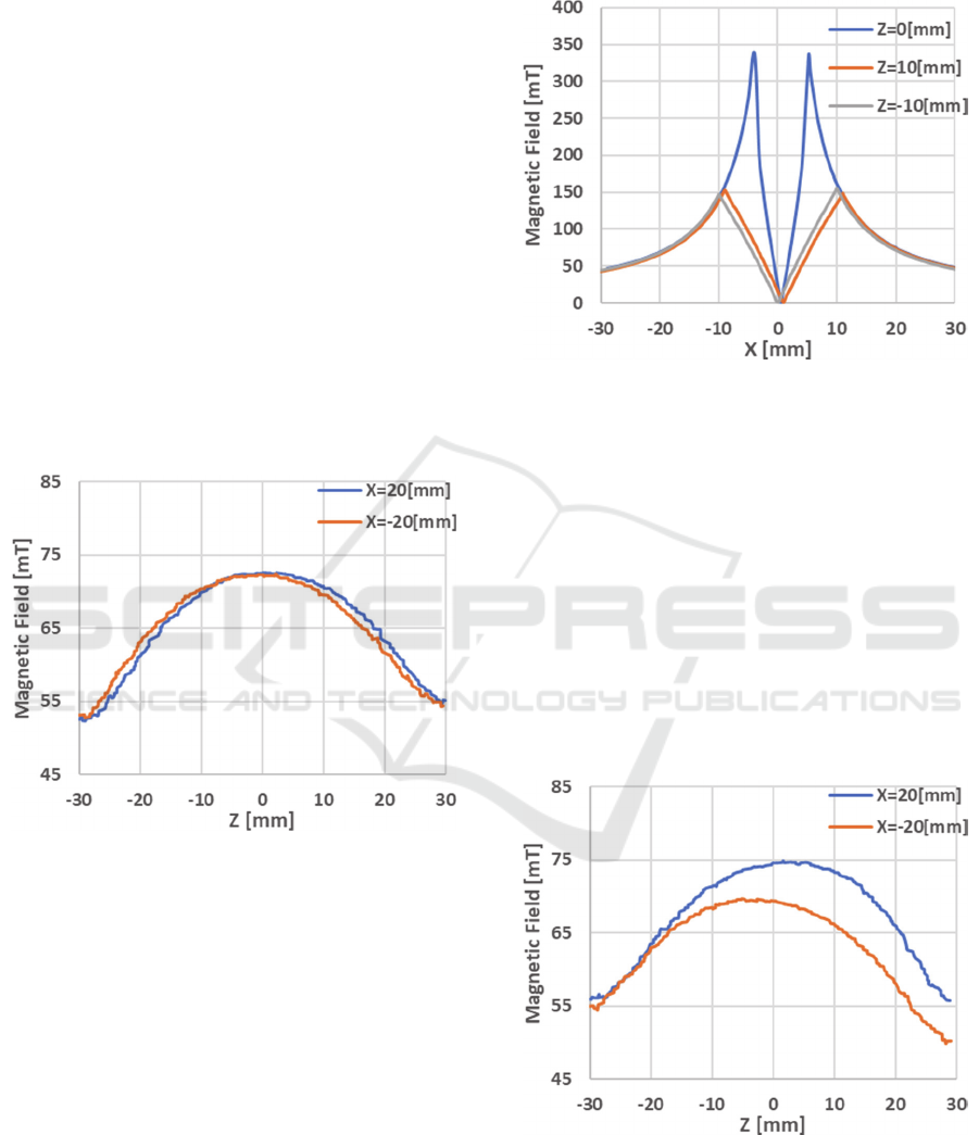
Figure 7 shows how, as expected, the simulated
magnetic field is greater than the magnetic field of
Figure 5. The maximum value of the generated
magnetic field is 340 mT, which represents an
increase in the magnetic field by approximately 111%
compared to the field generated by the perfectly
aligned electrodes.
Figure 7: Magnetic Field Generated for electrodes with
δ=1mm. X-axis displacement.
To make the comparison between the different
cases, the data is analysed at 20mm from the centre of
the magnetic field for the perfectly aligned electrodes.
This centre is shown in the graphs as the zero of the
coordinate axes. This analysis is done in a more
graphical way observing the Figure 6 and 8 that
represents the displacement in the Z-axis, since the
data represented in it are those corresponding to the
distances 20mm and -20mm.
If the data of x = 20mm and x = -20mm are
taken at the time when z = 0mm, it can be observed
that for the aligned electrodes this takes a similar
value of 72 mT approximately.
Figure 8: Magnetic Field Generated for electrodes with
δ=1mm. z-Axis displacement.
On the other hand, with the data collected for this
second case, it is observed that for x = 20mm the
value of the magnetic field is equal to 74.5 mT, while
Real-time Electrode Misalignment Detection Device for RSW Basing on Magnetic Fields
145
for x = -20mm the magnetic field is equal to 69,5mT.
This means that while in the first case the difference
between x = 20mm and x = -20mm is 0 mT, in the
second case this difference increases significantly up
to 5 mT.
It is also important to point out that because of the
fact that one of the electrodes has moved but the other
has been fixed, the centre of the magnetic field has
been shifted 0.5 mm. This also rise the difference
between the values in the x positive and negative x.
4.3
δ=3mm
In this last case the misalignment of the electrodes
increases δ up to 3 mm. This supposes a misalignment
of 50% of the maxim misalignment. This last
simulation helps to determine in a more reliable way
if it is possible to differentiate different states of
misalignment.
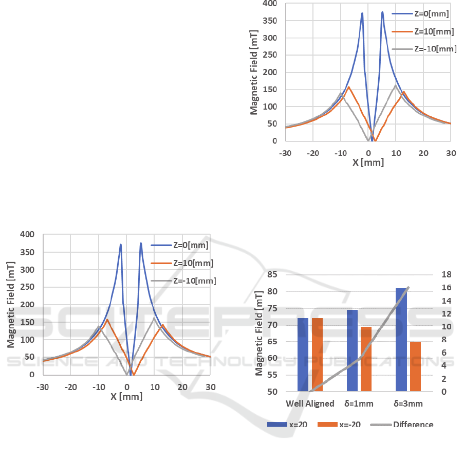
Figure 9: Magnetic Field Generated for electrodes with
δ=2mm. X-axis displacement.
In this case, using equation 1 again, the actual
contact surface of the electrodes can be calculated.
Since δ has increased to 2mm, the ratio between the
ideal surface and this new surface decreases to
0.5309. Therefore, the current surface is 26.68 mm
2
.
As in the previous case, it can be seen in Figure 9
that the maximum magnetic field generated is higher
than the other two cases, taking a value of 376 mT.
This represents an increase of 123% and 111%
respectively.
Following in this case the previous analysis about
the measurement differences between x = 20mm and
x = -20 can be seen, as in the previous result, that there
is no symmetry. For x = 20mm a value of 81 mT is
recorded, while for x = -20mm a value of 65mT is
recorded.
Figure 10: Magnetic Field Generated for electrodes with
δ=2mm. X-axis displacement.
Therefore, in this third case it can be seen how the
difference between both measures increases again
while the misalignment increases too, going from a
difference of 0 mT for the misaligned electrodes to a
difference of 16 mT
Figure 11: Summary of simulation result.
Finally, Figure 11 summarizes the most relevant
values of this validation by simulation. Then, the
results show that there is a strong relationship
between the generated magnetic field and the
alignment of the electrodes. So, the hypothesis has
been validated.
5
SIMPLE DEVELOPMENT OF A
DEVICE FOR THE DETECTION
Once the hypothesis has been validated, it is
necessary to study how this new method can be
applied to the high production industry of the
automobile.
ICINCO 2020 - 17th International Conference on Informatics in Control, Automation and Robotics
146
As it has been explained, it is necessary to make
measurements of the magnetic field in the contact
plane of the electrodes. Therefore, it is necessary to
perform four measurements of the magnetic field, two
for each of the axes x-y. For this, it is necessary to
located sensors capable of performing these
measurements at x = 20mm, x = -20mm, y = 20mm
and y = -20mm.
In this case, two PCB are manufactured, one in
which four low-cost hall effect sensors are located,
which will be where the measurement is made. In this
first PCB it is designed with a circular hole in the
middle, so that the four hall effect sensors are
distributed to perform measurements on the two
cartesian axes.
In the second PCB the microcontroller used to
control the signals collected by the sensors is located.
To isolate the two PCBs, a 3D printed PCA
encapsulation is performed. This design is made to
optimize costs and increase the robustness of the
design.
This device is designed so that the electrodes can
be closed and positioned in the middle of the four
sensors. Once located in that position, a current is
passed between the short-circuited electrodes and the
sensors measure the generated magnetic field.
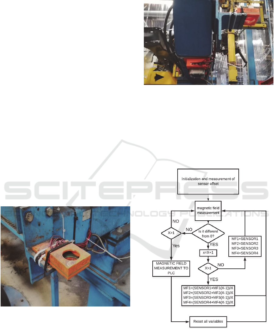
Figure 12 shows the location on the real welding
line of the PCB on which the Hall Effect sensors are
mounted.
Figure 12: Actual PCB location for magnetic field
measurement.
This measured magnetic field data is sent to the
second PCB where the microprocessor that manages
these signals is located. There the voltage values
measured by the sensors are converted to magnetic
field units.
Figure 13: Actual PCB location for collection of the data.
Figure 13 shows the situation of the PCB, in
which the microprocessor is located, in the actual
welding line.
The signal management is carried out following
the flow chart of Figure 15. Once the microcontroller
is initialized, a first measurement of the magnetic
field is made to determine the offset of the sensors,
thus eliminating the possible differences between the
measurements.
Figure 14: Operating flow chart.
Once this action is carried out, the four sensors
begin to record the magnetic field value, if the
measured magnetic field is zero, the microcontroller
does not perform any calculation. Once the electrodes
are short-circuited and generate a magnetic field, the
Real-time Electrode Misalignment Detection Device for RSW Basing on Magnetic Fields
147
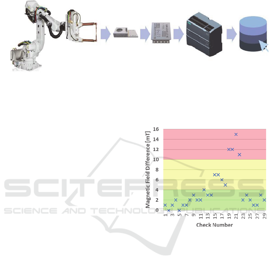
Figure 15: Measurement process flow.
microcontroller begins to register the values by
calculating at all times the average value of the
magnetic field measured in that period of time, so that
the possible peaks that could appear are reduced by
Use the average.
When the electrodes stop conducting current, the
sensors re-measure the absence of magnetic field
and at that time, the microcontroller sends the values
to the PLC.
After communication with the PLC, the variables
are reset to 0 and the measurement is restarted
waiting again for the magnetic field generated by the
electrodes in short circuit.
6
REAL-TIME CONTROL
APPLICATION
Once a device capable of detecting the magnetic
field has been developed, and therefore, the problems
of alignment of the electrodes in the welding clamps,
it is necessary to develop a final system capable of
carrying out preventive maintenance on the actual
welding line.
In such a way that patterns of misalignment
behaviour and work limits are established based on
history and experimentation. To do this, once the
process described in Figure 14 is finished, when the
data is already in the PLC, this data is stored in a
database and sent to a web server. This whole process
can be summarized in Figure 15.
In this case, in order to reduce the number of
variables on which to perform the analysis, the four
variables of each of the sensors are reduced by only
two.
These two variables are calculated by subtraction
between the sensors placed antiparallel, therefore, the
two final variables will represent the displacement of
the centre of the magnetic field on the X and Y axes,
eliminating the absolute value of each of the four
sensors.
Starting from the established values of the
simulation first and after the values stored in the
history, the alarm and pre-alarm levels for each of the
Cartesian axes can be established. As shown in figure
16.
Figure 16: Example of alarms based on simulation.
Currently, this whole real-time medicine process
is installed in a welding line. This application allows
to obtain the data of each check in the attempt in
which it is performed.
This last part of the investigation is still in an
exact process of validation, since it is convenient to
test all the cases and the real behaviour of a welding
clamp, beyond the simulation results.
7
CONCLUSION
This article tries to give a solution to this important
problem of misalignment in the electrodes of the
welding guns. This problem directly affects the costs
of production of automobile manufacturing, so it is
mandatory to find a solution that can be implantable,
i.e., a solution that does not involve a high cost of
implementation. This article responds positively,
ICINCO 2020 - 17th International Conference on Informatics in Control, Automation and Robotics
148

presenting a method for detecting the misalignment
by magnetic fields.
For the method validation, mathematical
calculations and simulations are used, in which it is
observed how, unequivocally, there is a strong
relationship between both factors.
Finally, a device for measuring the magnetic field
is proposed, this device is composed of four hall
effect sensors managed by a microcontroller. For the
validation of the sensor, tests in a line of production
of the automobile in Valencia Body and Assembly
plant are carried out.
Although the data collection is not yet extensive
enough, a historical data collection is begun to
monitor the behaviour of the magnetic field generated
by real misaligned electrodes.
In future investigations, the data obtained in the
actual welding line should be analysed. Based on
these results, a possible update of the method and the
designed device should be performed.
In addition, an exhaustive study of the influence
of the existing noises on the production lines and
their influence on the measures taken must be made.
ACKNOWLEDGEMENT
The authors wish to thank Ford España S.A, in
particular, the Almussafes factory for their support in
the present research.
REFERENCES
Aravinthan, A. and Nachimani, C. 2011. Analysis of Spot
Weld Growth on Mild and Stainless Steel. Welding
Journal August 2011: 143-147.
Claude Cohen-Tannoudji; Bernard Diu et Frank Laloë
1977. Mécanique Quantique, vol. I et II. Paris:
Collection Enseignement des sciences (Hermann).
Richard Feynman 1974. Feynman lectures on physics
Volume 2. Addison Wesley Longman.
ISO 5821 [2007] Resistance Spot Welding Electrode
Caps.
Tang, He (Herman) & Hou, W. & Hu, S.J. & Zhang,
H.Y.& Feng, Z. & Kimchi, Menachem. 2003.
Influence of welding machine mechanical
characteristics on the resistance spot welding process
and weld quality. Welding Journal. 82. 116/S-124/S.
Charde, Nachi Mani. 2012. Effects of electrode
deformation on carbon steel Weld. International
Journal of Advance Innovation, Thoughts and Ideas. 1.
8.
Li, Yanqing & Tang, Guokun & Ma, Yongsheng &
Shuangyu, Liu & Ren, Tao. (2019). An electrode
misalignment inspection system for resistance spot
welding based on image processing technology.
Measurement Science and Technology. 30.
10.1088/1361- 6501/ab1245.
Zhang, H. & Senkara, J. 2005. Resistance welding:
Fundamentals and applications.
Walker, Jearl; Halliday, David; Resnick, Robert 2014.
Fundamentals of physics (10th ed.). Hoboken, NJ:
Wiley. p. 749.
Real-time Electrode Misalignment Detection Device for RSW Basing on Magnetic Fields
149
