
Optimization of Coupling Efficiency of Fiber Optic Rotary
Joint by Ray Tracing
Chun-Han Chou
a
, Rou-Jhen Chen, Hsin-Yi Tsai
b
, Kuo-Cheng Huang and Chih-Chung Yang
National Applied Research Laboratories, Taiwan Instrument Research Institute, 20 R&D Rd. VI, Hsinchu Science Park,
Hsinchu City 30076, Taiwan
Keywords: Fiber Optic Rotary Joint, Coupling, Manufacture Error, Dove Prism, Tolerance Analysis.
Abstract: In the paper, a misalignment and field magnification tolerance analysis for the coupling efficiency of fiber
optic rotary joint was presented. The analysis consisted of output position deviations from different
wavelengths, dove prism manufacturing errors, light tilt and decenter errors. It helped manufacturers easily
defined component specifications and assembly tolerances for fiber optic rotary joint. The 2 mm spot size was
best suited for current assembly tolerances. The 2 mm beam diameter of coupling efficiency was over 80% in
the tilt error ±10 arcmin and decenter error ±250 μm. In the future, we could create a FORJ system according
to the simulation parameters. The practice experiment data would compare to our simulation results that used
to prove our simulation results.
1 INTRODUCTION
Currently, the automation industry was growing
rapidly. It required a large number of signal
transmission components to connect each part of the
component. The fiber optic rotary joint(FORJ) was
used to transmit signals across rotary interface (Jia,
Jing, Zhang, Wang, Tang and Zhang, 2005). FORJ was
widely used in the lot of fields of remotely operated
vehicles, oceanographic winches, cable reels, towed
arrays, dipping sonar, undersea telemetry and Robotics
etc. The traditional multi-pass of FORJ required high
precision alignment to reduce signal coupling losses
(Liu, Zhu, Jiang and Gao, 2013). Due to manufacturing
difficulties, people began to look for another way to
solve the problem. People began to use the different
ways of C-lens (Jia, Jing, Zhang, Zhou, Zhang and
Tang, 2005) and GRIN lens (Shi, Klafter and Harstead,
1985). Even these methods could reduce the coupling
loss, but it was difficult to continuously transmit multi-
signals when the interface continue rotation. Another
group of People used other ways of multi-reflector
mirror (Liu and Chen, 2006), diffractive element
(Mathias and Sverker, 1999) and symmetrical optical
system (DENG, ZHOU and LIU, 2001) etc. These
methods could overcome the problem of multiple
a
https://orcid.org/0000-0003-2460-5875
b
https://orcid.org/0000-0001-8275-6132
signal transmission, but these systems had the
disadvantages of large system size and high cost etc.
Previously problems were solved until people used
dove prism for FORJ. The structure of FROJ composed
of fiber array, collimator lens and dove prism. The
system was smaller than the multi-mirror and
symmetrical optics, and it continued to transmit
multiple signals as the interface continued to rotate
(Jia, Yu, Jing, Zhang, and Zhang, 2008). The key factor
of the dove prism type of FORJ was the manufacture
error of dove prism and the assemble tolerance of the
system (Shapar, 2018). Enoch group used exact ray
trace to calculate the interferometric Dove prism
tolerance to manufacturing errors, but they didn’t
mention the prism alignment tolerance (Gutierrez-
Herrera and Strojnik, 2008).
Therefore, we presented a misalignment and field
magnification tolerance analysis for the FORJ
coupling efficiency. It helped producers easily defined
element specifications and assembly tolerances for
FORJ. The tolerance analysis had the output position
deviation of different wavelength, light source position
error, dove prism manufacture error, light source tilt
and decenter error. Tolerance analysis showed the
complete relationship between coupling efficiency and
manufacturing and assembly errors.
Chou, C., Chen, R., Tsai, H., Huang, K. and Yang, C.
Optimization of Coupling Efficiency of Fiber Optic Rotary Joint by Ray Tracing.
DOI: 10.5220/0008895200710075
In Proceedings of the 8th International Conference on Photonics, Optics and Laser Technology (PHOTOPTICS 2020), pages 71-75
ISBN: 978-989-758-401-5; ISSN: 2184-4364
Copyright
c
2022 by SCITEPRESS – Science and Technology Publications, Lda. All rights reserved
71
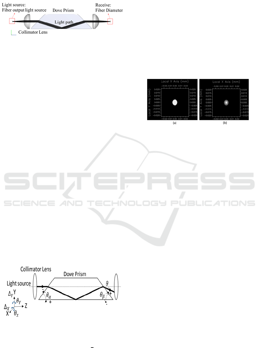
Figure 1: FORJ simulation model.
In the section 2, the FORJ simulation parameters
and light propagation mathematical formula were
introduced. In the section 3, the tolerance analysis
results were introduced. In the section 4, the
simulation results are discussed. In the section 5, the
conclusion was introduced.
2 FORJ MODEL
CONSTRUCTION
The FORJ tolerance analysis composed of output
position deviation of different wavelength, light
source position error, dove prism manufacture error,
light source tilt and decenter error. The tolerance
analysis was created by the optical simulation
software (FRED). The software simulated the
propagation of light through FORJ by raytracing. The
FORJ composed of fiber, collimation lens and dove
prism, as shown in Figure 1.
The light output through the collimating lens was
approximately parallel to the optical axis of the dove
prism. In the ideal dove model, the direction of light
propagation after the dove was the same as the input
light. In practice, the dove prism had manufacturing
errors, so the direction of the output light was different
from the direction of the input light, as shown in Figure
2. In the paper, the size of dove prism was 25 x 25 x
105.68
with the size tolerance of 0.13 Legs,
0.38 Hypotenuse. The angular tolerance of the dove
prism input and output interface was 2 armin [13].
Figure 2: Ray propagation in the dove prism.
The ray propagation output deviation formula:
θ
cos
sin
cos
(1)
Where
is the input surface of dove prism,
is the
exit surface of dove prism, n is the dove prism
reflection index.
In the optical simulation software, we built a
complete FORJ model. These simulated parameters
were collected from the actual optical components.
Through different dove prism manufacturing errors
and assembly errors, we could obtain different
efficiency, spot size and spot position on the receiver,
as shown in Figure 3. These data could use to create
the tolerance analysis.
Figure 3: Simulation irradiance map. (a) Fiber output light
source. (b) Through the FROJ output light source.
3 THE FORJ TOLERANCE
ANALYSIS
3.1 Output Spot Position of Different
Wavelength
The wavelengths commonly used for fiber-optic
communication signals were 850 nm, 1310 nm, and
1550 nm. The different wavelength had the different
reflection index in the same material. Therefore,
different wavelengths of light passing through the dove
prism had different spot positions, as shown in Figure
4. The short wavelengths had a higher reflectance
index in dove prism materials, so the positional
deviation was larger. The positional deviation between
850 nm and 1550 nm was approximately 400 μm.
Therefore, the position of receiver of FORJ could tune
from 0 to 400 μm, it could accommodate the three
different communication wavelengths.
3.2 Fiber Couple Tolerance Analysis
The FORJ coupling error consisted of dow prism
manufacturing errors, source tilt and decenter errors.
The light source generated beams of different
diameters through the collimating lens. The beams of
different diameters affected the FORJ tolerance
distribution. In this section, we used different
diameter beams to perform tolerance analysis in
PHOTOPTICS 2020 - 8th International Conference on Photonics, Optics and Laser Technology
72
different dove prism manufacturing errors, as shown
in Figure 5, 6 & 7.
Figure 4: The different manufactory errors of FORJ of
output spot position deviation with different wavelength.
(a)
(b)
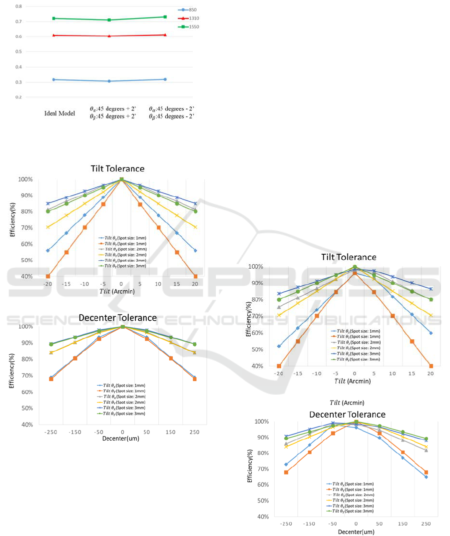
Figure 5: Different diameter beams tolerance analysis in the
ideal dove Prism. (a) Input light tilt tolerance analysis. (b)
Input light decenter tolerance analysis.
According to the tolerance simulation results, the
tolerance distribution of the small diameter beam was
more sensitive than the large diameter beam. When
the diameter of beam was 1mm and the light of tilt Y
tolerance was ±20 arcmin, the coupling efficiency
dropped to 40%. When the diameter of beam was
3mm and the light of tilt Y tolerance was ±20 arcmin,
the coupling efficiency was still over 80%. When the
decenter was within ±250 μm, the beam coupling
efficiency over 2 mm diameter exceeded 80%. In the
manufacturing error of different dove prisms, the
tolerance distribution changed, and the efficiency
difference was about 5%.
4 DISCUSSION
The spot positional deviation between 850 nm and
1550 nm was approximately 400 μm. The key factor
affecting the assembly tolerance distribution was the
beam diameter. The tolerance distribution of the tilt
Y felled faster than the tilt X. When the diameter of
beam was 1mm and the light of tilt Y tolerance was
±20 arcmin, the coupling efficiency dropped to 40%.
When the diameter of beam was 3 mm and the light
of tilt Y tolerance was ±20 arcmin, the coupling
efficiency was still over 80%. When the decenter was
within ±250 μm, the beam coupling efficiency over 2
mm diameter exceeded 80%. Therefore, in the
assembly tolerance, the tilt tolerance was more
sensitive than the decenter tolerance.
(a)
(b)
Figure 6: Different diameter beams tolerance analysis in the
manufacture error dove Prism. (:45 degrees - 2’,
:45
degrees - 2’) (a) Input light tilt tolerance analysis. (b) Input
light decenter tolerance analysis.
Optimization of Coupling Efficiency of Fiber Optic Rotary Joint by Ray Tracing
73
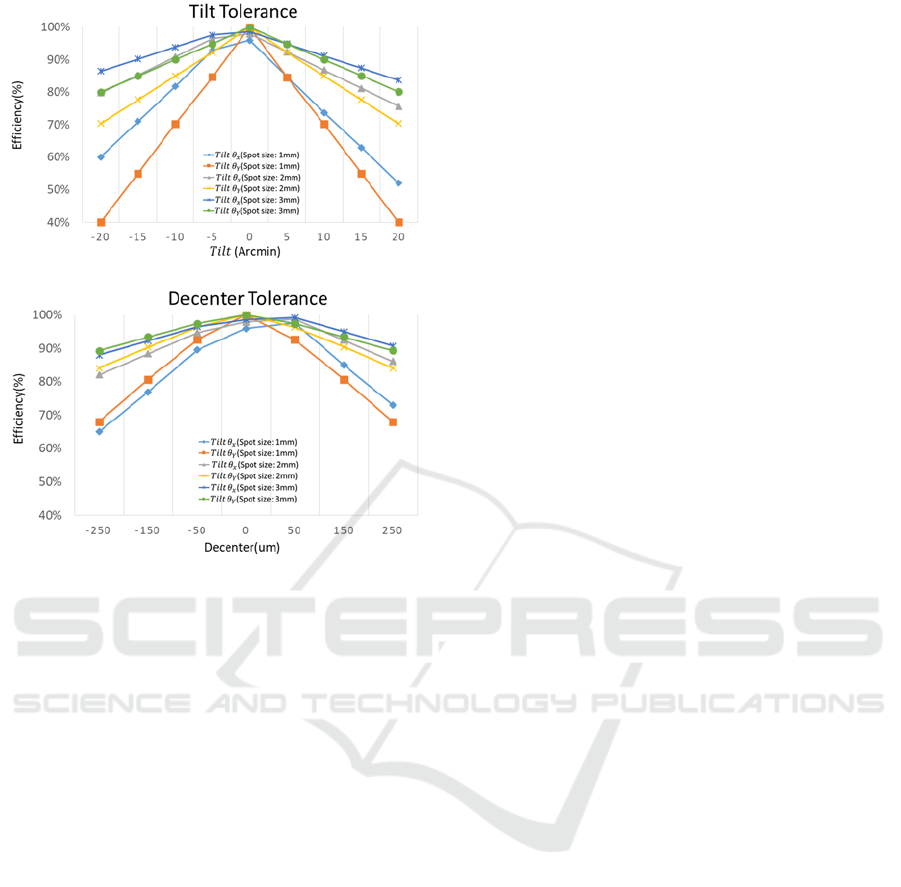
(a)
(b)
Figure 7: Different diameter beams tolerance analysis in the
manufacture error dove Prism. (
:45 degrees + 2’,
:45
degrees + 2’) (a) Input light tilt tolerance analysis. (b) Input
light decenter tolerance analysis.
At present, the optical component tilt error was
less than ±10 arc minutes, and the decenter error was
less than ±50 μm. Therefore, in the current assembly
tolerances, the suitable beam diameter was 2 mm. The
2 mm beam diameter of coupling efficiency was over
80% in the tilt error ±10 arcmin and decenter error
±250 μm. The 2 mm cross-sectional area was 44%
smaller than the 3 mm cross-sectional area. The FORJ
could arrange more fibers and transmit more signals
at the same time. If the FORJ want to accommodate
three different communication wavelengths, he
position of receiver of FORJ required tuning range
from 0 to 400 μm.
5 CONCLUSIONS
In the paper, a misalignment and field magnification
tolerance analysis for the coupling efficiency of FORJ
was presented. It helped producers easily define
element specifications and assembly tolerances for
FORJ. The 2 mm beam diameter was the most
suitable for current assembly tolerances. The
coupling efficiency exceeded 80% when the tilt error
was ±10 arcmin and the decenter error was ±250 μm.
If the FORJ want to accommodate three different
communication wavelengths, the position of receiver
of FORJ required tuning range from 0 to 400 μm. In
the future, we could create a FORJ system according
to the simulation parameters. The practice experiment
data would compare to our simulation results that
used to prove our simulation results.
ACKNOWLEDGEMENTS
The authors would like to express their appreciation
for financial aid from the Ministry of Science and
Technology, R.O.C under grant numbers MOST 108-
2221-E-492-019, MOST 108-2218-E-492-010 and
MOST 107-2622-E-492-017-CC3. The authors
would also like to express their gratitude to the
Taiwan Instrument Research Institute of National
Applied Research Laboratories for the support.
REFERENCES
Jia, D., Jing, W., Zhang, Y., Wang, G., Tang, F., & Zhang,
J. (2005). Bidirectional dynamic data transmission
through a rotary interface. Optical Engineering, 44(5),
050503.
Liu, J., Zhu, B., Jiang, H., & Gao, W. (2013). Image
analysis measurement of cottonseed coat fragments in
100% cotton woven fabric. Fibers and Polymers, 14(7),
1208-1214.
Jia, D. G., Jing, W. C., Zhang, Y. M., Zhou, G., Zhang, J.,
& Tang, F. (2005). Low-loss fiber optic rotary joint
using C-lens collimators. Optoelectronics Letters, 1(3),
221.
Shi, Y., Klafter, L., & Harstead, E. (1985). A dual-fiber
optical rotary joint. Journal of lightwave technology,
3(5), 999-1004.
Liu, L., & Chen, N. G. (2006). Double-pass rotary mirror
array for fast scanning optical delay line. Applied
optics, 45(21), 5426-5431.
Mathias Johansson, Sverker Hard. (1999). Design,
fabrication, and evaluation of a multi-channel
diffractive optic rotary joint,Applied Optics, 38(8):
1302-1310
Deng, Y. X., Zhou, G., & Liu, W. (2001). Dual-channel
fiber optic rotary joint of symmetrical optical system,
Journal of Optoelectronics·Laser, 12(8):792-794
Jia, D., Yu, C., Jing, W., Zhang, H., & Zhang, Y. (2008,
January). Effect of misalignment on rotating coupling
efficiency of the Dove prism. In Advanced Materials
and Devices for Sensing and Imaging III (Vol. 6829, p.
68290S). International Society for Optics and
Photonics.
PHOTOPTICS 2020 - 8th International Conference on Photonics, Optics and Laser Technology
74

Shapar, V. (2018). Principles of compensation of optical
rays’ rotation and multi-channel optical rotary
connectors. Applied optics, 57(27), 8023-8033.
Gutierrez-Herrera, E., & Strojnik, M. (2008).
Interferometric tolerance determination for a Dove
prism using exact ray trace. Optics Communications,
281(5), 897-905.
Optimization of Coupling Efficiency of Fiber Optic Rotary Joint by Ray Tracing
75
