
Stress Analysis of a Circular and Pinion Gear on Sea Wave
Power Plant Design in Bangka Island
Firlya Rosa, R. Priyoko Prayitnoadi
and Aljun Yusuf Gunawan
Department of Mechanical Engineering, Faculty of Engineering, Universitas Bangka Belitung, Bangka, Indonesia
Keywords: Stress analysis, sea wave power plant design, circular gear, pinion gear
Abstract: Based on data for a maximum wave height of 1.22 m on the Bonded Beach, Bangka Tengah Regency,
Bangka Belitung Islands Province, Indonesia, in January 2019, the alternative wave power plants was
designed using circular and pinion gear transmission elements as rotation elements. The wave motion moves
the buoy, and then the down and up motion is converted into a rotary motion which rotates the generator
drive shaft. This study aims to determine the circular and pinion gears' strength in receiving the waves'
forces. This research conducted static analysis software using the von mises and safety factor method on
circular and pinion gear. From the calculation of the wave force and buoyancy force, the maximum force
received by the circular gear is 689.54 N. material of 350 MPa with a minimum safety factor of 1.03 lower
than the permitted safety factor so that circular and pinion gear cannot accept the force exerted by the
waves.
1 INTRODUCTION
One of the abundant new and renewable energy
sources in Indonesia, especially the Bangka Belitung
Islands Province with many coastal areas, is the sea.
Ocean energy that can be utilized to date consists of
sea waves and sea wind. Sea wind could use as an
energy source using wind turbines, while ocean
waves can be utilized using Wave Energy
Converters (WEC) technology which is not harmful
to the environment (Drew, et al., 2009).
The use of WEC is influenced by location with a
wave period of 2-25 s (Neill, Hashemi, 2018). The
buoy is one of the Wave Energy Converters that can
be used according to sea conditions and increase
energy extraction efficiency (Kim, et al., 2015). For
the Bangka Belitung Islands Province, the wave
height ranges from 0.1-1.25 m with a period of 1.12
- 3.97 s in December 2018 - April 2019 (Kim, et al.,
2015).
Several mechanisms of the WEC tool that are
being developed are by utilizing the float moves up
and down and then converted into linear force and
motion using a link that is connected by a
mechanization system using a rack and pinion gear
or a system using circular and pinion gear
mechanization as shown in Figure 1 (Priyanka, et al.,
2019). The selected pinion gears use the involute
system because these involute gears are widely used
in the industry. In the process of making this type of
gear produced by the hob cutter on the hobbing
machine has a higher efficiency than other types of
gears (Bair, 2004).
(a)
(a)
(b)
Figure 1. Sea wave power plant design using :
(a) rack and pinion gear
(Priyanka, et al., 2019),
(Rosa, Prayitnoadi, 2020)
(b) circular and pinion gear
(Priyanka, et al., 2019)
Rosa, F., Prayitnoadi, R. and Gunawan, A.
Stress Analysis of a Circular and Pinion Gear on Sea Wave Power Plant Design in Bangka Island.
DOI: 10.5220/0010798800003317
In Proceedings of the 2nd International Conference on Science, Technology, and Environment (ICoSTE 2020) - Green Technology and Science to Face a New Century, pages 157-160
ISBN: 978-989-758-545-6
Copyright
c
2022 by SCITEPRESS – Science and Technology Publications, Lda. All rights reserved
157
From the motion simulation results, at a
maximum wave height of 1.22 m, it was found that
the rotation obtained on the shaft sea wave power
plant using rack and pinion gear was 3.47 rpm and
on the sea wave power plant shaft using circular and
pinion gear was 29.16 rpm (Priyanka, et al., 2019).
Meanwhile, for the static analysis, the strength of
the von mises sea wave power plant using rack and
pinion gear is 53.14 MPa, smaller than the yield
strength of the material with the safety factor that
occurs a minimum of 6.59 (Rosa, Prayitnoadi,
2020). By using the same buoy size as the sea wave
power plant using rack and pinion of 200x700x1050
mm and ignoring the weight of the buoys with
geometry and links made of carbon steel with
dimensions 100 x 2500 mm (Rosa, Prayitnoadi,
2020), it is necessary to carry out a static analysis on
the sea wave power transmission element. Plant
using circular and pinion gear.
2 RESEARCH METHODS
2.1 Specification of Circular and Pinion
Gear
To transmit the wave force and motion into straight
motion and rotational motion, this study uses
circular and gear pinion transmission elements with
specifications as in Table 1 and the geometry and
dimension of the circular and pinion gear as shown
in figure 2 and figure 3.
Table 1. Dimension parameters considered on a circular
gear
Parameters Notations Values
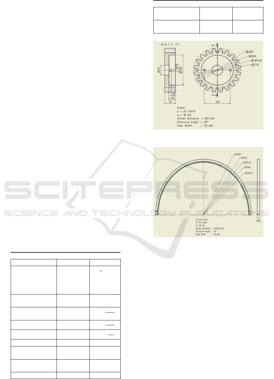
Modul M 10 m
m
System of gear
teeth
-
14
Full-
depth
involute
s
y
stem
Material - Steel,
carbon
Ultimate tensile
strength
iz
420
Yield strength
y
350
Mass density
7850
Pressure angle
20
The diameter of
the circular
g
ea
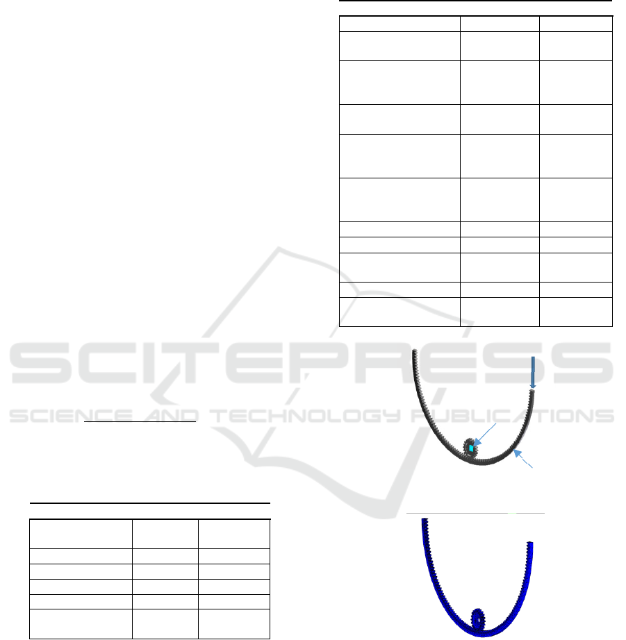
r
Dp 1900 mm
Number of the
circular
g
ear teeth
T
P
95 teethes
The
p
itch D
p
200 m
m
Parameters Notations Values
diameter of the
p
inion
Number of pinion
teeth
T
P
20 teethes
Figure 2. Geometry and dimension of the pinion gear
Figure 3. Geometry and dimension of the circular gear
2.2 Parameter Considered
2.2.1 Sea Wave Data
Sea wave is influenced by a wave crest, wave
trough, wavelength (L or ), wave height (H), wave
period (T) (Susanto, 2015). Wave height data was
measured in January 2019, which was obtained from
the Meteorology, Climatology and Geophysics
Agency (BMKG) with the Bonded coastal location,
Central Bangka Regency, Bangka Belitung Islands
Province (Priyanka, et al., 2019), (Rosa, Prayitnoadi,
2020).
2.2.2 Power Wave & Wave Force
Power wave (P
-wave
) has resulted from the density of
seawater (=1030 kg/m
3
), gravity (g), wave height
ICoSTE 2020 - the International Conference on Science, Technology, and Environment (ICoSTE)
158
(H) dan wave period (T). While the wave force
(F
wave
) generated from a wave depends on the wave
power (P
-wave
), wavelength () dan wave period (T)
(Yusnitasari, Hendrowati, 2012).
2.2.3 Force on the Float
The force generated by the buoy consists of the
maximum wave force. The buoyancy force is
influenced by the density of seawater (), gravity (g)
and the volume of the float submerged in water (V)
(Yusnitasari, Hendrowati, 2012) (Journee, Massie,
2001), assuming the volume of the float is
submerged at 0.5 buoy height (Rosa, Prayitnoadi,
2020).
2.2.4 Buoy Force
The total force on the buoy is influenced by the wave
force, buoyancy force and buoyancy gravity.
F
𝐹
F
∇
𝐹
2.2.5 Force on Circular Gear
The force that occurs on the link is treated the same
as the analysis on the rack and pinion gear, assuming
a force with a link angle condition of 35 to sea level
with the calculation of the forces on the link as
follows (Prayitnoadi, et al., 2019):
F
.
.
.
Table 2. The force that occurs at the maximum wave
height on the Bonded coast of Central Bangka Regency,
Bangka Belitung Islands Province.
Parameters Notations Values
Maximum height
of sea wave
Max
1,22 m
Wave force F
ave
287.19 N
Buoyancy force
F
∇
689.54 N
Massa (assumed) F
massa
0 N
Forces on buo
y
F
generated
976.73 N
Normal force on
a circular gea
r
F
n
4906.06 N
3 RESULTS AND DISCUSSION
3.1 Modelling
The analysis uses Autodesk Inventor Version 2019
software with a static analysis using parameters as in
table 3 and constraints and mesh of the transmission
as shown in Figure 4 and Figure 5.
Table 3. Parameters considered of stress analysis
Parameters Notations Values
Su
pp
ort on
p
in A -
Detect and Eliminate
Rigid Body Modes
- Yes
Separate Stresses
Across Contact
Surfaces
-
Yes
Motion loads
analysis
- No
Avg. Element Size
(fraction of model
diameter
)
-
0.1
Min. Element Size
(fraction of avg.
size
)
-
0.2
Gradin
g
Facto
r
- 1.5
Max. turn angle -
60
Axial force on
circular
g
ea
r
W
a
=F
generated
4906.06
N=4.91 kN
Pin constraint A -
Frictionless
constraint
B -
Figure 4. Modelling, load and constraints
Figure 5. Mesh model
3.2 Static Analysis of Circular and
Pinion Gear
3.2.1 Von Mises
The stress on teeth gears is compared to the
allowable stress on the material based on yield
B
W
A
Stress Analysis of a Circular and Pinion Gear on Sea Wave Power Plant Design in Bangka Island
159

strength. The static stress analysis uses the Von
Mises Stress method due to the material of gear is
ductile (Khurmi, Gupta, 2005). Figure 6 shows that
the maximum stress occurs at 339.5 MPa in a teeth’s
pinion gear and the minimum stress occurs at 0 MPa
in a circular gear. From this analysis, the stress on
pinion gear is smaller than the material yield
strength. It means that the pinion gear strength able
to withstand the force that occurs.
Figure 6. Von mises stress analysis
3.2.2 Safety Factor
For safety purposes, the rotating shaft's safety factor
must be more than 1.5 (Suryavanshi, et al., 2017).
From the analysis, the minimum safety factor on
pinion gear is 1.03, while the maximum safety factor
on circular gear is 15. The safety factor on pinion
gear is not satisfying, while the safety factor on
circular gear fulfils the safety factor.
Figure 7. Safety factor analysis
4 CONCLUSION
The analysis using Autodesk Inventor 2019 software
found that the von mises at carbon steel pinion gear
with a yield strength of 350 MPa were able to
withstand force from sea wave and buoyance force
on the Bangka Belitung sea. The minimum safety
factor of pinion gear was lower than the safety factor
requirement.
ACKNOWLEDGEMENTS
We gratefully acknowledge the funding from
Universitas Bangka Belitung through the "Penelitian
Dosen Tingkat Jurusan" to publish this paper.
REFERENCES
Bair B W, 2004, Computer-aided Design of Elliptical
Gears with Circular-arc Teeth, Mechanism and
Machine Theory, Vol. 39, No. 2, pp. 153–68
Drew B, Plummer A R, Sahinkaya M N, 2009, A Review
of Wave Energy Converter Technology, Proceedings
of the Institution of Mechanical Engineers, Part A:
Journal of Power and Energy Vol. 223, pp. 887–902
Journee J, Massie W, 2001, Offshore Hydromechanics (1
st
edition), Delft University of Technology, Delft.
Khurmi R S, Gupta J K, 2005, A Textbook of Machine
Design (S.I. Units), Eurasia Publishing House, New
Delhi.
Kim J, Kweon HM, Jeong W M, Cho I H and Cho H Y,
2015, Design Of The Dual-Buoy Wave Energy
Converter Based On Actual Wave Data Of East Sea,
International Journal of Naval Architecture and
Ocean Engineering, Vol. 7, No. 4, pp. 739-749.
Neill S P, Hashemi M R, 2018, Fundamentals of Ocean
Renewable Energy: Generating Electricity from the
Sea, Academic Press, Cambridge.
Priyanka Prayitnoadi R, Rosa F, Hudatwi M, Ubed
Nurhadi M, Febrianto A, Roliana N, 2019 Analysis of
Sea Wave Power Plant Design in Bangka Island
Indonesia, IOP Conference Series: Materials Science
and Engineering.
Rosa F, Prayitnoadi R P, 2020, Stress Analysis of a Rack
Gear on Sea Wave Power Plant Design in Bangka
Island, International Conference on Green Energy and
Environment 2020.
Suryavanshi O D, Prasad Sathe P, Takey M A, 2017,
Designing Of The Rack And Pinion Gearbox For All-
Terrain Vehicle For The Competition Baja Sae India
And Enduro Student India, International Journal of
Research in Engineering and Technology, Vol. 06, pp.
79–84.
Susanto I M, 2015, Studi Karakteristik Energi Listrik Yang
Dihasilkan Pembangkit Listrik Tenaga Gelombang
Laut ( Pltgl ) Metode Pelampung Dengan Variasi
Dimensi Pelampung dan Panjang Lengan, Institut
Teknologi Sepuluh Nopember, Surabaya.
Yusnitasari Y, Hendrowati W, 2012, Studi Eksperimen
dan Analisa Energi Listrik yang Dihasilkan
Mekanisme PLTGL Metode Pelampung Apung
dengan Variasi Pembebanan dan Panjang Lengan,
Jurnal Teknik POMITS, Vol. 1, No. 2, p. 1-6.
ICoSTE 2020 - the International Conference on Science, Technology, and Environment (ICoSTE)
160
