
The Optimized Geometry Solar Chimney as Passive Cooling Solution
for Buildings in Jakarta
Dalhar Susanto and M. Aryo Wicaksono
Department of Architecture, Faculty of Engineering, Universitas Indonesia, Kampus UI Street, Kukusan, Depok, Indonesia
Keywords: Geometry solar-chimney, Passive-cooling, Ventilation.
Abstract: Solar chimney uses solar radiation to trigger the buoyancy-driven flow in the building to allow saturated air
inside the building to flow out of the building. At this stage, this research aims to find the optimized geometry
for the solar chimney that can be used in Jakarta and display the performance of the optimized solar chimney
as one of the solutions for passive cooling. In the present paper, the numerical method investigates the airflow,
temperature distribution, and thermal comfort inside the empty room without any human and mechanical
activity connected with an inclined solar chimney. RNG k-epsilon modeled the steady-state 3D computational
fluid dynamics (CFD) to investigate flow inside the chimney. Discrete ordinate (DO) non-grey radiation
model with solar ray tracing is used to simulate heat transfer in the chimney from each time in Jakarta.
Chimney geometry parameters were monitored from inclination angle, width, air gap, chimney length,
airflow, and average outlet velocity. This research's result is that the optimized solar chimney's optimized
geometry is suitable for Jakarta climate and the optimized solar chimney's performance as passive cooling in
Jakarta.
1 INTRODUCTION
Air conditioning or ventilation purposes use the
most energy demand in a building. Space
cooling dominates half of the energy demand in
commercial buildings, followed by lighting,
cooking, and water heating. Nowadays, people
tend to use mechanical air conditioning or
ventilation to achieve thermal comfort in the
building. Mostly, non-renewable energy is used
to generate electricity to power this mechanical
ventilation.
Solar chimney uses solar radiation to trigger the
buoyancy-driven flow in the building to allow
saturated air inside the building to flow out of the
building. At this stage, this research aims to find the
optimized geometry for the solar chimney that can be
used in Jakarta and display the performance of the
optimized solar chimney as one of the solutions for
passive cooling. In the present paper, the numerical
method investigates the airflow, temperature
distribution, and thermal comfort inside the empty
room without any human and mechanical activity
connected with an inclined solar chimney. In this
research, ANSYS FLUENT 2020 R2 Academic was
employed to develop a three-dimensional numerical
model for this research.
2 RESULTS AND DISCUSSION
2.1 Model
The model is based on research that was done by
abdeen et al (Abdeen, et al., 2019). A wooden
chamber with 3 m x 3 m x 3 m connected to the
chimney on the ceiling and the absorber facing the
north, opening measured 0,6 m x 0,6 m on the south
side of the room. For the simulation's initial stage, the
chimney is measured with 1,4 m lengths, inclined to
45
o
, 0,6 m width, 0,25 m air gap—this model is
located in jakarta with coordinate 6.21462
o
s,
106.84513
o
e. The chimney's geometry, such as
length, inclination angle, width, and air gap, will be
varied at the later stage of this simulation using the
design exploration feature in ansys.
Susanto, D. and Wicaksono, M.
The Optimized Geometry Solar Chimney as Passive Cooling Solution for Buildings in Jakarta.
DOI: 10.5220/0010792200003317
In Proceedings of the 2nd International Conference on Science, Technology, and Environment (ICoSTE 2020) - Green Technology and Science to Face a New Century, pages 53-57
ISBN: 978-989-758-545-6
Copyright
c
2022 by SCITEPRESS – Science and Technology Publications, Lda. All rights reserved
53
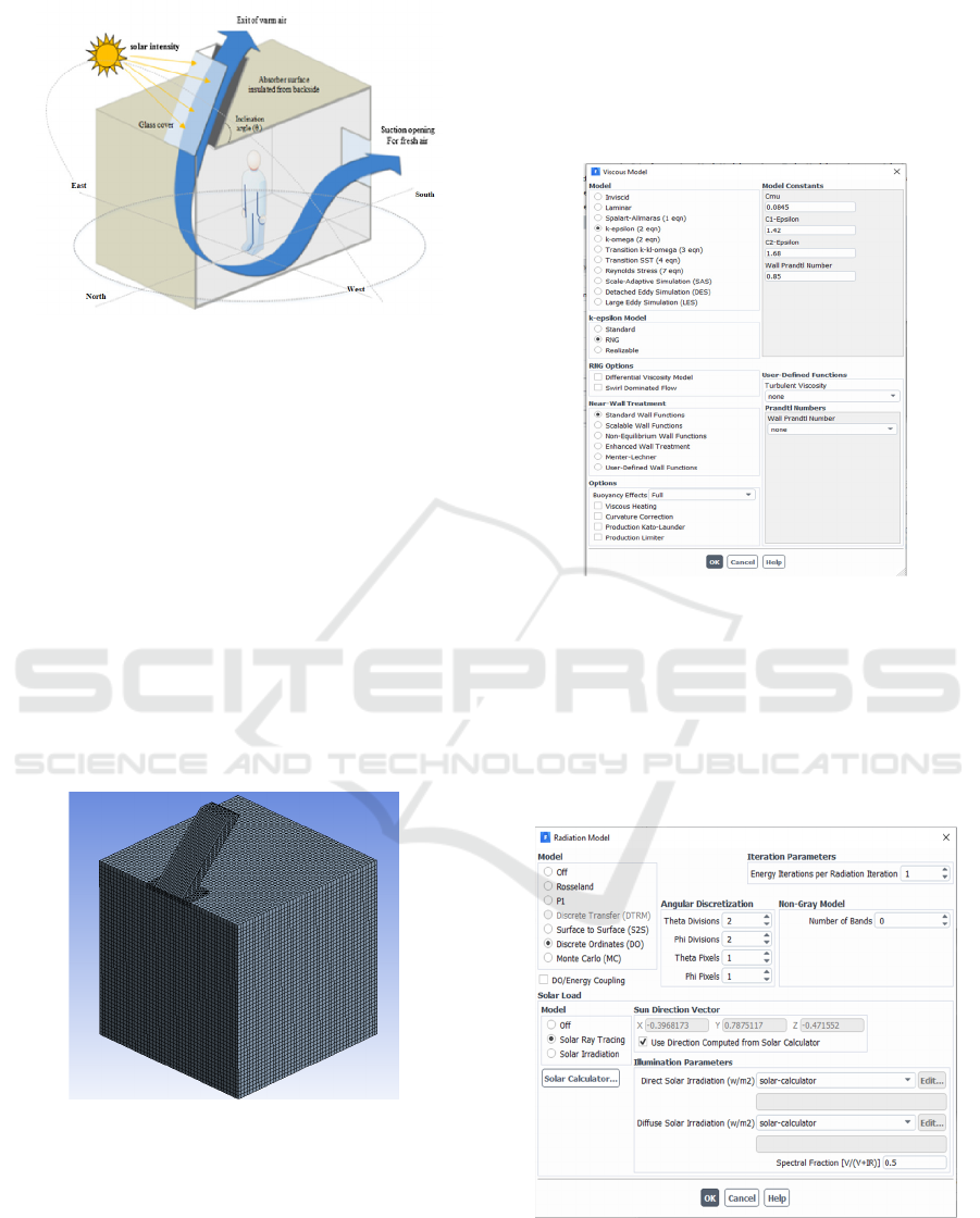
Figure 1. Ventilation flow diagram of the model
The chimney itself is made of 4 mm clear glass on the
north, 4 mm opaque glass on the west and east side of
the chimney, 1 mm steel sheet on the south side of the
chimney act as absorber, and 50 mm insulation glass
wool on the backside of the absorber to prevent heat
loss from the absorber.
2.2 Mesh
The hexahedral mesh was implemented in this model,
with a total of mesh 112.175 elements. If the mesh
number is lower than the current total mesh, the
simulation will fail in some chimney variation models
using the Design Exploration feature. If more
extensive, the simulation's runtime will be longer, but
the results will be more accurate.
Figure 2. The meshing of the model
2.3 Computational Fluid Dynamics
Configuration
Three-dimensional, fully turbulent, and
incompressible flow is conducted with ANSYS
FLUENT. The energy model is set to activate to
simulate the heat transfer of the chimney. The
renormalization group (RNG) k-ε model is
implemented to simulate chimney flow. This model
is the most accurate in flow separation, streamline
curvature, and flow stagnation (Chen, 1995).
Gravitation at Y-axis is set to 9,8 m/s2. The buoyancy
effect is activated. For wall setting, the standard
treatment is implemented for this simulation.
Figure 3. Model setup for flow
The discrete ordinate (DO) model is implemented to
simulate the solar load model's radiation to the
chimney. The setup for the solar load model in this
simulation is placed in Jakarta. The solar load model
is set to 11:00 on 1 August because between June to
August is when demand for ventilation is high in a
year.
Figure 4. Model setup for radiation
ICoSTE 2020 - the International Conference on Science, Technology, and Environment (ICoSTE)
54
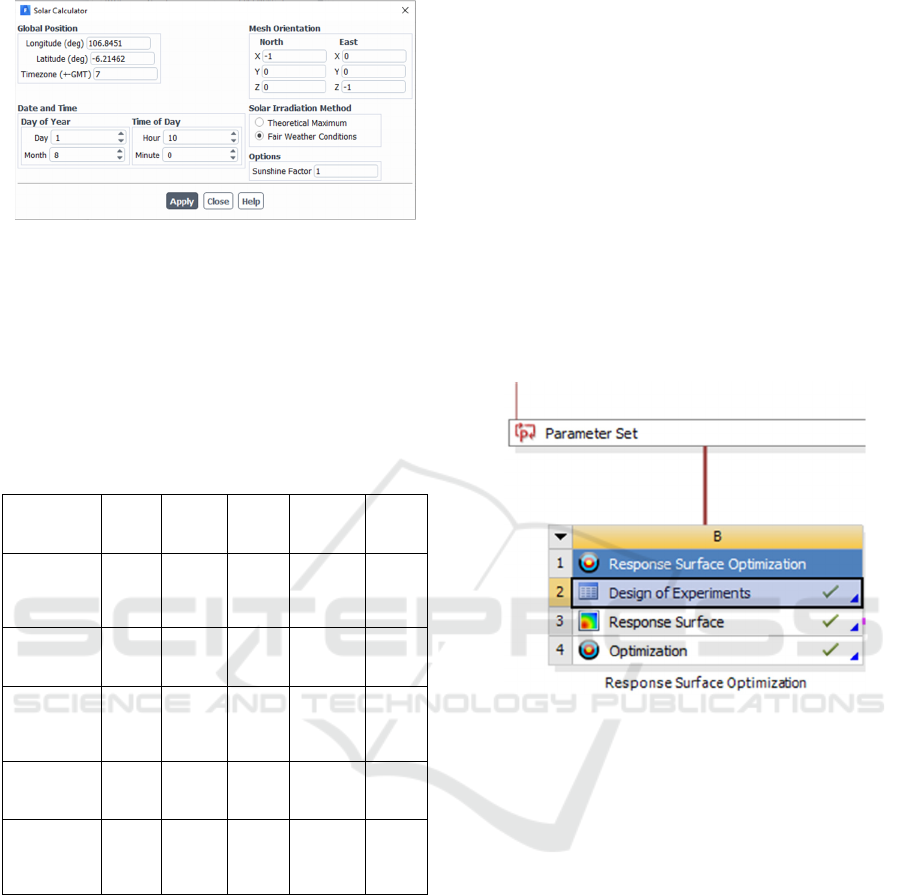
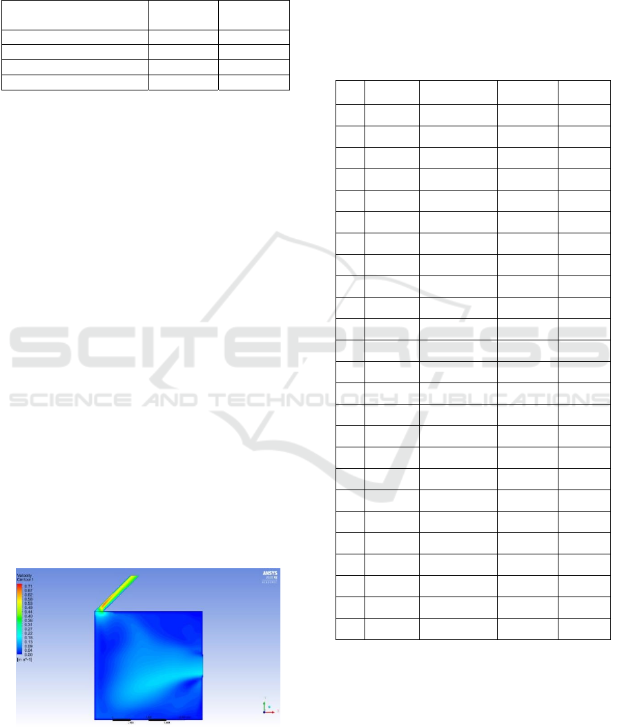
Figure 5. Solar calculator setup
Thermo-physical for fluid properties is assumed
to be constant except density. Density is modeled by
the Boussinesq approximation, which delivers faster
convergence than models that vary density as a
function of temperature (ANSYS Fluent. co, 2015).
Thermo-physical properties for other materials, such
as glass, steel, wood, and insulation, based on Table
Table 1. Material setup for model
Properties Air Glass Steel Wood
Insu
lation
Density
(kg/m
3
)
Bous
sines
q =
1,18
2220 8030 700 10
C
p
(Specific
Heat)
(J/(kg K))
1006.
43
830
502,4
8
2310 830
Thermal
Conductivit
y (W/(m
K))
0,024
2
1,15 16,27 0,173 0,1
Viscosity
(kg/(m s))
1,789
4*10
−
5
- - - -
Thermal
Expansion
Coefficient
(1/K)
0,003
35
- - - -
The Semi-Implicit Method for Pressure-Linked
Equations (SIMPLE) algorithm was applied as
pressure-velocity coupling. The least-square cell-
based method is applied as a gradient discretization.
The staggering pressure option (PRESTO!) method is
applied as pressure discretization. The second-order
upwind method is applied for momentum, turbulent
kinetic energy, turbulent dissipation rate, energy, and
discrete ordinates discretization. Absolute
convergence is achieved when residuals were less
than 10
-4
.
For boundary conditions, a no-slip condition is
applied for every wall in the model. Mixed thermal
conditions were applied for all heated surfaces. The
ambient temperature and pressure were assumed to be
35
o
C and 1 atm. A pressure inlet with zero-gauge
pressure is set as a room inlet with incoming air
assumed to be equal to ambient temperature. A
pressure outlet with zero-gauge pressure is set to be a
room outlet assumed to be equal to the ambient
pressure.
2.4 Design Optimization
Chimney geometry, such as length, inclination angle,
width, and air gap, will be varied until the outlet
achieves optimized airflow and velocity. Using CFD
to simulate each variable will be a long process. To
shorten the process for each variation and optimize
the output, ANSYS 2020 R2 Design Exploration is
employed.
Figure 6. Design Exploration steps in ANSYS
The process for optimization encompasses the
initial sampling step through Design of Experiments
(DOEs), followed by interpolation technique using
Response Surface Method (RSM) and optimization
using the Multi-Objective Genetic Algorithm
(MOGA).
2.4.1 Design of Experiments (DOEs)
The large number of tests required for one-by-one
parameter variation will be time-consuming and not
efficient. Although this step is also time-consuming,
this process is more efficient than many tests. DOEs
is a statistical approach that explores interactions
between design and output variables through
minimum sampling points, which is set to 25
sampling points in this research. Angle, width,
inclination angle, and air gap are stated as input
parameters, then airflow and average velocity at the
outlet as the output parameter. The optimal Space
Filling Design (OSFD) technique is selected because
of its ability to provide large amounts of information
The Optimized Geometry Solar Chimney as Passive Cooling Solution for Buildings in Jakarta
55
with a minimum number of numerical simulations
(Abdeen et al., 2019) [1].
Table 2. The minimum and maximum value of each input
parameters
Input Parameter
Minimum
Value
Maximum
Value
Inclination Angle (
o
) 25 75
Len
g
th
(
m
)
1,5 2,5
Width
(
m
)
0,5 3
Air Ga
p
(
m
)
0,1 0,3
2.4.2 Response Surface Method (RSM)
Response Surface Method (RSM) is a selected
approximation function that produces a correlation
between input and output parameters used by the
fitting algorithm indicated in DOEs methodology.
RSM is obtained using a second-order polynomial
regression model set and the results generated from
DOEs.
2.4.3 Optimization
After RSM is produced, optimization can be
performed using MOGA to derive the optimal design
based on the targets sets by maximizing the mass flow
rate and average air velocity on the outlet. MOGA is
an evolutionary algorithm with several objective
functions optimized simultaneously and subject to
inequality and equality constraints (ANSYS Fluent.
co, 2015) [3].
2.5 Simulation Results
The model based on the initial design generates
airflow 0,043 m
3
/s and average velocity on the output
0,405 m/s, as displayed in Figure 7. This simulation
shows air on the lower height of the chimney reaches
the maximum velocity value, and the velocity was
slower near absorber than near glass.
Figure 7. Velocity distribution on initial model design
2.5.1 Design of Experiments Results
DOEs method generates 25 design points and results
of the output parameters based on the setup from
Table 2. These design points showed in Table 3, and
the results were fed to RSM as data for the
interpolation approach to produces reasonably
accurate predictions.
Table 3. Design points generated from DOEs method
No.
Width
(m)
Inclination
Angle (
o
)
Air Gap
(m)
Length
(m)
1
1,05
44 0,104 1,88
2
2,55
58 0,112 1,92
3
0,85
54 0,224 1,56
4
1,45
72 0,272 1,96
5
1,25
60 0,12 2,32
6
2,65
56 0,152 2,4
7
1,75
66 0,24 2,44
8
2,95
42 0,184 1,72
9
0,65
36 0,176 2,16
10
2,05
46 0,296 2,24
11
2,25
30 0,128 2
12
0,55
64 0,2 2,08
13
1,15
70 0,136 1,76
14
2,45
32 0,264 1,8
15
2,15
74 0,168 2,12
16
0,95
38 0,28 1,84
17
1,65
40 0,16 2,48
18
1,85
48 0,144 1,52
19
1,35
28 0,192 1,68
20
1,95
52 0,288 1,64
21
2,75
34 0,216 2,28
22
2,35
68 0,208 1,6
23
2,85
62 0,248 2,04
24
0,75
50 0,256 2,36
25
1,55
26 0,232 2,2
2.5.2 Response Surface Method Results
From data generated in the DOEs method displayed
in Table 3. Each input and output parameter
correlation can be explored and
displayed in a
three-dimensional response chart, as showed in
Figure 8.
ICoSTE 2020 - the International Conference on Science, Technology, and Environment (ICoSTE)
56
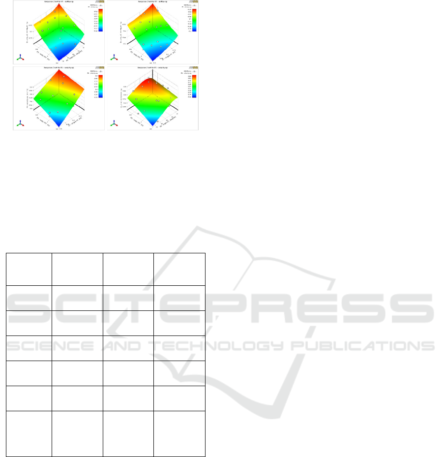
Figure 8. Response charts for airflow and velocity
2.5.3 Optimization Results
Three candidates from the optimization method used
MOGA by generating 10.000 designs to explore the
optimal solar chimney design by maximizing airflow
and average outlet velocity.
Table 4. Optimization candidates
Parameters Candidate 1 Candidate 2 Candidate 3
Width (m) 2,9986 2,986 2,9988
Inclination
Angle (
o
)
51,901 50,762 49,281
Air Gap
(m)
0,10228 0,10064 0,10151
Length
(m)
2,4966 2,4975 2,4934
Airflow
(m
3
/s)
0,15952 0,15607 0,15488
Average
Velocity
on The
Outlet
(m/s)
0,61919 0,62593 0,62823
From the three candidates generated from MOGA,
there is a slight difference. Candidate 2 is chosen as
the best design because it maximizes airflow and
average outlet velocity.
3 CONCLUSIONS
In this research, a three-dimensional steady CFD
model was developed. Using the ANSYS® 2020 R2
FLUENT Design Exploration, an optimization
technique was used to increase the air velocity and
airflow from buoyancy effects inside the space. This
optimization method can integrate various chimney
parameters, including the height, width, inclination
angle, and air gap between the glass and the absorbing
wall. The optimal solar chimney is derived from the
optimization method, which features 51
o
inclination
angle, width 2,9988 m, air gap 0,1 m, chimney length
2,5 m. The finding highlights the potential and
advantages of employing this 3D optimization
technique to enhance natural ventilation solutions for
Jakarta buildings by passive solar chimneys.
REFERENCES
Abdeen, A, Serageldin, A, Ibrahim, M, El-Zafarany, A,
Ookawara, S, & Murata, R, (2019), Solar chimney
optimization for enhancing thermal comfort in Egypt:
An experimental and numerical study, Solar Energy,
524-536.
Chen, Q, (1995), Comparison of different k-ε models for
indoor air flow computations, Numerical Heat
Transfer, Part B: Fundamentals, 353-369.
ANSYS Fluent, co, (2015), ANSYS FLUENT Theory Guide
[WWW Document], Retrieved from
http://www,ansys,com/Products/Fluids/ANSYS-
Fluent.
The Optimized Geometry Solar Chimney as Passive Cooling Solution for Buildings in Jakarta
57
