
Infrastructure for an Integrated Industry 4.0
Life Cycle Spanning Design and Production Platform
Robert M
¨
uhlbacher
1,2
, Hans G
¨
opfrich
1
and Andr
`
as G
`
alffy
2
1
Institute of Information Systems and New Media, WU, Vienna University of Economics and Business, Austria
2
Turbulence Solutions GesmbH, Vienna, Austria
Keywords:
Industry 4.0, Reference Implementation, Integrated Production.
Abstract:
This paper proposes an infrastructure for the digitalisation and integration of tasks along the life cycle of
a lotsize-1 product from specification to depollution. The proposal shows the integration of existing open
source tools into a design and production infrastructure. Starting from the positioning of the approach within
the RAMI 4.0 framework, additional abstraction layers are presented, which help to organize the life cycle
process. Besides the layer conception a showcase implementation is presented, which provides a factory for
the production of model airplanes. The prototype shows the life cycle of a product instance as it is specified
down to the production and even further. The digital twin convoys the instance along its whole existence.
1 INTRODUCTION
The disruptive change in production technology has
been discussed in detail in the past years and has been
formulated in the term ”Industry 4.0” (Bundesmin-
isterium f
¨
ur Bildung und Forschung, 2013) in 2013.
The term subsumes a variety of technological and or-
ganizational components. The RAMI 4.0 framework
(Plattform 4.0, 2016) presented by the standardization
group of the German ”Plattform Industrie 4.0” work-
ing group in 2016 provides a multidimensional frame-
work. The framework proposes to locate activities
and objects dealt with in an Industry 4.0 project into
a description matrix consisting of these dimensions
”Layer”, ”Life Cycle” and ”Hierarchy”. ”Layer” in-
dicates the abstraction of the product itself from busi-
ness to asset, ”Life Cycle” describes the life cycle of
the product from design to production and mainte-
nance and ”Hierarchy” represents the organizational
and physical distribution of the production.
Based on these facts two thematic questions arise:
(a) How should existing technologies be integrated
into the framework? (b) Which building blocks are
needed to be implemented into a framework in order
to cover all phases from design to production? As
of the first, pilot factories were established to show
special aspects of existing methods in depth (Selim,
2019), (TU Graz, 2020) or (FH Vorarlberg, 2020) and
platforms were described (F. Belkadi et al., ). With
respect to the second field this paper presents abstract
building blocks of an Industry 4.0 factory formulated
in abstraction layers. A business domain in com-
paratively limited technical depth is described, but
throughout the complete life cycle. The presented ap-
proach contributes to the business, functional and in-
formation layer and the life cycle stream of the RAMI
4.0 Reference Model (Schweichhart, 2016). The hi-
erarchy dimension is not covered in this paper. It is
assumed not having a distributed structure although
distribution is kept in mind. A light weighted imple-
mentation of a digital twin architecture is prepared.
Unlike the approaches as i.e. (Fraunhofer Austria Re-
search, 2018) but more in the direction described in
(Gesellschaft f
¨
ur Informatik, 2017) the digital twin
is separated into the customer exposed properties and
the structure calculation function.
This paper is intended to give a fundamental
overview. Starting with the of the methodical com-
ponents, the paper describes the proposed abstraction
layers and finally presents business functions which
build the production process. A detailed description
of the single components will go beyond the scope of
this paper.
2 METHODICAL APPROACH
Methodically two different but interconnected proce-
dures have been chosen to coin out the presented the-
Mühlbacher, R., Göpfrich, H. and Gàlffy, A.
Infrastructure for an Integrated Industry 4.0 Life Cycle Spanning Design and Production Platform.
DOI: 10.5220/0010055400690075
In Proceedings of the International Conference on Innovative Intelligent Industrial Production and Logistics (IN4PL 2020), pages 69-75
ISBN: 978-989-758-476-3
Copyright
c
2020 by SCITEPRESS – Science and Technology Publications, Lda. All rights reserved
69
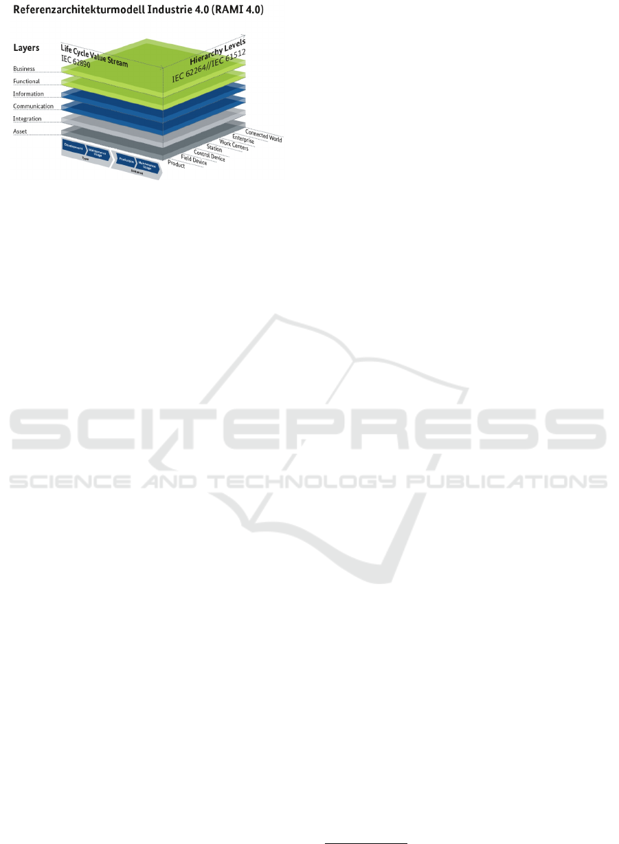
Figure 1: The RAMI 4.0 Reference Model (Schweichhart,
2016).
sis. On the one hand the RAMI framework is refined
by adding new specializations (top down procedure).
On the other hand a show case factory was developed.
This helped to find additional phenomena by intro-
spection of the development work.
2.1 The Model
RAMI 4.0 is the foundation of the described model.
RAMI proposes a multidimensional view: Layers,
Life Cycle, Hierarchy (Fig. 1).
The refinement of the business, functions and in-
formation layer is achieved in the model abstrac-
tion. The clarification of the life cycle dimension
is achieved by the description of business functions.
The hierarchy dimension is left untouched for the mo-
ment. It is assumed that one single ”company” sup-
ports the whole life cycle.
2.2 Business Domain
To show an end-to-end life cycle in an appropriate
amount of time it requires the selection of a suitable
business domain. A model airplane production was
chosen since it shows the studied phenomena in suf-
ficient complexity. The Industry 4.0 production pro-
cess of real airplanes, cars or other highly complex
structures would make it more complicated to find us-
able abstractions, as technical detail problems would
stand in the front. On the other hand, investigating
the production of a key ring pendant would eliminate
most of the interesting phenomena. For key ring pen-
dants the only customizable item is probably the text
written on it, whereas model airplanes are used in a
far more sophisticated operating environment (the air)
and have to show an expected behavior, namely to fly
better than the ballistic curve. Especially for the sim-
ulation it is important that the operating environment
is well understood and stable in the universe of dis-
course. It is conceivable to describe insurance con-
tracts in an Industry 4.0 manner, but their business
domain has a very specific and localized operating
environment, special risks, special legal regulations
which differ from country to country. The environ-
ment of the model airplanes (aerodynamics) is stable,
the lift can be calculated all over the world the same
way by
L = Cl ∗ ρ/2 ∗V
2
∗ S (1)
L = Lift in N, Cl = Lift coefficient dimensionless,
ρ = air density in kg/m
3
, V = velocity in m/s, S = span
in m.
2.3 The Factory
In parallel to the theoretical deduction a show case In-
dustry 4.0 factory for model airplanes was developed.
The factory is publicly usable at
https://esstone.flights
1
.
After a standard registration procedure, the user
may start to create his/her own model airplane, so that
the role of an aircraft engineer can be experienced.
In a first phase only a subset of life cycle phases is
actively available, although the others are visible. As
the project goes on, functions will be added step by
step.
3 MODEL ABSTRACTION
Based on the RAMI layer model a refinement of the
function and information layer throughout the life cy-
cle dimension is proposed in the following way: The
abstraction is based on the required changes if indus-
tries, disciplines and product groups change. It an-
swers the questions: ”What is needed to change if
a new product should be introduced into the Indus-
try 4.0 environment?” or ”What if changing the dis-
cipline?”. Each abstraction layer requires certain pro-
cedures and blocks to be changed (or added) to adapt
the process according to the new specification.
From the general characteristics of an Industry
4.0 environment down to the relations, properties and
functions of an individual instance of a product, the
following layers appear to be sufficient to express a
generic approach:
3.1 Static Layer
Supposed that it is possible to incorporate all of the
Industry 4.0 procedures and objects in one single con-
ceptual framework, the first thing to find out is what
1
Note that the site is under development.
IN4PL 2020 - International Conference on Innovative Intelligent Industrial Production and Logistics
70
the general and invariant properties and processes are
that don’t change, even if another business domain is
configured in the Industry 4.0 environment. This layer
is called the static layer. For the static layer the fol-
lowing components are evident:
3.1.1 Meta Model
It is assumed that all the objects and functions can
be modeled in a single solid meta data model. Some
entities of this model might not be populated if appro-
priate, but are still existing by definition.
3.1.2 Customer Exposed Properties
It is assumed that products may be specified by the
use of ”customer exposed properties”. Those are
properties customers may change to modify the spec-
ification. This implies that a function exists that trans-
forms the product instance model according to the
customer exposed properties bound values. This is
defined as the structure calculation function.
3.1.3 Components
It is assumed, that products consist of solid compo-
nents that need not necessarily be rigid body compo-
nents, but those of the same nature (fluids, contract
parts, financial properties, ...). This enables them to
be assembled to the product.
Definition: Static layer requires no organizational
role as it is invariant.
3.2 Discipline Layer
The discipline layer contains those building blocks of
the Industry 4.0 framework that have to be changed
when a new discipline is configured. An example is
the construction of an airplane in comparison to the
construction of furniture. The main distinction be-
tween disciplines is the major nature of the object
and the operating environment in which the product
is normally used. The operating environment of an
airplane is the air and the ground, whereas the op-
erating environment of furniture is an indoor room
and the functional relation to other furniture objects.
Each environment has its own functions that enable a
calibration and the simulation of a newly constructed
product instance. In particular cases a simulation is
not possible or meaningful at all (key pendent).
A further aspect where disciplines may be distin-
guished is the question: ”What is the nature of the
product?”. The nature not necessarily needs to be a
Table 1: Binding of building blocks in the esstone factory.
Building block Implementing system
Product Repository
for 3D structures;
digital twin
Blender 2.80
Aerodynamic Cali-
bration
OpenFoam 7
Simulation Python Panda with
PyFME as a
parameterized aero-
dynamic engine
Production 3D printer and PU Foam
physical one. The Industry 4.0 approach may be ap-
plied to non-physical products as well. It is imagin-
able to treat an insurance contract or a train ride in the
same way. This introduces different disciplines.
During the introduction of a new discipline it has
to be decided which building block will be imple-
mented by which tools. In the esstone.flights show
case factory the following binding for building blocks
where used as shon in 1.
In Chapter 5 the technical communication capa-
bilities the deployed system may show are suggested.
The introduction of a new discipline contains not
only technical aspects, but also organizational fea-
tures. Whereas in the static layer no special organiza-
tion has to be taken into account, the discipline layer
requires special domain specific knowhow. The col-
laborative contribution of domain specialists should
be planned.
Definition: ”Domain Specialist” is the organizational
role that bundles the capabilities to establish a new
domain.
As of the proposed showcase factory a specialist
in aerodynamics is needed to contribute the domain
specific knowhow to establish the calculation, calibra-
tion and simulation tool set.
3.3 Base Model Layer
Once the building blocks are implemented (tools and
products chosen), a base model of a product must be
created. By ”base model” a parameterized prototype
of a product is denoted. The base model describes
the features of a product. Base models differ in the
following dimensions:
3.3.1 Customer Exposed Properties
Different base models may have a different set of cus-
tomer exposed properties. Not all properties of a base
model are customer exposed, otherwise it will end up
in an unmanageable variety of property combinations.
Infrastructure for an Integrated Industry 4.0 Life Cycle Spanning Design and Production Platform
71
3.3.2 Component Structure
A newly defined base model may differ from others
in its set of components. New components may be
added or removed.
3.3.3 Component Types
New component types may be introduced as long as
the structure calculation function is provided.
3.3.4 Operating Environment
With the introduction of a new base model the oper-
ating environment must not be changed. A change of
the operating environment would entail a change of
the simulation and calibration environment.
In addition this layer has also an organizational
component. Individuals acting for this layer are called
”Product Engineer”. The effort to establish a parame-
terized prototype is obviously higher than it is for the
construction of an instance.
Definition: ”Product Engineer” is the organizational
role that bundles the capabilities to establish a new
base model.
3.4 Instance Layer
The final specification of an individual product in-
stance (in lot size-1) is executed in the instance layer.
The customer exposed properties are bound with valid
values according the preferences of the customer.
This is how the product instance is brought to life
and The digital twin is instantiated. Lot size-1 implies
that the digital instance always matches on single pro-
duced instance. The role that acts in the instance layer
is the ”Customer”. The customer configures the prod-
uct instance and uses all the artifacts throughout the
life cycle of its product instance.
The product instance gets an unique product in-
stance location (UPIL) which is a unique pointer to
the digital twin (like the IP number for hosts or the
URL for web pages). Once the product is produced
it can be traced as long it is used. Observations made
with sensors and other devices may be stored attached
to the digital twin.
Definition: ”Customer” is the organizational role that
bundles the capabilities to produce a new product in-
stance.
4 BUSINESS FUNCTIONS
The Industry 4.0 approach (RAMI) proposes to in-
corporate the end-2-end process in the scope of the
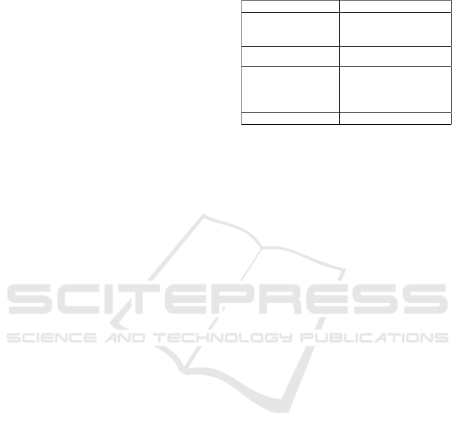
Figure 2: Specification: Individual instances may be con-
figured using customer exposed properties. Example: span
= 30 cm.
method from the specification of a product instance
to the end of the life cycle.
The specific business domain requires to separate
some of the RAMI phases into smaller parts because
they are implemented with different tools. It is pro-
posed to separate the calculation phase from the spec-
ification phase and the calibration phase from the sim-
ulation phase. Additionally, the decommission and
depollution phases have been added. This way the
entire life cycle of a product can be covered, not on
the level of product type but on the level of a single
product instance (digital twin). Consequently the sub-
sequent problem of interchanging the digital twin data
between organizations arises. This can be necessary
between business functions, if they are supported by
different companies. This topic will be discussed in
future studies.
4.1 Specification
In the specification phase the instantiation of a partic-
ular product instance from a base model is set up. Fol-
lowing the idea of a model based design, as defined in
(Wikipedia, 2020) the instantiation of a product in-
stance out of a product model is performed. Basic
concepts of that phase are customer exposed proper-
ties, which are properties of a product, that may be
modified by the customer and represent the specifica-
tion of a product instance.
Specification means to put a value different from
IN4PL 2020 - International Conference on Innovative Intelligent Industrial Production and Logistics
72
the prototype value into the specification data set in
the repository entry of the product instance. For in-
stance the span of the wing may be changed from 50
cm of the base model prototype to 30 cm. (Fig. 2
(top)).
The instance process binds the chosen values to
the base model properties and calculates an instantia-
tion of the product.
The structure calculation function transforms a set
of customer exposed property to the real shape of the
product which results in a new version of the instance
of the product (Fig. 2 (bottom)).
4.2 Calculation
After the specification of an instance, the next step
will be to calculate the presumptive functionality of
the product instance as far as it is possible from the
specified items only. For the model airplane busi-
ness domain different calculation groups can be dis-
tinguished:
Numerical Consistency. Checks whether all values
entered are in the correct numerical range.
Geometrical Consistency. Checks whether some
geometrical constraints are violated. For instance,
that the wing is not connected to the fuselage.
Aerodynamic Calculations. Checks the aerody-
namic balance of the plane. If not checked it is not
sure that the plane will fly.
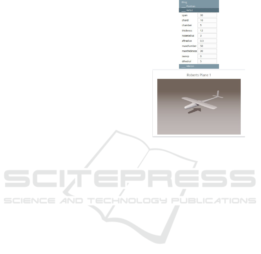
4.3 Calibration
Calculation will be followed by calibration. Calibra-
tion defined as the exposure of an instance to the op-
eration environment within the digital world. The in-
stance will be ”tested out” digitally. (G. Grabmair and
Aigner, 2014).
Different usage parameters settings are combined
and show the planned behavior in the calibration.
Back in the plane factory for example the rudder may
be deflected in its leftmost position. In case of air-
planes a CFD
2
System was bound to the building
block ”Aerodynamic Calibration”. CFD simulates the
airflow around the planes and shows the forces and
moments around the investigated object.
By post-processing the CFD results a model of the
aerodynamic behavior of the product instance (forces
2
Computational Fluid Dynamics is the discipline to sim-
ulate the dynamic flow around given objects.
Figure 3: Calibration: The instantiated plane is measured in
a digital wind channel to find out its aerodynamic charac-
teristics.
and moments) are deducted. Fig. 3 shows a
product instance in the calibration run.
From the meta level point of view the following
happens in the calibration function: By definition the
Industry 4.0 production process the usage of a single
(lotsize-1) product instance should be simulated be-
fore usage. Simulation means that the digital twin of
the product instance is exposed to operating environ-
ment to experience the functionality only by means of
digital instruments. This on the other hand requires
a valid simulation function of the operating environ-
ment. A model that contains how product instance
and environment interact with each other. To find this
model the calibration phase is used. From the result
of the CFD attitude change properties are calculated.
The values bound to this properties may be single val-
ues or entire functions that describe the behavior of
the object in its operating environment. Mainly this
are change rates at certain points of the aerodynamic
description function.
The aerodynamic model is used as a basis for the
following simulation.
4.4 Simulation
Once the digital twin, its attitude change properties
and the model of the operating environment for a
product instance are available a simulation can be
started. The simulation is important for the customer
to experience the behavior of the instance long before
the production happens. It helps to prevent miscon-
ceptions and a lack of usability. A significant reduc-
tion of development time can be gained as described
in (Green Car Congress, 2009)
Fig. 4 shows the simulation of a model airplane in
a light weighted flight simulator. In the top left corner
the operating parameters are displayed which makes
it possible to observe the physical properties during
the simulated operation. The result correspond to the
Infrastructure for an Integrated Industry 4.0 Life Cycle Spanning Design and Production Platform
73
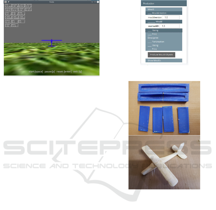
Figure 4: Simulation: Simulation of the product instance in
flightsimulator driven by a instance specific PyFME config-
uration.
customers’ expectations. From now on in the process
not only includes digital procedures.
4.5 Production
In this context production is defined by realizing a
specific product to make it usable. The steps before
this point are production-agnostic. The specified and
simulated product can be produced in several tech-
nologies, the process plans. A process plan consists
of production steps. Each and every step requires its
own parameters (e.g.: thickness of the perimeter of
a mold’s 3D print). Similar to life cycle phases the
model used here is simple but enables to see the pro-
cess integration.
It is evident to propose a technical architecture
where every single production step gets its parameter
information by interpretation of values out of a repos-
itory data structure. The digital twin is able to come
along with the product instance all the way through
its life cycle.
Although only one production process is realized
at the moment (printed molds), the structure in the
esstone factory is designed to hold a set of production
processes, each consisting of several steps (Fig. 5).
The finally printed molds (Fig. 6 top) may be filled
with foam. After applying a silicon spray as a parting
agent the plane can be produced with two component
PU Foam (1:6 expansion rate)(Fig. 6 bottom).
4.6 Supporting Further Steps
As stated above the actual state of development in
the project ends after the production business func-
tion where the user/customer may 3D print a mold
for the specified model plane. The complete life cy-
cle as proposed in RAMI 4.0 covers some more life
Figure 5: Production: Shows two processes (Mold and Di-
rectprint) and production steps Moldcreation, Slicing, Print.
Figure 6: Production: 3D printed moulds and produced
plane (scaled for test).
cycle stages: Procurement, Quality Assurance, Deliv-
ery, Operation, Maintenance.
Additionally, two more stages can be seen driven
by the actual ecologicalization of many discussions:
Decommission, Depollution.
Each of these stages have a special characteristic
even though for all of them it should be able to be in-
corporated into presented common framework. These
aspects will be covered in next steps of this project.
5 REPOSITORY
As described in detail in (T. Breckle et al., 2014) and
(ref, ) there are many challenges in the vertical inte-
gration of a production stream throughout the entire
IN4PL 2020 - International Conference on Innovative Intelligent Industrial Production and Logistics
74

life cycle. On the one hand the proliferation of data
from one stage to the other (specification to produc-
tion). On the other hand and even more important is
the propagation of constraints that one step requires
and another has to interpret and obey. It is especially
valid for the backward propagation from later steps to
earlier steps, e.g.: The specification should honor the
restrictions the 3D mold printing process imposes.
A general, common and light weighted accessible
repository can be established. In the showcase fac-
tory a single XML is used as repository data struc-
ture. This will be reformulated in a model based data
structure that is accessible from a distributed environ-
ment. A common technically defined protocol will be
proposed.
6 CONCLUSION, FURTHER
WORK
In this paper a layered generalized approach is shown
to model the vertical integration of a lotsize-1 produc-
tion throughout the entire life cycle of a product. In
four abstraction layers the variability of the deployed
instruments and organizational settings are arranged
into an concise model. A subset of business func-
tions were described the life cycle process consists of.
The results of the referenced model factory were pre-
sented.
The further work will concentrate on the follow-
ing research threads: (a) Completing the showcase es-
stone.flights; (b) Define a data structure and protocol
to be able to distribute the life cycle stages to different
organizations/companies; (c) Completing the analysis
of all proposed life cycle stages; (d) Investigate the or-
ganizational aspects, to find out what does it mean to
be a ”product designer” in the proposed framework.
REFERENCES
Interoperability across digital manufacturing platforms.
https://www.digicor-project.eu/post/2018/03/22/
platform-interoperability; Last accessed 5.3.2020.
Bundesministerium f
¨
ur Bildung und Forschung, editor
(2013). Zukunftsbild Industrie 4.0, Bonn.
F. Belkadi et al. A knowledge-based collaborative platform
for pss design and production. CIRP Journal of Man-
ufacturing Science and Technology. [Online; accessed
6.9.2020].
FH Vorarlberg (2020). Digital factory vorarlberg. https:
//www.fhv.at/en/research/digital-factory-vorarlberg.
[Online; accessed 4.3.2020].
Fraunhofer Austria Research (2018). Stabile produktion
in wandlungsf
¨
ahigen zellenorientierten montagesyste-
men durch einen digital twin. https://projekte.ffg.at/
projekt/2920209. [Online; accessed 5.3.2020].
G. Grabmair, S. Mayr, M. H. and Aigner, M. (2014). Model
based control design – a free tool-chain. In European
Control Conference (ECC), Strasbourg, France.
Gesellschaft f
¨
ur Informatik (2017). Digitaler zwilling.
https://gi.de/informatiklexikon/digitaler-zwilling/.
[Online; accessed 5.3.2020].
Green Car Congress (2009). General motors devel-
oped two-mode hybrid powertrain with mathworks
model-based design; cut 24 months off expected
dev time. https://www.greencarcongress.com/2009/
10/general-motors-developed-twomode-hybrid
-powertrain-with-mathworks-modelbased-
design-cut-24-months-of.html. [Online; accessed
6.9.2020].
Plattform 4.0 (2016). DIN SPEC 91345:2016-04 - Ref-
erenzarchitekturmodell Industrie 4.0 (RAMI4.0).
https://www.plattform-i40.de/PI40/Redaktion/DE/
Downloads/Publikation/din-spec-rami40.html. [On-
line; accessed 26.2.2020].
Schweichhart, K. (2016). Reference Archi-
tectural Model Industrie 4.0 (RAMI 4.0).
https://ec.europa.eu/futurium/en/system/files/ged/
a2-schweichhart-reference architectural model
industrie 4.0 rami 4.0.pdf. [Online; accessed
26.2.2020].
Selim, E. (2019). Industrie 4.0 – gedanken
¨
uber die zukunft
der produktion in europa und aktuelle forschungsak-
tivit
¨
aten in der industrie 4.0 pilotfabrik der tu wien,
construction goes digital.
T. Breckle et al. (2014). The evolving digital factory – new
chances for a consistent information flow. In 12th
CIRP Conference on Intelligent Computation in Man-
ufacturing Engineering, Gulf of Naples, Italy. CIRP
ICME ’18.
TU Graz (2020). smartfactory@tugraz. http://www.
smartfactory.tugraz.at/. [Online; accessed 4.3.2020].
Wikipedia (2020). Model-based design. https://en.
wikipedia.org/wiki/Model-based\ design. [Online;
accessed 6.9.2020].
Infrastructure for an Integrated Industry 4.0 Life Cycle Spanning Design and Production Platform
75
