
Solar Power Plant Tracker Upgrade and MPPT Control with Internet of
Things
Didik Notosudjono
1
, Hazairin Samaulah
2
Muhamad Nopriansy
1
, Bagus Dwi Ramadhon
1
, Dimas
Fiddiansyah
1
, Asri
1
1
Universitas Pakuan, Indonesia
2
Universitas Tridinanti Palembang, Indonesia
Keywords:
LDR, solar panel, dual-axis tracker, Atmega328P-PU, MPPT, IoT, Internet of Things.
Abstract:
To maximize sunlight absorption by forming a perpendicular axis between the sun and the solar panel. A
method which could be implemented on the solar panel system that could follow the sun’s movement is
needed. On this design, the system uses a light diode sensor (LDR) that functions as the light detector, an
Atmega238P-PU microcontroller as the command logic storage, and a servo motor as a mover to dislocate the
position of the solar panel with Internet of Things (IoT). In the solar panel test which runs for 11 hours using
the dual-axis solar panel tracker has yield a power of 9.4 W and after passing the MPPT control battery, it
gives an average of 10.6 W. Compared to using a static solar panel method, it only yields a power of 6.8 Watt,
and after passing the MPPT control battery, it gives an average power of 9.25 W.w
1 INTRODUCTION
1.1 Background
To maximize the absorption of sunlight, a method
which forms a perpendicular axis between solar panel
and sunlight is needed. Hence the need to make a
model that could be implemented into a solar panel
system that could follow the sun’s direction is crucial.
There is also an excess power from the solar panel
into the battery itself, so a MPPT (Maximum Power
Point Tracker) control battery is also needed. While
the use of dual-axis solar tracker is already discussed
in past studies, the implementation of said dual-axis
tracker using Internet of Things (IoT) to be remotely
controlled through a website haven’t been developed.
1.2 Model Simulation
The methodology used in this study is to design a pro-
totype Solar Power Plant Tracker with the IoT-based
MPPT battery using ATMEGA328P-PU microcon-
troller. The system are designed to calculate the sun
position at anytime, at any location, and any day of
the year.
2 THEORETICAL BASIS
2.1 Photovoltaic (Solar Cell)
Photovoltaics are able to convert photon energy into
electrical energy. One solar cell usually could pro-
duce DC voltage around 0.5 – 2 V when illuminated.
Several solar cells will need to be arranged in a se-
ries to get a larger desired voltage(Notosudjono and
Adzikri, 2018).
2.2 Solar Panel Tracker System
Each square meters in the solar panel surface area
that faces the sun could harvest around 1000 W solar
power (assuming 100% efficiency). Thus, to increase
the solar panel’s energy efficiency, a simple but accu-
rate solar detector mechanism is needed as seen in the
Figure 1 below, known as tracker mechanism.
Notosudjono, D., Samaulah, H., Nopriansy, M., Ramadhon, B., Fiddiansyah, D. and Asri, .
Solar Power Plant Tracker Upgrade and MPPT Control with Internet of Things.
DOI: 10.5220/0009881602190223
In Proceedings of the 2nd International Conference on Applied Science, Engineering and Social Sciences (ICASESS 2019), pages 219-223
ISBN: 978-989-758-452-7
Copyright
c
2020 by SCITEPRESS – Science and Technology Publications, Lda. All rights reserved
219

(Prinsloo and Dobson, 2015) In the following fig-
ure is the solar trajectory illustration.
Figure 1: Solar trajectory illustration.
The Sun follows a certain path when seen from a
geographical location. A sun tracker mechanism is
used to find the sun’s position in a certain location
to keep the solar panel perpendicular against the sun.
(Prinsloo and Dobson, 2015) Solar declination can
also be defined as the angle between the line joining
the centers of the Sun and the Earth and its projection
on the equatorial plane. The solar declination changes
mainly due to the rotation of Earth about an axis. It’s
maximum value is 23.4°Con December and the min-
imum is -23.4°C on June 21st (Mansour et al., 2015;
Elsherbiny et al., 7 09).
2.3 Automatic Photovoltaic Tracking
System
Automatic Photovoltaic system is designed using
dual-axis tracker. Dual axis trackers have two de-
grees of freedom that act as axes of rotation. These
axes are typically normal to one another. Two-axis
tracker tracks the daily east to west movement of
the sun and the daily declination movement of the
sun. Two common implementations are TTDAT (tip-
tilt dual axis trackers) and AADAT (azimuth-altitude
dual-axis trackers) (Elsherbiny et al., 7 09).
This tracker gives the possibility for automatic
measuring of direct solar radiation with a pyrheliome-
ter. In the active operation mode, the tracker uses
the signal of a sun detecting linear sensor to control
the pointing (Roth et al., 2005). Two stepper motors
move the instrument platform, keeping the sun’s beam
at the center of the sensor.Duarte, et al. (Duarte et al.,
2011) designed a two axis sun tracking system. Fig-
ure 2 below shows Dual axis tracker.
space
Figure 2: Dual axis tracker.
2.4 Servo Motor
Servo motors have been around for a long time and are
used in many applications. They are small in size but
powerful and are very energy efficient. Servos con-
trol by sending an electrical pulse of variable width
(or pulse width modulation (PWM)) through control
wire. Servo motor could only turn 90°C in either di-
rection for a total of 180°C movement. The position
where the servo has the same amount of potential ro-
tation both in the clockwise or counterclockwise di-
rection is defined as the servo motor’s neutral position
(Ramadhan et al., 2018).
2.5 Maximum Power Point Tracker
(MPPT) Method
Tracking the maximum power point (MPP) of a pho-
tovoltaic array is an essential stage of a PV system
(Femia et al., 2008) . As such, many MPPT meth-
ods have been introduced and numerous variants of
each method have been proposed to overcome spe-
cific disadvantages. The methods all vary in complex-
ity, number of sensors required, digital or analogue
implementation, convergence speed, tracking ability,
and cost effectiveness(Babaa et al., 2014).
2.6 ATMEGA328P-PU Microcontroller
Pin Configuration
Atmega328P-PU has the ability to separate memory
for program code and for memory so that it can max-
imize work in parallelism, or commonly called Har-
vard architecture which only requires 5Vdc.
2.7 Internet of Things (IoT) Concept
The Internet of Things is envisioned to allow for the
interconnectivity of anyone and anything at anytime
and in anyplace. This connectivity should ideally be
possible using any service over any conduit, path or
ICASESS 2019 - International Conference on Applied Science, Engineering and Social Science
220
network. This is popularly referred to as The IoT
6A Connectivity Concept (Takpor et al., July; Perera
et al., 2013).
The IEEE IoT Community defines the Internet of
Things as: “. . . a self-configuring and adaptive sys-
tem consisting of networks of sensors and smart ob-
jects whose purpose is to interconnect “all” things,
including every day and industrial objects, in such
a way as to make them intelligent, programmable
and more capable of interacting with humans” (IEEE,
2015).
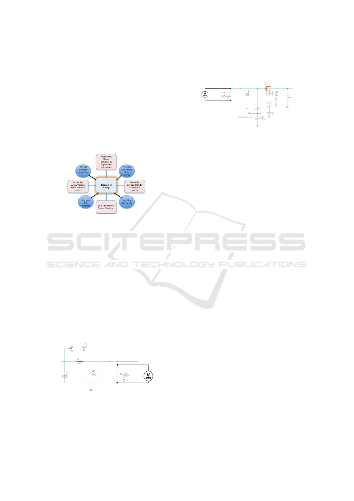
Figure 3. shows a structure of the connectivity
concept of IoT and some of IoT’s application areas.
Figure 3: IoT’s connectivity concept and application areas.
3 TESTING AND ANALYSIS
3.1 Solar Panel and Control MPPT Test
The Solar Panel Test and Control Battery Test with
MPPT method are conducted to determine the amount
of power output from the solar panel, before and after
passing MPPT control. In the MPPT control test, we
observe the current and the voltage detected by the
current and voltage sensors on the LCD display. This
is done by measuring directly on the output pin from
this MPPT control electrical circuit. Fig. 4 below
shows the output pin of the MPPT control.
Figure 4: MPPT Control Output pin measurement.
To determine the comparison or difference be-
tween the resulting voltage and current values where
the main source is the solar panel, the measurement
on the input pin of the MPPT control is needed so it is
not solely based on the current and voltage values dis-
played by the LCD. Fig. 5 below shows the input pin
of the control before passing through MPPT control.
Figure 5: MPPT Control Input pin measurement.
After the current and voltage data from using
tracker method and static method with and without
the MPPT control is obtained, we can obtain the the-
oretical power value from the solar panel by using Voc
and Isc as seen in the eq. 1 below :
SolarCellOut putPower = V
oc
∗ I
sc
(1)
The following 10 Wp solar panel test result using
the tracker method for 11 hours in the Figure 6 and
Figure 7 :
Solar Power Plant Tracker Upgrade and MPPT Control with Internet of Things
221
space
Figure 6: Solar Panel Tracker and MPPT Control Test for
11 hours.
Figure 7: Solar Panel Tracker and MPPT Control Test for
11 hours (extension).
As seen in the Figure 6 and Figure 7 above, the
average power from running the test for 11 hours can
be measured from 07.00 – 17.00 (Indonesian Western
Time) with a capacity of 10 W, 21.6 V open circuit
voltage (Voc) , and 0.61 A short circuit current (Isc).
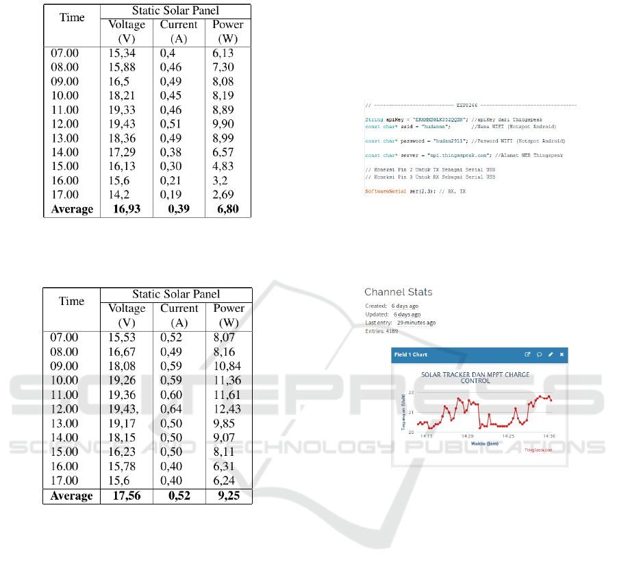
Using the static method without the MPPT control
for 11 hours, it generates 6.8 W by having a loss of
3.2 W = 10 W – 6.8 W. However, after passing MPPT
control battery, the power output becomes 9.25 W by
only having a 0.75 W loss.
In comparison by using a tracker method which
follows the same 11 hours test period from 07.00 –
17.00 (Indonesian Western Time), it can be seen that
the output voltage varies and that it generates a higher
power of 9.4 W with only a 0.6 W loss compared to
6.8 W using the static method. A 2.6 W difference
can be observed between them.
3.2 IoT with ESP8266 Module and
Thingspeak Web Test
ESP8266 Module automatically uploads data to the
web (http://thingspeak.com) periodically. In the fol-
lowing Fig. 8 is a program to connect the WiFi net-
work to ESP8266 to be uploaded to thingspeak web.
Figure 8: Program code using ESP8266.
The uploaded data is the voltage value data from
the solar panel according to time as seen in Fig. 9
below:
Figure 9: Voltage data uploaded using ESP8266.
4 CONCLUSION
After conducting observation and instrument test, it
can summarized as below:
1. In the solar panel test for 11 hours (07.00 – 17.00
Indonesian Western Time) using the dual-axis so-
lar panel tracker method has obtained the average
power output of 9.4 W before passing through the
MPPT control battery and 10.6 W after passing
through the MPPT control battery which matches
the maximum power on the solar panel of 10 W
p
.
2. In the solar panel test for 11 hours (07.00 – 17.00
Indonesian Western Time) using the static solar
panel method has obtained the average power out-
put of 6.8 W before passing through the MPPT
control battery and 9.25 W after passing through
the MPPT control battery which is close to the
maximum power on the solar panel of 10 W
p
.
ICASESS 2019 - International Conference on Applied Science, Engineering and Social Science
222

3. The Solar panel that uses the dual-axis tracker
method generates a higher power output of 9.4
W compared to 6.8 W generated by static method
which gives a difference of 2.6 W. This is due to
the static solar panel method not always perpen-
dicular to the sun, this problem could be solved
using the dual-axis tracker solar panel to ensure
the solar panel always perpendicular to the sun.
REFERENCES
Babaa, S. E., Armstrong, M., and Pickert, V. (2014).
Overview of maximum power point tracking control
methods for pv systems. Journal of Power and En-
ergy Engineering, 2:59–72. Published Online August
2014 in SciRes.
Duarte, F., Gaspar, P. D., and Gonc¸alves, L. C. (2011). Two
axes solar tracker based on solar maps controlled by
a low-power microcontroller. Journal of Energy and
Power Engineering, 5(7):671–6.
Elsherbiny, M. S., Anis, D. W. R., Hafez, D. I. M., and
Adel R. Mikhail, D. (2017-09). Design of single-axis
and dual-axis solar tracking systems protected against
high wind speeds. International Journal Of Scientific
& Technology Research, 6(09). ISSN 2277-8616.
Femia, N., Lisi, G., Petrone, G., Spagnuolo, G., and Vitelli,
M. (2008). Distributed maximum power point track-
ing of photovoltaic arrays: Novel approach and sys-
tem analysis. IEEE Transactions on Industrial Elec-
tronics, 55:2610– 2621.
IEEE (2015). Definition of iot. https://iot.ieee.org/
about.html. [Online; Accessed 03-May-2015].
Mansour, S., Anis, W., and Ismail, M. (2015). ISSN 2277-
8616, VOLUME 4, ISSUE 05.
Notosudjono, D. and Adzikri, F. (2018). Renewable Energy
Technology. UNPAK PRESS, Bogor.
Perera, A. Z., Christen, P., and Georgakopoulos, D. (2013).
Context aware computing for the internet of things: A
survey”. IEEE Communications Surveys & Tutorials,
16(1):414–454.
Prinsloo, G. J. and Dobson, R. T. (2015). Solar tracking.
stellenbosch: Solarbooks. Cambridge 2015 Book Edi-
tion, ISBN: 978–0–620–61576–1.
Ramadhan, M. G., Muttaqin, A., and Abidin, Z. (2018).
Maximum power point tracker (mppt) as a solar
cell power maximization method for solar boat eco-
charging. Seminar Nasional Teknik Elektro Universi-
tas Brawijaya.
Roth, P., Georgiev, A., and Boudinov, H. (2005). Cheap
two axis sun following device. Energy Conversion and
Management, 46(7-8):1179–92.
Takpor, T. O., Atayero, A. A., and Members, I. (July). In-
tegrating internet of things and ehealth solutions for
students’ healthcare. In Proceedings of the World
Congress on Engineering 2015 Vol I WCE 2015, vol-
ume 1, pages – 3,, London, U.K.
Solar Power Plant Tracker Upgrade and MPPT Control with Internet of Things
223
