
Innovation on Accessible and Low Cost Deflection Measurement Devices
Sukamto
1
, Juriah Mulyanti
1
and Nizar Achmad
2
1
Department of Mechanical Engineering, Janabadra University, Yogyakarta 55231, Indonesia
2
Department of Civil Engineering, Janabadra University, Yogyakarta 55231, Indonesia
{kamto ,jm.yanti, nizar achmad }@janabadra.ac.id
Keywords:
Optic mouse, deflection, innovation, low cost, measurement device modification
Abstract:
Deflection occurs mostly in structures, especially those that accept lateral loads. Excessive deflection can
cause damage, especially in the supporting structure therefore deflection must be measured but the deflection
measurement device is still expensive so the application is limited. Modification of the deflection measurement
device can be done using an optical mouse. The ability of optical mouse is expressed in the ability to scan the
number of points in each area, the bigger the smaller the displacement that can be measured. we use a cheap
mouse and the results show the mouse is able to measure deflection to accuracy of about 0.04 mm. Optical
mouse is cheap so it is expected to use it more widely, except for practitioners and universities, it is hoped that
it can also be used in vocational schools where the needs are large but the budget are limited.
1 INTRODUCTION
Monitoring of building structure deformation and
durability testing of materials and structures is a
very important process in development and produc-
tion with the aim of maintaining safety and strength
of the structure. Deflection occurs a lot in structures
that cause deformation so it needs to be monitored
by measuring it, especially when receiving maximum
loads. Fibre optic sensors used for monitoring bridges
(Yoneyama and Ueda, 2012). However the cost of fi-
bre optic sensors is too high and the installation of
the sensors is not easy for existing bridges. Another
approach to bridge deflection measurement is the use
of noncontact measurement method for example pho-
togrammetry, moir
´
e and laser scanning. A laser sys-
tem has a potential to measure deflection distribution
of bridge by scanning, however, at higher cost. Struc-
tural deflections represent a critical response param-
eter often measured for structural health monitoring
(Attanayake et al., 2011). Laser tracker records po-
sition coordinates at few discrete points while laser
scanner captures points of clouds representing de-
formed and undeformed shapes of a structure. These
technologies present distinctive advantages, capabili-
ties and limitations for field applications. Innovations
in deflection measurement devices that are low cost
(Guo and Wei, 2015) have to be created. This re-
search tries to make a cheap deflection measurement
device from a computer mouse. This aims to expand
the use of these devices in practical and academic en-
vironments. This research is limited to the use of op-
tical mouse to read shift points only in one direction
(Ali and Al-garni, 1996), (Simm et al., 2016). Com-
puter mouse that are modified only for one-way shifts.
It is mainly for measuring very small distances. De-
flection is very small, so it is precisely measured by
this tool. The depth of drilling holes that require high
accuracy can also be measured with this tool (Peng
et al., 2007). There are still many kinds of very small
distance measurements in daily work. This can be
seen from the development of tools that are getting
smaller in size so that the size needs to beaccurate in
the design and manufacture. Vocational school stu-
dents and university students really need to develop
skills in designing and manufacturing tools or ma-
chines. Of course this cannot be separated from the
use of measuring instruments. A cheap measuring in-
strument can be used even though it is not as precise
as a high-tech measuring instrument which of course
is expensive. However, the main objective is for stu-
dents to master the basic principles of measurement
that will not be separated from design. Cheap measur-
ing instruments are expected to be used more widely
so that it will increase the number of students who
have better skills to support their future. The rest of
this paper is structured as follows. After this intro-
duction of study, some previous study related to this
research are presented in theoretical background, ma-
terials and methods. Result and discussion presents
Sukamto, ., Mulyanti, J. and Achmad, N.
Innovation on Accessible and Low Cost Deflection Measurement Devices.
DOI: 10.5220/0009879601390142
In Proceedings of the 2nd International Conference on Applied Science, Engineering and Social Sciences (ICASESS 2019), pages 139-142
ISBN: 978-989-758-452-7
Copyright
c
2020 by SCITEPRESS – Science and Technology Publications, Lda. All rights reserved
139
findings and lessons from the test and the innovation
of measurement device. Finally, the conclusion pre-
sented including the implication of this study.
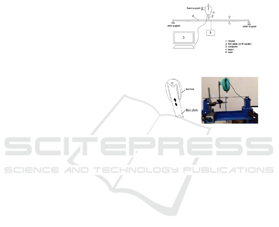
2 METHODOLOGY
The beam that receives the lateral load will be de-
flected according to the resultant direction of the load.
In this study the beam (4) only accepts the concen-
trated load (5) in the middle of the span in a vertical
direction. Therefore the point shift that occurs is only
one direction, namely vertical deflection. The load
is increased little by little so that the deflection that
occurs also increases. Deflection is a change in the
shape of the beam from horizontal to curve in the di-
rection y due to the vertical loading. The deformation
of the beam is very easily explained based on the de-
flection of the beam from its position before experi-
encing loading. Deflection is measured from the ini-
tial neutral surface to a neutral position after deforma-
tion occurs. The assumed configuration with neutral
surface deformation is known as the elastic curve of
the beam. Deflection that occurs along the beam can
be determined by making a form of equation which
is often called the curve deflection equation (or elas-
tic curve) of the beam. Structural systems are placed
horizontally especially for carrying lateral loads, i.e.
loads that work perpendicular to the axial axis of
the beam. Deflection is measured only at one point,
which is near the point of loading. Mouse is one of
the computer hardware that receives input in the form
of movement, button pressure and scroll. The mouse
used is a type of optics that does not use a mechanical
system at all but uses a laser beam to detect shifting
points. Technology in the optical mouse makes its
performance far more precise than the type of mouse
with a mechanical system. In recent years all digital
accessories are no exception the mouse leads to the
wireless trend. This mouse does not require a cable to
transmit movement signals but via wireless messages
received by the receiver device on the chip. With a
wireless mouse, the installation will be more flexible
on a series of research tools; it can even be installed
at long distances according to the specifications of the
mouse. But this type of mouse requires a battery in
operation, considering that it has no cable so that the
weight increases. Optical mouse (1) as a deflection
measurement device is connected to a beam near the
loading point. Shifting the point of the beam position
or deflection at the point being reviewed is recorded
directly at every second. The beam used is in the form
of iron plate or rectangular cross section beam. This
aims to make the beam only deflects in one direction
and does not experience bending in the other direction
due to loading. The plate cross section size is adjusted
to the length so that the plate is still in a straight state
when it is not loaded. This aims to fulfil the require-
ments in using the formula for deflection and slope
equations derived from the moment equation.
Figure 1: Deflection measurement scheme
Figure 2: Mechanism of shift reader
The slope along the beam is zero when there is no
load. Beams are supported by pins and roller orsim-
ple beams so that there must be no shift in the hori-
zontal direction. The load is applied to the beam little
by little. Every second there is an increase in load
and deflection. Additions to the load are carried out
slowly so that changes in data can be read clearly in
each second. Point shift will be recorded by the shift
reader consisting of a thin plate (2) mounted on the
mouse, but this plate can still be shifted. Data are
recorded and displayed on a computer screen (3) with
the help of program in the form of numbers and can
be graphed. The graph shows the amount of deflection
in each second. If an error occurs such as installing a
shift reader on a beam that is connected to a mouse
or a load movement that is not supposed to be, then it
can be analysed from the graphic form.
3 RESULT AND DISCUSSION
The test is carried out by giving a concentrated load
on 3 specimens in the form of iron plate. Iron plate
cross section is 22,0 mm x 2,7 mm. Load is given
manually because of the small beam size so it cannot
use load cell because the load is small. The load is
given gradually with a weight increase of 6.38 N as
many as three steps. The data taken from this study is
ICASESS 2019 - International Conference on Applied Science, Engineering and Social Science
140
the amount of deflection that occurs near the point of
loading. A shift reader that connects the mouse and
specimen is made of thin plates that are flexible or
from paper. The way the thin plate works is like using
a computer mouse that is installed with a small dis-
tance from the bottom side of the mouse. If the beam
has a deflection, the thin plate shifts so that there is a
point shift and recorded by the mouse. The underside
of the mouse is mounted on a rail so that the thin plate
can move or shift freely but the distance to the under-
side of the mouse remains The results of deflection
measurements are displayed in graphical form with
deflections on the axis and seconds on the ordinate as
follows.
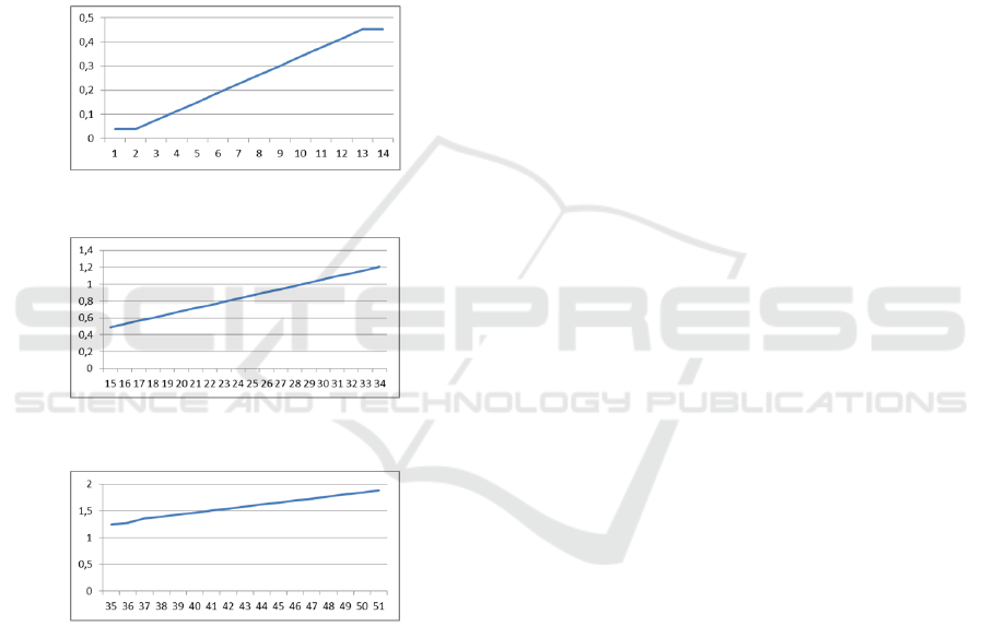
Figure 3: Graph of deflection with load start at 0 N
Figure 4: Graph of deflection with load start at 6,38 N
Figure 5: Graph of deflection with load start at 12,77 N
This measurement device has given result both
magnitude and graph of deflection. The mouse com-
puter is capable of detecting point shifts in very small
distances as shown in the table results of measure-
ment of deflection. In this study the shift of points
read only one direction, has not been able to read
the shift of points in various directions (Chen et al.,
2018) , (He et al., 2017), (Yang et al., 2018). There-
fore the test object must be ensured that there is no
shift in the other direction. This is done by attach-
ing the beam to a strong support even though the rod
is free to move because it is a simple beam. The
point shift on the beam from the horizontal position
to the deflection, which is downward, is read accu-
rately because the beam is not in contact with the
reader on the mouse, that is the laser (Szade et al.,
2015) , (Maekawa et al., 2016) . However, the mouse
is mounted on a fixed pedestal and does not shift fol-
lowing the shift of points on the beam. Therefore
the point that is read is only at a certain position so
that it is necessary to move the field along with the
beam because of the area of the beam is small when
viewed from the side. The field is in the form of a thin
plate tied to the beam and passed to the gap under the
mouse with the smallest possible distance. The point
shift is read from the side or direction perpendicular to
the direction of deflection. The cross section and the
length of the test object are chosen with the consid-
eration that they can be deflected in small loads and
not deflected due to the load itself. This is intended
so that the condition remains qualified in thecalcula-
tion of deflection (Ghuku and Saha, 2018). Another
consideration is that the beam must be weighed little
by little so that the increase in the deflection magni-
tude can be read every second. However, loading is
not done with load cell because load cell are only for
large load.
4 CONCLUSIONS
At the beginning of the load 0 N it turns out there has
been a deflection of 0,038 mm. This happens because
there is a place or container for loads that have their
own weight and has not carried load yet. As shown
in Figure 3, in the 1st and 2nd second, there had been
a deflection due to the weight of the container. This
is evidenced by the same initial conditions for spec-
imens 2 and 3, namely at the time of load 0 N the
amount of the deflection is 0,038 mm. The average
increase in the amount of deflection on the specimen 1
per second is 0,03 mm. With the same steps of exper-
iment for specimens 2 and 3, the average amount of
deflection increase is the same for each second which
is equal to 0,03 mm. The results of this study were
the cheap mouse can measure deflection with accu-
racy about 0,04 mm. This innovation of measurement
device proves that it will be easy and cheap for prac-
tical and academic environments.
Innovation on Accessible and Low Cost Deflection Measurement Devices
141

REFERENCES
Ali, A. E. and Al-garni, A. M. (1996). Evaluating the accu-
racy of laser levels for engineering surveying. Jour-
nal of King Saud University-Engineering Sciences,
8(1):121–130.
Attanayake, U., Tang, P., Servi, A., and Aktan, H. (2011).
Non-contact bridge deflection measurement: Applica-
tion of laser technology.
Chen, D.-M., Xu, Y., and Zhu, W. (2018). Identification of
damage in plates using full-field measurement with a
continuously scanning laser doppler vibrometer sys-
tem. Journal of Sound and Vibration, 422:542–567.
Ghuku, S. and Saha, K. N. (2018). Large deflection analysis
of curved beam problem with varying curvature and
moving boundaries. Engineering Science and Tech-
nology, an International Journal, 21(3):408–420.
Guo, Y. and Wei, L. (2015). Study of deflection measure-
ment for bridge using laser image technology. In 2015
3rd International Conference on Machinery, Materi-
als and Information Technology Applications. Atlantis
Press.
He, L., Lin, H., Zou, Q., and Zhang, D. (2017). Accurate
measurement of pavement deflection velocity under
dynamic loads. Automation in Construction, 83:149–
162.
Maekawa, A., Noda, M., Shintani, M., and Suzuki, M.
(2016). Development of noncontact measurement
methods using multiple laser displacement sensors for
bending and torsional vibration stresses in piping sys-
tems. International Journal of Pressure Vessels and
Piping, 137:38–45.
Peng, Y., Kumehara, H., and Zhang, W. (2007). Measure-
ment of drill point geometry by using laser sensor. In-
ternational Journal of Machine Tools and Manufac-
ture, 47(3-4):682–688.
Simm, A., Wang, Q., Huang, S., and Zhao, W. (2016). Laser
based measurement for the monitoring of shaft mis-
alignment. Measurement, 87:104–116.
Szade, A., Szot, M., and Ramowski, A. (2015). Mea-
surements of rope elongation or deflection in impact
destructive testing. Journal of Sustainable Mining,
14(4):211–218.
Yang, S., Ceylan, H., Gopalakrishnan, K., Kim, S., Taylor,
P. C., and Alhasan, A. (2018). Characterization of en-
vironmental loads related concrete pavement deflec-
tion behavior using light detection and ranging tech-
nology. International Journal of Pavement Research
and Technology, 11(5):470–480.
Yoneyama, S. and Ueda, H. (2012). Bridge deflection mea-
surement using digital image correlation with cam-
era movement correction. Materials transactions,
53(2):285–290.
ICASESS 2019 - International Conference on Applied Science, Engineering and Social Science
142
