
Study on the Effect Mno
2
-Deposited Carbon Nanofiber Mat and
Their Electrochemical Performance
Rizka Ayu Yuniar, Widiyastuti and Heru Setyawan
Chemical Engineering Department, Institut Teknologi Sepuluh Nopember, Kampus ITS Sukolilo, Surabaya 60111,
Indonesia
Keywords: MnO
2
, Carbon nanofibers, Electrospinning, Relative humidity, Capacitors
Abstract: Electric energy storage technology has evolved along with the increasing of the human need for portable
electronic devices and the development of electric-powered vehicles, one of which is capacitors. Material that
is often used for capacitors is activated Carbon and requires a binder, but the binder reduces the performance
of activated carbon as an electrode. An alternative material that can be used as a substitute for activated Carbon
is carbon black. One type of carbon black is acetylene black (AB). AB has been widely used as an additive
for conductive additives in the electrode preparation process because it has a large and low-density specific
area. Poly (vinyl alcohol) (PVA) has the physical properties of hydrophilic and semi-crystalline polymers.
Some of the advantages of PVA are having good thermal stability, chemical resistance, good physical
property, and excellent biocompatibility. Based on this, PVA is very interesting to be developed as an
electroactive composite matrix containing acetylene black. PVA/AB composite carbon nanofiber is made
using electrospinning techniques. Further development of carbon nanofiber as an electrode material needs
modification with the addition of MnO
2
through immersion techniques. The results of the SEM and XRD test
showed that MnO
2
was deposited on the carbon nanofiber surface area. The effect of adding MnO
2
can
increase the capacitance of the PVA/AB composite CNF.
1. INTRODUCTION
Electric energy storage technology has developed a
lot with the increasing human need for portable
electronic devices and the development of electric-
powered vehicles. One of them is a capacitor, which
is an innovation in the world of energy storage
devices that have large energy and power density,
large charge storage capacity, fast charge/discharge
process (Zhang and Zhao, 2009). These advantages
have been widely used in various fields such as digital
technology, electrical machinery, additional power
units, and energy storage equipment (Pech et al.,
2010). The material often used for capacitors is
activated Carbon because it has high cost-
effectiveness and performance efficiency (Gamby et
al., 2001). Activated carbon electrodes still need
binders such as organic material/polymers to bind
particles, but the presence of binders reduces the
performance of activated carbon as an electrode.
One alternative material that can be used as a
substitute for activated Carbon is carbon black.
Because carbon black has amorphous properties and
has several advantages, such as the price is relatively
low and has availability in various types and sizes.
Based on the process, black carbon consists of
furnace black, thermal black, channel black, and
acetylene black. Acetylene black (AB), prepared by
the thermal decomposition technique of acetylene,
whose electrical conductivity is known. In addition,
AB has been widely used as an additive to conductive
additives in the electrode preparation process because
it has a large specific area and low density (Gamby et
al., 2001). Previous research has made composites of
polyurethane (PU)/CB, polyaniline (PANI)/CB, and
Polyvinyl alcohol (PVA)/CB (Xiong et al., 2015).
Poly (vinyl alcohol) (PVA) has the physical
properties of hydrophilic and semi-crystalline
polymers. Some of the advantages of PVA are having
good thermal stability, chemical resistance, good
physical property, and very good biocompatibility
(DeMerlis and Schoneker, 2003; Koski, Yim, and
Shivkumar, 2004). Based on this, PVA is very
interesting to be developed as an electroactive
composite matrix containing carbon black. PVA/CB
composites have been carried out in the form of fiber
238
Yuniar, R., Widiyastuti, . and Setyawan, H.
Study on the Effect Mno2-Deposited Carbon Nanofiber Mat and Their Electrochemical Performance.
DOI: 10.5220/0009445602370243
In Proceedings of the 1st International Conference on Industrial Technology (ICONIT 2019), pages 238-244
ISBN: 978-989-758-434-3
Copyright
c
2020 by SCITEPRESS – Science and Technology Publications, Lda. All rights reserved

using electrospinning techniques, because they can be
applied in a variety of fields, have a wide specific area
and high porosity.
In recent years, the electrospinning technique has
been widely using to develop nanoscale diameter
fibers. Although the electrospinning easy to use, the
jet formation of the spinning dope is affected by the
electrospinning condition. There is a parameter
process that is influencing various fiber formation and
fiber properties. Moreover, to get form fiber from the
electrospinning with good characteristics, the
ambient condition surrounds the chamber has to be
controlled carefully during the electrospinning
process. Fundamental processing condition have
already reported which include applied voltage
(Demir et al., 2002; Lee et al., 2004; Zhao et al.,
2004), viscosity (Mit-uppatham, Nithitanakul and
Supaphol, 2004; Shenoy et al., 2005), surface tension
(Zheng et al., 2014) and conductivity and dielectric
constant (Choi, Xue,) (Choi et al., 2004; Xue et al.,
2014). Among the ambient parameter such as
temperature and relative humidity also the most
important influence the fiber formation. There is a
Polymer such as polystyrene fibers resulted in larger
diameter at higher humidity (Kim et al., 2004;
Fashandi and Karimi, 2012) and polyetherimide
(Ogulata and İçoğlu, 2013). Various of humidity also
generate porous fibers by electrospinning
polycaprolactone (PCL), poly L-lactic acid (PLLA)
and polyvinylpyrrolidone (PVP) (Yazgan et al.,
2017).
Manganese dioxide (MnO2) has many
applications in industrial fields, including reagents in
organic synthesis, as inorganic pigments in ceramics,
and as electrodes in batteries. The use of MnO2 as an
electrode has several advantages, including
inexpensive and environmentally friendly (Yu et al.,
2011). Recently, there are several combination
between Carbon with MnO2 including carbon
nanofiber (CNF)/MnO2 with redox reaction of
KMnO4 solution (Ma et al., 2016), CNT/MnO2 with
hydrothermal reaction of KMnO4 solution (Xia et al.,
2012) and ACNF/MnO2 (Wang et al., 2013).
Here, we reported the electrodes prepared via
electrospinning of PVA/AB into nanofiber mats,
which were heat treated. Before that, polyvinyl
alcohol (PVA) was examined at various relative
humidity conditions to obtain fiber shape, fiber
surface, and fiber diameter. MnO2 crystals were
deposited on the surface of the CNFs by the
immersing of aqueous KMnO4. The effect of MnO2
crystal on the surface morphology with a varied mass
ratio of CNFs versus KMnO4 and electrochemical
properties were investigated.
2 EXPERIMENTAL
2.1 Materials
Polyvinyl alcohol (PVA) technical grade and
acetylene black (AB) were purchased from SAP
chemicals and were used directly without further
purification. Potassium permanganate (KMnO4) was
purchased from Sigma Aldrich. All of the chemicals
or materials were used directly without further
purifications.
2.2 Synthesis of Carbon Nanofiber
The synthesis procedure for PVA/Acetylene Black
(AB) could be explained as the following. PVA
powder was mixed with distilled water under stirring
for about an hour at 80 °C. Then, Acetylene Black
was added to the PVA solution under constant stirring
for 30 min. The mixture was sonicated at 50 °C for 4
hours to achieve the solution. Then the solution was
injected into a 50 ml plastic syringe, which was fitted
in an electrospinning apparatus to start spinning the
PVA/AB solution. The spinning parameters were
high voltage 10 kV (positive) was applied to the tip
of syringe to achieve polymer jets, and negative was
applied to the rotating cylinder, nozzle inside
diameter 0.6 mm (23G), temperature in chamber 25
°C and relative humidity (RH) in chamber hold on 60
% where RH conditions were precisely regulated
using dried silica and dehumidifier. The feed rate of
the solution was controlled by means of a Cole
Parmer Scientific syringe pump at 1 mL/h. The
products were placed in a dry cabinet for 24 hours,
previously further characterization.
Samples of 50 mm 30 mm of electrospun
nanofiber mats were placed into a sealed glass jar for
iodine treatment in a muffle furnace (Themolyne) at
80 °C for 24 h. The glassed jar was contained iodine
crystal with mass ratio iodine crystal versus mats of
1:2 to vaporize the iodine. After that, the sample was
removed from the oven and naturally cooled down to
room temperature. Iodine treatments are necessary for
the preparation of carbon nanofiber with the desired
morphological and structure.
The nanofiber mats were thermostabilized and
carbonized in a Lindberg tubular furnace with heating
procedures as follows: (1) The temperature was
increased from 30 to 200 °C; (2) 200 to 400 °C; (3)
400 to 600 °C, each step the temperature was holding
for 15 minutes. (4) The temperature was increased
from 600 to 800 °C; (5) the temperature remained at
800 °C for an hour; and (6) the sample was cooled
down to room temperature. During the carbonization
Study on the Effect Mno2-Deposited Carbon Nanofiber Mat and Their Electrochemical Performance
239
process, constant nitrogen flow was maintained
through the tube.
2.3 MnO
2
deposition on surfaces
carbon nanofibers (CNFs)
MnO
2
was deposited on the surface of the carbon
nanofibers by the simple method degradation of
KMnO
4
, as represented in the literature (Ma et al.,
2016). Firstly, a certain amount of different KMnO
4
concentration was dissolved in 10 mL distilled water
and stirred until the KMnO
4
was fully dissolved.
Mass ratios for every two CNFs versus KMnO
4
were
1: 1 and 1: 2. The CNF was immersed in the KMnO
4
solution at 65 °C for 4 hours. During immersion, the
color of the solution changed from purple into brown.
The MnO
2
-deposited CNFs (CNFs-MnO
2
) were
removed from the solution, rinsed with distilled
water, and dried overnight in an oven at 80 °C. The
MnO
2
-CNFs obtained under this condition using the
KMnO
4
concentrations listed above are denoted to as
CNF-MnO
2
(1:1) and CNFs-MnO
2
(1:2). Note that
the mass ratio in here represents the mass ratio of
CNFs mat to KMnO
4
during preparation.
3 RESULT & DISCUSSION
3.1 The effect of relative humidity on
PVA nanofiber
Relative humidity (RH) is one of the parameters
prosses that affected morphology nanofiber.
Temperature and humidity of the environment are
very much influencing the physical characteristic due
to the effect of solvent vaporization and solution
sensitivity on the drying rate of the solution. This
includes the performance of nanofiber forming i.e.,
smooth fiber, bead or beadless, and fiber diameter.
Interaction between the solution and the surrounding
water vapor should be considered on fiber diameter.
In this study, the effect of RH on morphology
nanofiber (diameter and shape) is investigated based
on PVA polymer solutions with a concentration of 15
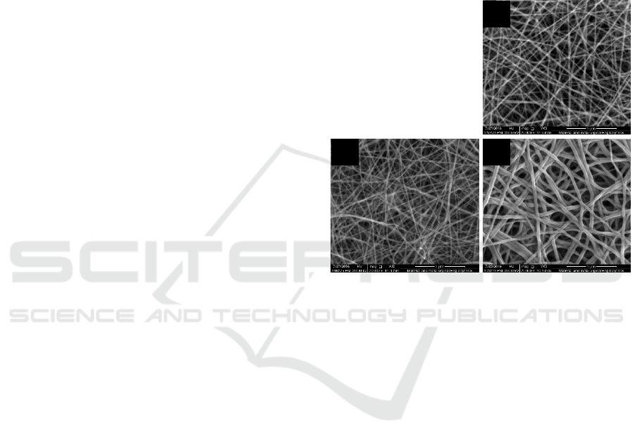
% w/v. As shown in Figure 1, smaller diameter PVA
fibers spun from the higher humidity was found from
the same concentration. A possible reason for this
condition is due to slower solvent evaporation that
water condensing on the surface of electrospinning
was absorbed into the solution from the environment
during the electrospinning process, and it was related
to lower viscosity. Mean fiber diameter was shown to
reduce from 300 nm at 50 % relative humidity to 250
nm at 70 % relative humidity. Nevertheless, the lower
relative humidity may also be led to rapid solvent
vaporization that may cause an increase in the
solidification rate. Thus, the larger fiber diameter has
resulted.
The chamber of electrospinning is not a vacuum,
and there are many slots on the wall. Therefore in the
next step, the relative humidity was held on at 60%,
caused it is relatively simple to control with
dehumidifier during the electrospinning process.
Figure 1 : SEM images of PVA 15 % w/v electrospun
product at RH : (a) 70 % (b) 60 % (c) 50%
3.2 Synthesis Carbon Nanofiber/MnO
2
MnO2 was deposited by immersing Carbon
Nanofiber (CNF) composites in the KMnO
4
solution.
Carbon nanofibers were formed from the mixture
between PVA and Acetylene black (AB) with AB
concentration 10 and 15 wt. % based on PVA powder.
In the previous study, AB concentration influenced
the shape and diameter fibers (Yuniar et al., 2019).
The AB concentrations listed above are denoted to as
10CNFs-MnO
2
(1:1), 10CNFs-MnO
2
(1:2) , 15CNFs-
MnO
2
(1:1) and 15CNFs-MnO
2
(1:2).
Figure 4 shows the SEM images CNFs-MnO
2
composites where there are particles deposited on the
surface of CNF, which indicate the presence of
MnO
2
. After depositing MnO
2
by a redox reaction
with KMnO
4
solution, the morphology of CNFs in
contrast to that of CNFs on the previous study that
CNFs before immersing was smooth fibers (Yuniar et
al., 2019). During the immersion of CNF in the
KMnO
4
solution, the color changed from purple to
dark brown that indicates MnO
2
had been formed
(Fuenmayor et al., 2013). For 10CNFs-MnO
2
(1:1)
PVA 15 % w/v
a
b c
ICONIT 2019 - International Conference on Industrial Technology
240
and 15CNFs-MnO
2
(1:1), the surface area of CNFs
became rough, and nanoparticles of MnO
2
can be
exposed, as shown in Figures 1a and 1c. For 10CNFs-
MnO
2
(1:2) and 15CNFs-MnO
2
(1:2), which is
prepared in a higher mass ratio of KMnO
4
, the large-
sized particle of MnO
2
are deposited on the fiber
surface. Figures 1b and 1d show that the particles of
MnO
2
appear uneven on the surface of the fiber and
are more likely to form agglomerates around fiber
nods. It tends to make a layer above the fiber surface
so that the fiber structure is covered by the layer
above it. The previous study reported that smaller
particles like microscale that have smooth texture on
the surface, it takes adhesion of particle initially on
the surface, and that means the particle MnO
2
(Chow,
2003). When the carbon fibers were immersed in a
KMnO
4
solution at 65 °C, CNFs was directly reduced
the KMnO
4.
The overall reaction is described as
follows (Jin et al., 2007):
4KMnO
4
+ 3C + H
2
4MnO
2
+ K
2
CO
3
+ 2 KHCO
3
Carbon fibers provided not only as a reagent.
Based on the redox reaction of KMnO
4,
carbon fibers
not only as a reagent but also as substrate and agent
collector of the current. The rough surfaces of carbon
fibers, it is becoming the new of surfaces carbon
fibers, and it causes the carbon fibers are intrinsically
less positive (Chi et al., 2014). During the process of
nucleation and MnO
2
nanoparticle, the more enough
nucleation area, the more area can wipe out the
essence of creating a new surface (Chi et al., 2014).
The structure of the MnO
2
particle on the surface
carbon nanofibers was analyzed by XRD analysis
(X’pert PRO PANalytical). As shown in Figure 3, the
XRD patterns of CNFs-MnO
2
shows the two broad
diffractions approximately 17.5° and 25.3°. The
spectrum of the carbon nanofibers (CNFs) can be
indexed (002), which represented the graphite carbon
structures. Broad peak diffraction revealed that the
size of graphite might be in the nanometer scale and
the degree of graphitic relative low (Zhou et al.,
2010). The diffraction peak at 36.6° associated with
the (101) crystallographic planes of ramsdellite-type
of MnO
2
(JCPDS 39-375)
(Ghodbane, Pascal and
Favier, 2009)
.
Nevertheless, the peak just appeared in
10CNFs-MnO
2
(1:1). Consequently, CNFs-MnO
2
was reheated on tubular furnance at 300 °C for 1 h
under constant nitrogen flow. It might be removed
impurities of the CNFs-MnO
2.
Figure 2 : SEM images after immersing KMnO4 solution
and dried at 80 °C : (a) 10CNFs-MnO2 (1:1) (b) 10CNFs-
MnO2 (1:2) (c) 15CNFs-MnO2 (1:1) (d) 15CNFs-MnO2
(1:2)
Figure 3 : XRD patterns after immersing KMnO4 solution
and dried at 80 °C : (a) 10CNFs-MnO2 (1:2) (b) 10CNFs-
MnO2 (1:1) (c) 15CNFs-MnO2 (1:2) (d) 15CNFs-MnO2
(1:1)
Figure 4 shows the XRD patterns of CNFs-MnO
2
that reheated at 300 °C. The two broad diffractions
approximately at 36.6° and 44.4° in the spectrum can
be indexed (101) and (210), respectively, represent
the presence of ramsdellite-type MnO
2
at all the
samples (JCPDS 39-375) (Ghodbane, Pascal and
Favier, 2009). All of the peaks in the spectrum are
broad (poor crystallinity), and weak intensity, due to
typically adhesive MnO
2
nanoparticle (Ma et al.,
2016) yet the peaks from XRD analysis proved the
presence of MnO
2
in four samples. XRD pattern of
15CNFs-MnO
2
(1:2) has sharper peaks than those of
15CNFs-MnO
2
(1:1), 10CNFs-MnO
2
(1:2) and
10CNFs-MnO
2
(1:1), indicating that MnO
2
on the
surfaces of 15CNFs-MnO
2
(1:2) might have a higher
a
b
c
d
Study on the Effect Mno2-Deposited Carbon Nanofiber Mat and Their Electrochemical Performance
241
degree of crystallinity. Nevertheless, the nanofiber
structure is lost when reheated at 300 °C. As shown
in Figures 5a and 5b, the 10CNFs-MnO
2
(1:1) and
10CNFs-MnO
2
(1:1) surface fiber became rough. The
structure nanofibers were completely gone.
Figure 4 : SEM images after immersing KMnO4 solution
and dried at 300 °C : (a) 10CNFs-MnO2 (1:1), (b) 10CNFs-
MnO2 (1:2), (c) 15CNFs-MnO2 (1:1), and (d) 15CNFs-
MnO2 (1:2)
Figure 5 : SEM images of samples (a) 10CNFs-MnO
2
(1:1), (b) 10CNFs-MnO
2
(1:2), (c) 15CNFs-MnO
2
(1:1), and (d) 15CNFs-MnO
2
(1:2) after immersing
KMnO
4
solution and dried at 300 °C
To evaluate the electrochemical performance of
CNFs-MnO2 as electrodes in capacitors, cyclic
voltammetry (CV) measurements (Autolab PGSTAT
302N) were used on the CNFs-MnO
2
in a two split
electrode system while using 1 M Natrium thiosulfate
(Na
2
S
2
O
3
) as an electrolyte. The CV curve was
performed from -1 to 1 volt at scan rates of 100 mV.s-
1. The capacitance was estimated from the results of
CV curves using the equation /
, where the I is the current, ʋ is applied
potential, is the mass of the CNFs-MnO
2
electrode,
is the scan rate, and is the potential delta window
for the measurement of CV. In the two split electrode,
the aluminum band was sharped circular with
diameter 12 mm and used nanocellulose paper that
soaked in the electrolyte solution for 24 hours as the
separator for CV measurements. This measurement
was operated without a binder.
Figure 6: CV curves of the CNF-MnO
2
that dried at 300 °C
As shown in Figure 6, CV plots revealed the area
of 15CNFs-MnO
2
(1:2) is larger than others. It might
be 15CNFs-MnO
2
(1:2) acquired higher crystalline
then others with uniform distribution of that would
facilitate for reversible ion phenomenon, which is
proved by XRD pattern as shown in Figure 4. It is
showed that the CNF after immersing KMnO
4
solution that growth MnO
2
particle on the surfaces of
fibers able to increase the capacitance. The high
capacitance can be associated with the existence of
MnO
2
among porous structures that able to cut off the
electron diffusion path to provide ion and electron
exchange. That means the redox reaction can be
increased. Nevertheless, these capacitance values
were relatively low compared to other capacitors'
electrodes. It is caused the relatively poor electrical
conductivity of the MnO
2
decorated on the surface of
CNFs. MnO
2
possess with low crystalline was
resulted in low concentration KMnO
4
that used for
immersing carbon nanofiber. The capacitances of
CNFs-MnO
2
are shown in Table 1.
Table 1 : Capicatance of CNF and CNFs-MnO
2
Variable Capacitance (µF/g)
CNF 27
15CNFs-MnO2 (1:1) 32
15CNFs-MnO2 (1:2) 231
10CNFs-MnO2 (1:1) 36
10CNFs-MnO2 (1:2) 29
a b
c
d
ICONIT 2019 - International Conference on Industrial Technology
242

4. CONCLUSIONS
The study showed that during electrospinning, the
diameter of nanofibers could be arranged by relative
humidity. MnO
2
nanocrystals were successfully
deposited on the surfaces of CNFs by the redox
reaction of immersing the KMnO
4
solution. The
electrochemical performance of CNFs-MnO
2
designated might be capable of electrodes in a
capacitor with optimization.
ACKNOWLEDGMENTS
The authors are grateful for the financial support
provided by the Ministry of Research, Technology,
and Higher Education of the Indonesia Government
Directorate of research and public service through the
research grant under Contract No.
5/E1/KP.PTNBH/2019.
REFERENCES
Chi, H. Z. et al. (2014) ‘Direct growth of MnO 2 on carbon
fiber cloth for electrochemical capacitor’, JOURNAL
OF ALLOYS AND COMPOUNDS. Elsevier B.V.,
587, pp. 354–360.
Choi, J. S. et al. (2004) ‘Effect of organosoluble salts on the
nanofibrous structure of electrospun poly(3-
hydroxybutyrate-co-3-hydroxyvalerate)’, International
Journal of Biological Macromolecules, 34(4), pp. 249–
256.
DeMerlis, C. C. and Schoneker, D. R. (2003) ‘Review of
the oral toxicity of polyvinyl alcohol (PVA)’, Food and
Chemical Toxicology, 41(3), pp. 319–326.
Demir, M. M. et al. (2002) ‘Electrospinning of
polyurethane fibers’, Polymer, 43(11), pp. 3303–3309.
Fashandi, H. and Karimi, M. (2012) ‘Pore formation in
polystyrene fiber by superimposing temperature and
relative humidity of electrospinning atmosphere’,
Polymer, 53(25), pp. 5832–5849.
Fuenmayor, C. A. et al. (2013) ‘Encapsulation of R-(+)-
limonene in edible electrospun nanofibers’, Chemical
Engineering Transactions, 32, pp. 1771–1776.
Gamby, J. et al. (2001) ‘Studies and characterisations of
various activated carbons used for carbon/carbon
supercapacitors’, Journal of Power Sources, 101(1), pp.
109–116.
Ghodbane, O., Pascal, J. L. and Favier, F. (2009)
‘Microstructural effects on charge-storage properties in
MnO 2-based electrochemical supercapacitors’, ACS
Applied Materials and Interfaces, 1(5), pp. 1130–1139.
Jin, X. et al. (2007) ‘Nanoscale microelectrochemical cells
on carbon nanotubes’, Small, pp. 1513–1517.
Kim, G. T. et al. (2004) ‘Effect of Humidity on the
Microstructures of Electrospun Polystyrene
Nanofibers’, Microscopy and Microanalysis.
2004/08/01. Cambridge University Press, 10(S02), pp.
554–555.
Koski, A., Yim, K. and Shivkumar, S. (2004) ‘Effect of
molecular weight on fibrous PVA produced by
electrospinning’, Materials Letters, 58(3), pp. 493–497.
Lee, J. S. et al. (2004) ‘Role of molecular weight of atactic
poly(vinyl alcohol) (PVA) in the structure and
properties of PVA nanofabric prepared by
electrospinning’, Journal of Applied Polymer Science.
John Wiley & Sons, Ltd, 93(4), pp. 1638–1646.
Ma, X. et al. (2016) ‘Electrospun lignin-derived carbon
nanofiber mats surface-decorated with MnO2
nanowhiskers as binder-free supercapacitor electrodes
with high performance’, Journal of Power Sources.
Elsevier B.V, 325, pp. 541–548.
Mit-uppatham, C., Nithitanakul, M. and Supaphol, P.
(2004) ‘Effects of Solution Concentration, Emitting
Electrode Polarity, Solvent Type, and Salt Addition on
Electrospun Polyamide-6 Fibers: A Preliminary
Report’, Macromolecular Symposia. John Wiley &
Sons, Ltd, 216(1), pp. 293–300.
Ogulata, T. and İçoğlu, H. (2013) ‘Effect of Ambient
Parameters on Morphology of Electrospun
Polyetherimide (PEI) Fibers’, Tekstil ve Konfeksiyon,
23, pp. 313–318.
Pech, D. et al. (2010) ‘Ultrahigh-power micrometre-sized
supercapacitors based on onion-like carbon’, Nature
Nanotechnology, 5(9), pp. 651–654.
Pelipenko, J. et al. (2013) ‘The impact of relative humidity
during electrospinning on the morphology and
mechanical properties of nanofibers’, International
Journal of Pharmaceutics, 456(1), pp. 125–134
Shenoy, S. L. et al. (2005) ‘Role of chain entanglements on
fiber formation during electrospinning of polymer
solutions: good solvent, non-specific polymer–polymer
interaction limit’, Polymer, 46(10), pp. 3372–3384. doi:
https://doi.org/10.1016/j.polymer.2005.03.011.
Wang, J.-G. et al. (2013) ‘A high-performance asymmetric
supercapacitor based on carbon and carbon–MnO2
nanofiber electrodes’, Carbon, 61, pp. 190–199. doi:
https://doi.org/10.1016/j.carbon.2013.04.084.
Xia, H. et al. (2012) ‘Hydrothermal synthesis of
MnO2/CNT nanocomposite with a CNT core/porous
MnO2 sheath hierarchy architecture for
supercapacitors’, Nanoscale Research Letters, 7(1), p.
33.
Xiong, Z. et al. (2015) ‘Poly ( ethylene terephthalate )/
Carbon Black Composite Fibers Prepared by
Electrospinning’, Chinese Journal of Polymer Science,
33(9), pp. 1234–1244.
Xue, N. et al. (2014) ‘Rapid Patterning of 1-D Collagenous
Topography as an ECM Protein Fibril Platform for
Image Cytometry’, PLOS ONE. Public Library of
Science, 9(4), p. e93590.
Yazgan, G. et al. (2017) ‘Steering surface topographies of
electrospun fibers: understanding the mechanisms’,
Scientific Reports, 7(1), p. 158.
Yu, G. et al. (2011) ‘Enhancing the Supercapacitor
Performance of Graphene/MnO2 Nanostructured
Study on the Effect Mno2-Deposited Carbon Nanofiber Mat and Their Electrochemical Performance
243

Electrodes by Conductive Wrapping’, Nano Letters.
American Chemical Society, 11(10), pp. 4438–4442.
Yuniar, R. ayu et al. (2019) ‘Formation of Carbon Fibres
From Polymer Poly ( vinyl alcohol )/ Acetylene Black
using Electrospinning Method Formation of Carbon
Fibres From Polymer Poly ( vinyl alcohol )/ Acetylene
Black using Electrospinning Method’, IOP Conf. Ser.:
Mater.Sci.Eng, 543, p. 012030.
Zhang, L. L. and Zhao, X. S. (2009) ‘Carbon-based
materials as supercapacitor electrodes’, Chemical
Society Reviews, 38(9), p. 2520.
Zhao, S. et al. (2004) ‘Electrospinning of ethyl–cyanoethyl
cellulose/tetrahydrofuran solutions’, Journal of Applied
Polymer Science. John Wiley & Sons, Ltd, 91(1), pp.
242–246.
Zheng, J. et al. (2014) ‘The Effect of Surfactants on the
Diameter and Morphology of Electrospun Ultrafine
Nanofiber’, Journal of nanomaterial, 687298, pp. 1–9.
Zhou, Z. et al. (2010) ‘Graphitic carbon nanofibers
developed from bundles of aligned electrospun
polyacrylonitrile nanofibers containing phosphoric
acid’, Polymer, 51(11), pp. 2360–2367.
ICONIT 2019 - International Conference on Industrial Technology
244
