
Design of Ground Vehicle System Semi-autonomous Preceder Type
for Straight Path and Circular Path using Fuzzy Logic Method
Illa Rizianiza, Adhe Yusphie Panca Tentra Sandika
Institut Teknologi Kalimantan
Keywords: Fuzzy Logic, Ground Vehicle, Semi-Autonomous.
Abstract: The development of the robotics system increase significantly. Recently, robotics become an opportunity for
people to use those in many activities, for instance, automatic control systems in the land, which can be
referred to as Unmanned Ground Vehicle (UGV). Unmanned Ground Vehicle (UGV) has several categories
based on autonomous systems provided, namely teleoperated, semi-autonomous, platform-centric, and
network-centric. In this study, the prototype of the UGV system is a semi-autonomous type using the fuzzy
logic method as a control system. The input of fuzzy logic is the distance between the prototype and
obstacle. However, the output variable is the action of UGV to control the safe distance from the obstacle.
The design fuzzy logic system has been integrated with the robotdyn UNO microcontroller device as a
controller of UGV. The test results showed that the prototype could keep tracking to control the distance
according to rule base fuzzy logic. The setpoint has been set up at 10 cm - 15 cm from the obstacle and the
results of the semi-autonomous system movement that has been applied in-ground vehicle prototype. The
average error is 9 cm. This number still intolerance in tracking control.
1 INTRODUCTION
The autonomous ground vehicle has a wide scope of
research consisting of the short, medium, and long-
range robots that have small and large sizes with the
aim of supervision in small sectors, surveys, and
others. In vehicles that have a large size, it is usually
controlled by a combination of artificial intelligence
and human operators at a considerable distance. So
far in Indonesia, the land vehicle movement system
is still fully controlled by humans with the value of
Human-Robot Interaction (HRI) of 100% or level 0,
especially in fields where the land has bad
conditions such as bumpy, uneven, there are many
obstacles and others. The autonomous ground
vehicle has profound theoretical-practical significant
in an intelligent transport system (Kiencke, 2001). In
autonomous ground vehicle technologies,
longitudinal control keeps it moving at the desired
speed by controlling throttle and brake coordinately.
However, the non-linearity and uncertainty in the
dynamic model of the vehicle introduce difficulties
in the design of a longitudinal controller with high
precision (Xiaolon, 2011).
In this paper, as an extension of an autonomous
ground vehicle designed and developed for the user,
the control system by fuzzy logic presented. This
vehicle used a fuzzy control system to the desired
track. Fuzzy logic has the ability to transform human
sematic processes into numerical machine processes.
Fuzzy logic provides a link between human intuition
and machine expression. Fuzzy control methods are
known as powerful, intelligent tools that can be used
for controlling complex nonlinear systems.
Performances of fuzzy controllers have been
presented in commercial products and industrial
control applications (Kim, 2013). In this paper, a
fuzzy control system has simulated to the straight
and circular path.
2 FUZZY LOGIC CONTROL
2.1 Fuzzy Logic
Fuzzy logic was first discovered by Prof. Lotfi
Asker Zadeh at a seminar at the University of
California, Berkeley, United States. Fuzzy logic is
made on the grounds that there is uncertainty in
which members cannot only be separated into
Rizianiza, I. and Sandika, A.
Design of Ground Vehicle System Semi-autonomous Preceder Type for Straight Path and Circular Path using Fuzzy Logic Method.
DOI: 10.5220/0009443401770183
In Proceedings of the 1st International Conference on Industrial Technology (ICONIT 2019), pages 177-183
ISBN: 978-989-758-434-3
Copyright
c
2020 by SCITEPRESS – Science and Technology Publications, Lda. All rights reserved
177
members (1) or not members (0). There are several
definitions of fuzzy logic, including:
1. Fuzzy logic is a logic used to explain
ambiguity and explain the logic of a set that
resolves the ambiguity.
2. Fuzzy logic provides a way to convert
linguistic statements into a numeric (Hirulkar,
2014).
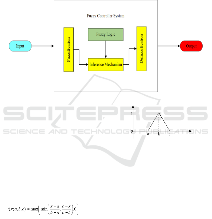
Figure 1: Fuzzy Controller
Fuzzy logic systems, which can be referred to as
Fuzzy Logic Control, have a composition of the
main setting components consisting of fuzzification,
rule base, mechanism of inference, and
defuzzification with each Fuzzy Logic Control
having input and output (Maghfiroh, 2016).
2.2 Membership Function Fuzzy Logic
Controller
Fuzzy logic also has a membership function, namely
a curve that shows the mapping of input data points
into the value of its membership. There are several
types of curves used to define membership
functions, namely Triangle Membership Function
Curve The function of triangle membership is
determined by three parameters, namely {a, b, c} by
following the rules as follows:
(1)
Figure 2: Triangle Membership Functions
Parameters {a, b, c} with a < b < c determine the
x coordinates of the three angles of the triangle
membership function (Franck, 2013). The Mamdani
method is often also known as the Max-Min
Method. To get the output, four steps are needed:
1. Fuzzy Set Formation
2. Application Function Implications
3. Component Rule
4. Affirmation or Defuzzy
The input from the defuzzification process is a
fuzzy set that is obtained from the composition of
fuzzy rules, while the resulting output is a number in
the fuzzy set domain, so if given a fuzzy set in a
certain range, a certain crisp value must have been
taken as the output. There are several defuzzification
methods in the composition of Mamdani rules,
including the COA method, the bisector, MOM,
LOM, and SOM.
ICONIT 2019 - International Conference on Industrial Technology
178
1. COA Method; In this method, the crisp
solution is obtained by taking the center of the
fuzzy region.
2. Bisector Method; In this method, the crisp
solution is obtained by taking values in a
fuzzy domain, which has a half membership
value from the total membership value in the
fuzzy area.
3. MOM; In this method, the crisp solution is
obtained by taking an average value of the
domain that has the maximum membership
value.
4. LOM; In this method, the crisp solution is
obtained by taking the largest value from the
domain that has the maximum membership
value.
5. SOM; In this method, the crisp solution is
obtained by taking the smallest value from the
domain that has the maximum membership
value.
Fuzzification is the first phase of fuzzy
calculation, which changes input whose definite
truth value is in the form of fuzzy input in the form
of membership level/level of truth. Thus, this stage
takes crisp values and determine the degree to which
they become a member of each corresponding fuzzy
set (Pramudijanto, 2018). The inference is reasoning
using fuzzy input and fuzzy rules that have been
determined to produce fuzzy output.
A variable is a symbol or word that refers to
something that is not certain in the universe of the
discourse. If it's the discourse universe is a set of
numbers, then the variable is called a numerical
variable, whereas if the discourse universe is a set of
words or terms from everyday language (for
example high, fast, young, etc.), then the variable is
called the linguistic variable. The universe of
discourse or universe of words is the whole value
allowed to operate in a fuzzy variable (
Basjaruddin,
2016)
. The universe words are a set of real numbers
which always increases monotone from left to right
or vice versa. The universe word value can be either
positive or negative numbers.
3 METHODOLOGY
Based on the results of the literature study, system
design has been determined aimed at controlling the
action of Ground Vehicle movements realized in the
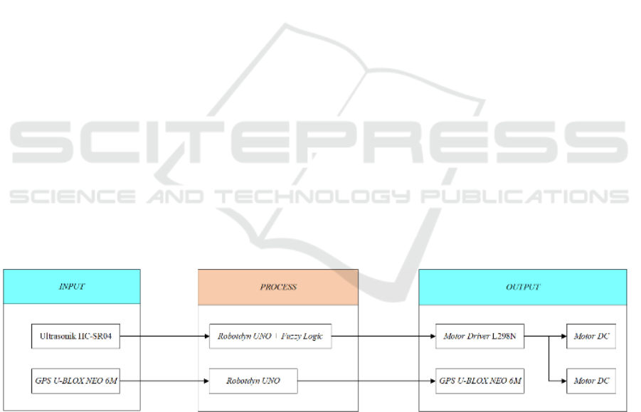
form of a simple prototype. The block diagram of
the Ground Vehicle movement control system
design system is shown in figure 3. The design of
the Ground Vehicle movement system consists of 4
actions that will be output when the Ground Vehicle
position with the obstacle is at a safe distance or 10
cm - 15 cm, which stops, goes forward, turns right,
and turns left. The design of the movement system
also consists of three main frameworks, namely,
input (input), process (process), and output (output).
The working method of this system itself is where
the input value given by ultrasonic in the form of
distance value to the obstacle will be forwarded to
the robotdyn UNO microcontroller which has been
integrated with fuzzy logic to be processed by the
applied coding, after that the data from robotdyn
Figure 3: Design System of Controller
UNO has been completed processed will be
forwarded to the output value, which will then give
an order to the motor driver to adjust the DC motor
rotation according to the results of the data that has
been given from the robotdyn UNO. This is different
from the process carried out by GPS where input
originating from the
signal transmission to the satellite will be sent back
to the GPS module which will then be processed by
the robotdyn UNO microcontroller with coding that
has been applied and clearly different from previous
coding (without fuzzy logic), after that the result of
the robotdyn UNO process will be forwarded back
to the GPS module as an output by providing a value
in the form of coordinate position or point of
location of the Ground Vehicle.
This design is the initial design carried out to
find out how the composition of each component
Design of Ground Vehicle System Semi-autonomous Preceder Type for Straight Path and Circular Path using Fuzzy Logic Method
179
that will be used is in accordance with the place or
not.
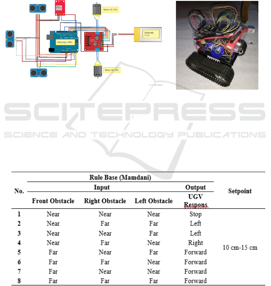
Ultrasonic Sensors are attached to the robotdyn
UNO with the trigger pin and echo pin configuration
inserted into the analog header pin. The continuous
track wheel used has 2 DC motors as the drive, and
the Motor Driver functions to adjust the speed and
speed of the DC motor. After that, the GPS module
will also be paired according to the analog header
pin specified in the robotdyn UNO separately
supplied by the 11.1 Volt 1000 mAh
LithiumPolymer (LiPo) battery power supply.
The hardware design that has been completed
will be adjusted again with the next coding, which
will be explained in the system design. The
hardware design is also included with the wiring
activity, as shown below
Figure 4: Ground Vehicle
4 RESULTS
The rule base of fuzzy logic is used to process input
values, which afterward will be output values as
commands in the form of decisions. This rule base
also has components in the form of certain
Variables which will then be used in the prototype
system. The variables needed to increase the
accuracy of the programming process are three
inputs named input values of the front direction,
values of the right side direction, and values of the
left side direction.
Table 1 Rule Base Fuzzy Logic Ground Vehicle
ICONIT 2019 - International Conference on Industrial Technology
180
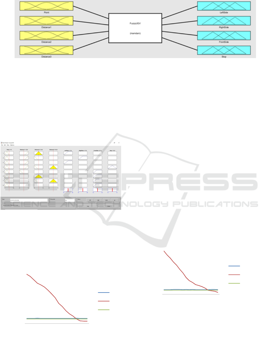
Figure 6: Fuzzy Inference System
The formation of a fuzzy inference system is
based on the input, output, and rule base that has
been determined and compiles it based on the
inference mechanism that has been selected, namely
Mamdani's inference mechanism.
Rule readings on the specified member function, as
in Figure 7, starting from the input, the process with
the inference mechanism to output if it is in
accordance with the design plan, the system can be
applied.
Figure 7: Fuzzy Inference System
The results of the first experimental data have
been reshaped into a graph that provides a clear
description of the results obtained, as shown in
Figure 8.
Figure 8: First Experiment Straight Path Without Obstacle
Data
The graph shown in Figure 8 can explain how
the fuzzy logic system performance is applied
directly based on the data obtained for the first
experiment. The X-axis on the graph shows the
distance between the Ground Vehicle and the
obstacle consisting of 3 sides, namely front, left, and
right, and the Y-axis on the graph showing the
amount of data recorded during the Ground Vehicle
functioning from the initial line to the finish line.
The data lines for the left and right directions do not
have a big difference because the values tend to be
the same, so the lines are also almost parallel, but
this is different from the frontline data, which has a
high initial position in the graph with a large initial
value. The value decreases and is almost parallel
with the other 2 data lines because the Ground
Vehicle position that is getting closer to the
destination point will produce a smaller distance
value with a maximum setpoint value of 10 cm from
the obstacle destination point.
For the second experiment, the graphs formed
based on data can be considered in Figure 9 as
follows:
Figure 9: Second Experiment Straight Path Without
Obstacle Data
In Figure 9 it can also be seen that the flow from
the left, front and right data lines has the same
concept as Figure 8 where the left and right data
lines have values that are not much different and
almost parallel, then for the front line data also has
0
0.5
1
1.5
2
2.5
1357911131517
Distance (m)
Sum of Data
Left
Front
Right
0
0.5
1
1.5
2
2.5
1357911131517
Distance (m)
Sum of Data
Left
Front
Right
Design of Ground Vehicle System Semi-autonomous Preceder Type for Straight Path and Circular Path using Fuzzy Logic Method
181

the large initial value continues to change becomes
smaller due to the reduced distance between the
Ground Vehicle and the obstacle destination point so
that the final value is almost parallel to the other 2
data lines.
For the third experiment in Figure 10, there is a
graph formed based on data which can be reviewed
as follows:
Figure 10: Third Experiment Straight Path Without
Obstacle Data
The graphic concept is shown in Figure 10 also
tends to be the same as the previous two graphs,
namely the data lines in the left and right directions
are almost parallel because the values held are not so
different while the front data line has a large initial
value due to the Ground Vehicle position with
obstacle destination point has a long-distance range
so that the more Ground Vehicle position with the
destination point, then the resulting value is also
getting smaller and smaller until the position of the
data line is almost parallel to the other 2 lines.
The value of the distance generated at the front
for this experiment has a value that tends to be
small, and the variations it has are quite large, with a
range of distances that are also small. The graph
formed can be reviewed in Figure 11 as follows:
Figure 11: First Experiment Circular Path Without
Obstacle Data
The results of the graph on the first trial circular
path without obstruction have conciseness different
from the graph in the previous experiment, which is
located at the position of the left sideline whose
value tends to be consistently large starting from the
initial position to the final position. The values on
the right side and the front side have the same
concept as the previous graph, which is almost
parallel because the values possessed by both have a
difference not so far away.
Then for the second experiment on the circular
path, there is a graph that has been formed, as shown
in Figure 12 as follows:
Figure 12: Second Experiment Circular Path Without
Obstacle Data
The concept in Figure 12 also has a form that
tends to be similar to the previous graph image; that
is, on the left side of the data line, it has a beginning
to end value that tends to be large when compared to
2 data on the right and front sides. The values on the
right and front side also have quite a lot of variations
with the characteristics of the value range that is also
small, but it is noted in the data on the right side that
there is a value below 10 cm which is 9 cm from the
obstacle wall arena. The cause is the same as in the
first trial circular path without obstruction.
Then for the third experiment on the circular
path, there is a graph that has been formed, as shown
in Figure 13 as follows:
Figure 13: Third Experiment Circular Path Without
Obstacle Data
0
0.5
1
1.5
2
2.5
1 3 5 7 9 11 13 15 17
Distance (m)
Sum of Data
Left
Front
Right
0
0.5
1
1.5
2
1357911131517
Distance (m)
Sum of Data
Left
Front
Right
0
0.5
1
1.5
2
1 3 5 7 9 11 13 15 17
Distance (m)
Sum of Data
Left
Front
Right
0
0.5
1
1.5
2
1357911131517
Ddistance (m)
Sum of Data
Left
Front
Right
ICONIT 2019 - International Conference on Industrial Technology
182

The graphical form in Figure 13 has a conceptual
basis, which tends to be the same as the two
previous trial graphs where the left side distance
value has a large value starting from the beginning
of the position to the end of the position. Data values
on the right and front also have values that vary with
a small range but tend to be consistent so that the
data lines shown are also almost parallel starting
from the initial position to the final position.
5 CONCLUSION
The conclusion of research of the fuzzy logic control
implemented in the UGV prototype is the control
system, and the objective was reasonably achieved.
The most important in this research is how to design
the control system using fuzzy logic. There is a lot
of variables that should be involved. However, this
research shows a starting point for more advanced
research on the topic similarly. Throughout this
research, the motion of UGV depends on DC motor
as an actuator, the robotdyn UNO microcontroller
based on the fuzzy logic rule base as the control
system and ultrasonic as a sensor to read the distance
between prototype and obstacle.
REFERENCES
Kiencke, U., 2001. Future perspectives of automotive
control. in Proc. 18th IEEE Instrumentation and
Measurement echnology Conf., Budapest. Hungary,
vol. 3, pp. 1510–1518.
Xiaolon, J., Zhibao, S., Xijun, Z., Gong, J., Yan, J., 2011.
Design of a Fuzzy PID Longitudilan Controller for
Autonomous Ground Vehicle. IEEE. pp.269-273.
Kim, H.W., Jung, S., 2013. Fuzzy Control for Balancing
of a Two-Wheel Transportation Robotic
Vehicle:Experiment Studies.IEEE.
Hirulkar, S., Damle, M., Rathee, V., Hardas, B., 2014.
Design of Aoutomatic Car Breaking System Using
Fuzzy Logic and PID Controller.International
Conference on Electronic Systems, Signal Processing
and Computing Technologies, pp. 413-418.
Franck, D., 2013, Introduction to Fuzzy Logic,
Massachusetts Institute of Technology, Cambridge.
Basjaruddin, NC., Kuspriyanto, Suhendar, Saefudin, D.,
Aziz, VA., 2016. Hardware Simulation of Automatic
Braking System Based on Fuzzy Logic Control.
Journal of Mechatronics, Electrical Power, and
Vehicular Technology. Vol.07, pp.1-6.
Pramudijanto, J., Ashfahani, A., Lukito, R., 2018,
Designing Neuro-Fuzzy Controller For
Electromagnetic Anti-Lock Braking System (ABS) On
Electric Vehicle, Journal of Physics.
Maghfiroh, H. et.al., 2016, Speed Control of a Single
Taipei Mass Rapid Transit System Train by Using a
Single Input Fuzzy Logic Controller, International
Journal of Electrical and Computer Engineering
(IJECE) Vol.6 No.2, pp.621-62
Design of Ground Vehicle System Semi-autonomous Preceder Type for Straight Path and Circular Path using Fuzzy Logic Method
183
