
A Solution to Increase Natuna D Alpha’s Resource Utilization by
Cryogenic Distillation: Conceptual Design & Sensitivity Study
Wijoyo Niti Daton, Ezra Revolin, Siptian Nugrahawan, Prasandi Abdul Aziz, Tutuka Ariadji, Steven
Chandra and J. A. Nainggolan
Petroleum Engineering Program, Institut Teknologi Bandung, Jalan Ganesha No 10 Bandung, Indonesia
Keywords:
Cryogenic Distillation, CO
2
Separation, CO
2
Transportation.
Abstract:
Natural gas extracted from its respective reservoir needs to be processed to meet the specifications of sales
gas. CO
2
is one of the components that needs to be separated from natural gas. The CO
2
concentration of
natural gas varies from a content of less than 20 mole % to more than 80 mole%. There is a problem when
the content of CO
2
is very high so it is necessary to modify the CO
2
level reduction by modifying the equip-
ment or changing the operating conditions to meet the desired CO
2
purity. In this study, field conditions and
characteristics reviewed is East Natuna Gas Field which has a gas composition of 71% CO
2
and 29% methane
with modified pressure based on the capability and capacity of available equipment. From the conditions and
characteristics of the field, the CO
2
method of separation from natural gas using cryogenic distillation was
chosen.This research presents analysis and sensitivity of technical parameters that influence the method of
CO
2
separation from natural gas using cryogenic distillation. The sensitivity is done by changing parameters
of pressure and very high feed gas flow rate into the column. In addition, the calculation of the diameter and
height of the distillation column using the calculation of the formula and the results of the simulation using
commercial process flow software. This study applies a CO
2
separation process with cryogenic distillation
and the desired product specification of CH
4
is 99%. The design of the equipment was simulated using two
distillation columns with operating pressure at the first distillation column of 45 bar and the temperature of
19.19 oF, and for the second distillation column the operating pressure was reduced to 35 bar. The results are
for the 8000 MMSCFD flow rate case obtained the first number of columns as many as 16 with the size of
7.4 meters diameter and 17.66 meters high, while the number of second column of 4 with the size of 8 meters
diameter and 22.38 meters high. The results presented are still less suitable with the conditions in the East
Natuna Gas Field because offshore constrains so need to be studied further for design and other methods in
application in the field.
1 INTRODUCTION
Natural gas is one of most the important energy
sources in the world. Today humans use natural gas
to meet energy needs, where the use of gas is esti-
mated to increase by 1.5% each year (IEA, 2017).
Global gas demand for natural gas increased from
3635 bcm in 2016 to more than 5300 bcm in 2040
(IEA, 2017) Indonesia is one of the archipelagic coun-
tries that has large gas reserves spread across sev-
eral regions, one of which is the East Natuna Block.
Natuna Timur block is one of the gas fields that has an
abundant source of gas reserves, which makes Natuna
the largest undeveloped gas reserve in Southeast Asia
(Fenter et al., 1996). However, the abundant potential
of gas reserves also has a very high CO
2
gas content
so that CO
2
separation technology is needed so that
the gas produced can be utilized properly. Impuri-
ties such as CO
2
, H2S, and other acid gases need to
be removed from natural gas because in the presence
of water, this content can make pipes and other tools
corroded(Rufford et al., 2012).
At present, various methods of acquisition and
technology have been implemented to increase nat-
ural gas production. The existing technology is ad-
justed to the field conditions and characteristics. One
challenge that is often faced is the presence of acid
gas contained in it. Sources of acid gas are natural
gas resources that contain most of CO
2
and/ or H2S
(Burgers et al., 2011). The separation process can be
designed to overcome differences in molecular prop-
erties or thermodynamic properties and the .
342
Daton, W., Revolin, E., Nugrahawan, S., Aziz, P., Ariadji, T., Chandra, S. and Nainggolan, J.
A Solution to Increase Natuna D Alpha’s Resource Utilization by Cryogenic Distillation: Conceptual Design Sensitivity Study.
DOI: 10.5220/0009427203420348
In Proceedings of the Second International Conference on Science, Engineering and Technology (ICoSET 2019), pages 342-348
ISBN: 978-989-758-463-3
Copyright
c
2020 by SCITEPRESS – Science and Technology Publications, Lda. All rights reserved
displacement of components in the mixture (Ruf-
ford et al., 2012). Therefore several methods of sepa-
ration of acid gas have been developed, or commonly
called sweetening gas processes for H2S separation,
such as absorption, adsorption, membrane and cryo-
genic methods, each of which is used for different
properties and conditions of fluid and field. In this
study, the selection of CO
2
separation method with
reference characteristics from the East Natuna Gas
Field was carried out and a process simulation was
carried out to obtain the results of the high CO
2
con-
tent separation by observing the effect of pressure and
the feed rate from CO
2
gas was very high.
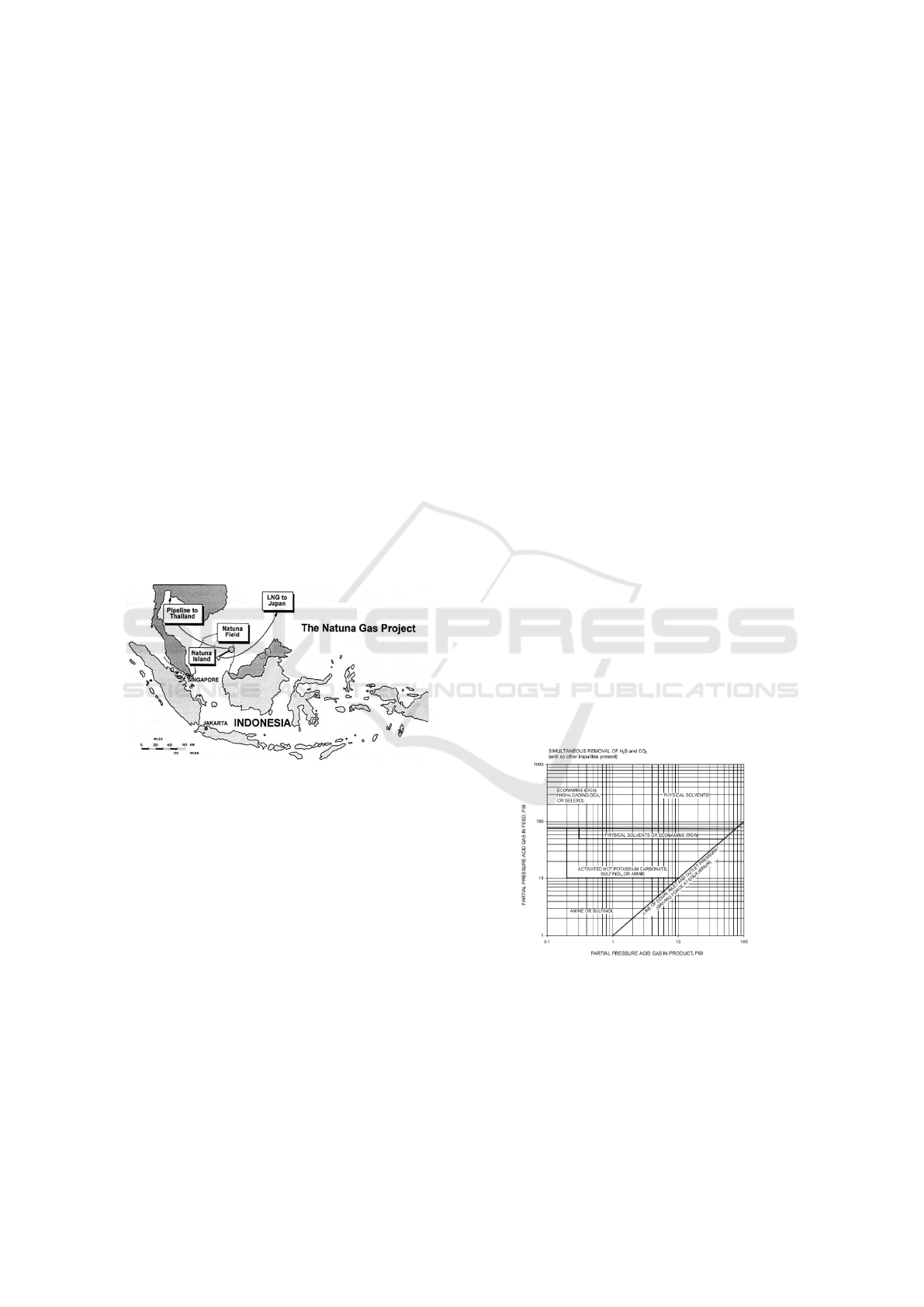
Natuna Gas Field is located in Indonesian waters
precisely in the Natuna Sea. This field is 140 miles
northeast of the Natuna Islands and 218 miles north-
west of the island of Borneo. The water depth of this
field is around 475 feet. The amount of gas volume
in the reservoir is estimated at 222 TSCF with the
composition of the gas contained among others 71%
CO
2
, 28% methane and heavy diffraction hydrocar-
bons, 0.5% H2S, and 0.5% N2 (Fenter et al., 1996).
The Natuna Gas Location Map is shown in Figure 1.
Figure 1: Location of Natuna Field (Fenter et al, 1996).
Natuna gas reservoir is interpreted in the form of
carbonate domes which are isolated and contained in
the Miocene Reef Formation (Fenter et al., 1996). If
the formation is a carbonate formation, calcite disso-
lution will form CO
2
. The high CO
2
content in the
Natuna gas reservoir is estimated to be the result of
the calcite dissolution process (Suarsana et al., 2010).
This reservoir has a pressure of 5717 psig and a tem-
perature of 340 F which is measured by measuring
the well at the central depth. The estimated gas yield
from this field is 75% with recoverable hydrocarbon
gas of 46 TSCF (Fenter et al., 1996).
Natuna Field Reservoir contains more CO
2
than
hydrocarbons. CO
2
dominates the aging of the reser-
voir phase and controls the production method. Be-
cause this reservoir fluid contains more hydrocar-
bon components, this reservoir is considered a non-
hydrocarbon reservoir (Suarsana et al., 2010).
2 OVERVIEW OF NATURAL
GAS-CO
2
SEPARATION
PROCESS
During the requirement of separating CO
2
from nat-
ural gas, not all available methods can be applied in
every field. Considerations of methods available on
separating high levels of CO
2
is important so that the
selection of the right method will give good results.
In addition, differences also depend on the thermody-
namic and transport properties (interphase), in which
case the properties considered include vapor pressure,
boiling point, solubility, adsorption capacity, and dif-
fusivity (Rufford et al., 2012). Based on the nature
of the components to be separated, the main opera-
tion in the gas separation and purification mechanism
follows the mechanism: (1) phase formation by heat
transfer and / or shaft work into or from the mixture,
(2) absorption on liquid sorbents or solids, (3) adsorp-
tion on solids, (4) permeation through a membrane,
and (5) changes in chemical compounds into other
compounds (Kohl and Nielsen, 1997)(Seader et al.,
1998). The direct chemical change in CO
2
which is
currently under study is an example of dry reforming
process, namely CO
2
reacts with CH
4
to form syn-
gas (mixture of H2 and CO
2
) which can later be used
to produce liquid fuel through a Fischer-Tropsch re-
action (Rufford et al., 2012) Then the selection for
selecting an acid gas treating process can be viewed
from the gas partial pressure, based on references
from Aden (Nexant, 2011) and shown in Figure 2.
Figure 2: CO
2
Removal Chart Based on Partial Pressure
(Aden, 2009).
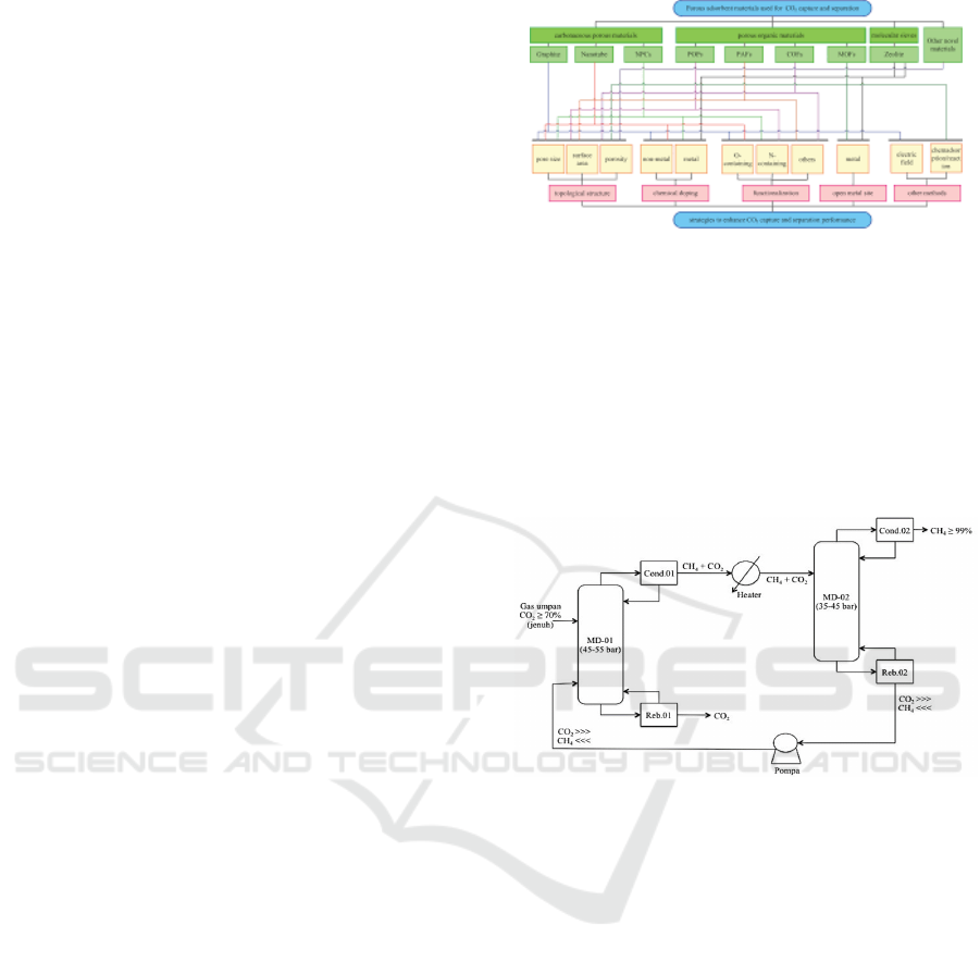
Based on the results of Revolin’s (2016) research,
the selection of the CO
2
method can be done with
the help of the separation process selection diagram
shown in Figure 10. In addition, in this thesis a selec-
tion of CO
2
separation methods was carried out with
references from (Rufford et al., 2012) based on sev-
A Solution to Increase Natuna D Alpha’s Resource Utilization by Cryogenic Distillation: Conceptual Design Sensitivity Study
343
eral influential parameters in Table 1. In this study, the
factors that were considered to be the most influential
in the process of selecting CO
2
separation methods
from natural gas include:
• The presence or absence of H
2
S gas content
• Concentration of feed gas CO
2
• Feed gas flow rate
• The purity of CH
4
and CO
2
products
From the Natuna Field case, there are several
characteristics that are owned as consideration of the
choice of methods including:
• The H
2
S content is small
• The concentration of the gas content is 29%
methane and 71% CO
2
• Flow rate is very high (more than 1 BSCF, de-
pending on the duration of the contract)
• The desired purity of the product is at least 95%
methane, in this case it is targeted to be 99%.
From the parameters of CO
2
inlet concentration
above 50%, then based on a summary of the techno-
logical characteristics in Table 1 that may be used are
membrane technology, absorption with amine, and
cryogenic distillation. Then the selection process is
also carried out with the help of a selection diagram
in Figure 3 with the results of technology suitable for
use, namely cryogenic absorption and distillation. In
this study, membrane technology and absorption were
not chosen because there were several considerations
based on (Rufford et al., 2012). Membrane technol-
ogy requires pretreatment processes to remove heavy
liquids or hydrocarbons because it can cause damage
to membranes and blockages. Membrane quality de-
pends on permeability and selectivity that cannot be
obtained simultaneously. In addition, membranes are
sensitive to feed conditions and hydrocarbon loss is
also higher than other technologies. In the absorption
method another unit is needed to regenerate solvents
in the process of CO
2
gas separation. In this method
it is also often formed loading, foaming, and channel-
ing so that mass transfer is not good. Then, the ab-
sorption method requires a large amount of solvents
to separate the volume of high CO
2
gas, which makes
energy consumption also higher especially for regen-
erating solvents. Conformity between the character-
istics of the cases and categories in this study resulted
in the selection of cryogenic distillation.
In this study the simulation of CO
2
separation us-
ing the cryogenic distillation method was carried out
using the Aspen Hysys V10 software. Simulation
of CO
2
separation was carried out by applying refer-
ence to the cryogenic distillation process by Pellegrini
Figure 3: CO
2
Separation Guideline (Liu et al., 2015).
(Pellegrini et al., 2015) with simplification of one dis-
tillation column and reference from Revolin (2016) as
a simulation baseline with several assumptions used
in the process including simplified feed gas compo-
nents in the form of binary mixture namely CO
2
and
methane, and the vapor and liquid phases are consid-
ered ideal. The scheme of the distillation process can
be seen in Figure 4.
Figure 4: Cryogenic CO
2
Separation (Pellegrini et al.,
2015).
In this CO
2
separation simulation the most im-
portant component observed is the distillation col-
umn. The distillation design process consists of de-
signing processes and mechanical design. Simulation
with shortcut distillation is used in the design pro-
cess to find out the mass balance and the variables
needed. Then, some parameters generated from this
simulation that are needed for mechanical design in-
clude pressure and temperature on the top product (in
the condenser) and the bottom product (in reboiler)
needed, the minimum and actual stage number, the
position of the feed gas stage, and reflux ratio early. In
this stage data on composition, pressure, temperature,
and feed gas flow rate are needed, as well as the speci-
fications of the condenser output and reboiler needed.
The feed gas flow rate obtained also makes the flow
rate data for each component in the feed known.
In mechanical design, rigorous methods are used
(with the distillation column) for more detailed and
detailed simulations to determine and determine the
profile of pressure and temperature in each stage, con-
ICoSET 2019 - The Second International Conference on Science, Engineering and Technology
344
denser and reboiler condition profiles, and the com-
position of CO
2
and methane from separation. It is
necessary to know the variables needed in the distilla-
tion column, including the composition and flow rate
of the feed gas, the pressure and temperature of the
feed gas, the position of the feed gas stage, the num-
ber of stages and the pressure profile, and the spec-
ifications of the desired product or product. Some
of the assumptions used in the distillation column
include each plate in the column having an equilib-
rium with constant pressure reduction with a rule of
thumb of 0.2 psi per plate. The pressure and tem-
perature of the feed gas entering the distillation col-
umn need to be adjusted to match the column op-
erating conditions. The high CO
2
content is cooled
to a certain temperature and pressure on the distilla-
tion column so that the CO
2
concentration decreases
to the desired level, which increases the concentra-
tion of methane. Pressure and temperature specifi-
cations are important factors that influence gas sep-
aration(Suarsana et al., 2010). The column operating
conditions are assumed to be in ideal conditions or in
the sense that the amount of feed gas to the distillation
column is equal to the number that exits the column.
Then the separation simulation is carried out using
two stages of design with several sensitivity studies
that refer to a predetermined base case condition.
From the base case that has been determined, pres-
sure sensitivity and the rate of gas feed production are
carried out into the distillation column. After a simu-
lation and sensitivity study, the reflux ratio results and
the number of stages needed to obtain the desired cri-
teria for the methane and CO
2
content are obtained.
Variations in the condition of the feed gas are carried
out with the condition of the condenser and the re-
boiler being fixed.
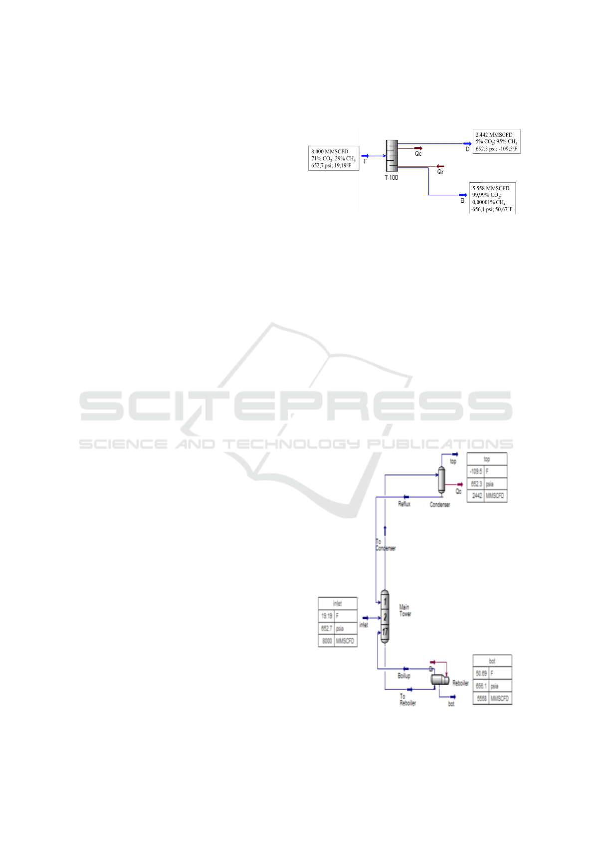
3 CASE STUDY
Before the sensitivity study, a base case was sim-
ulated with a composition of 71% CO
2
and 29% CH
4
, feed gas flow rate of 8 BSCFD, pressure of 652.7
psia, and temperature of 19.19 oF (at the dew point
point) with the result specifications in the CH
4
con-
denser with purity of ≥ 95% and the result of reboiler
CH
4
≤ 0.001%. From the variable reference shortcut
distillation method obtained, the minimum number of
stages required is 9,643 with rounded up to 10 stages,
the actual number of stages is 17, and the feed gas
flow is optimal in the second stage. Then the results
of the condenser namely CH
4
composition has a flow
rate of 2,442 BSCFD and from the reboiler obtained
a flow rate of 5,558 BSCFD. The shortcut distillation
operation scheme in the base case can be seen in Fig-
ure 5.
Figure 5: Cryogenic CO
2
Separation (Pellegrini, 2014).
The results of the number of stages and reflux ra-
tios obtained from the shortcut distillation simulation
are entered into the distillation column for rigorous
distillation simulation and the results for this base
case condition are reflux ratios of 12.08. Comparison
of reflux ratio calculations with the shortcut distilla-
tion method and rigorous distillation gives different
values. This is due to the rigorous distillation simula-
tion, the calculation is done in more detail and detail
that considers many variables and results until the de-
sign of column sizes. The results obtained are in the
form of a static plant simulation and even dynamic
if added to the addition of controls (Biyanto, 2007).
While the distillation shortcut is still a rough calcula-
tion or not done in detail. The CO
2
separation scheme
uses rigorous distillation in the base case distillation
column attached to Figure 6.
Figure 6: Cryogenic CO
2
Separation (Pellegrini, 2014).
A Solution to Increase Natuna D Alpha’s Resource Utilization by Cryogenic Distillation: Conceptual Design Sensitivity Study
345
Then a sensitivity study is carried out by review-
ing the variable pressure and feed gas flow rate. The
temperature conditions of the feed gas, gas specifica-
tions produced, and variations in flow rates are made
the same in each case. The feed gas flow rate and
the flow rate of the separation results for each rate are
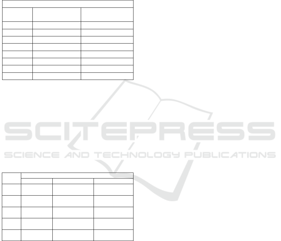
shown in Table 1.
Table 1: Gas Flow Rate on Distillation Column.
Flow Rate (MMSCFD)
Feed Gas Condenser (Top) Reboiler (Bottom)
8000 2442 5558
1000 305.2 694.8
2000 610.4 1389.6
3000 915.6 2084.4
4000 1221 2779
5000 1526 3474
6000 1831 4169
7000 2136 4864
From Table 2, the flow rate of CH
4
generated
from the condenser is smaller than the flow rate of
CO
2
generated from the reboiler because the fraction
of the CO
2
component in the feed gas is greater than
CH
4
. And also in this study, the calculation in the
simulation uses the assumption of a 100% efficiency
level in the separation process so that the total flow of
the feed gas entering is equal to the amount that comes
out. The following are the operating conditions of the
distillation tower for each case shown in Table 2.
Table 2: Gas Condition in Distillation Column.
Case
Operating Condition
Feed Gas Condenser Reboiler
Base
P = 652.7 psi
T =19.19 F
Pcond = 652.3 psi
Tcond = -109.5 F
Preb = 656.1 psi
Treb = 50.67 F
Case 1
P = 507.6 psi
T =19.19 F
Pcond = 507.2 psi
Tcond =-120.9 F
Preb = 510.2 psi
Treb = 33.3 F
Case 2
P = 362.6 psi
T =19.19 F
Pcond = 362.4 psi
Tcond = -130.1 F
Preb = 364.6 psi
Treb = 33.3 F
Case 3
P = 217.6 psi
T =19.19 F
Pcond = 217.4 psi
Tcond =-140 F
Preb = 219.4 psi
Treb = -17.5 F
Case 4
P = 72.52 psi
T =19.19 F
Pcond = 217.4 psi
Tcond = -163.3 F
Preb = 73.92 psi
Treb = -69.13 psi
In terms of operating conditions, the pressure on
the condenser needs to be made smaller than the re-
boiler pressure. This is so that the steam formed can
rise to the top of the column, according to the prin-
ciple of fluid flow that the gas will flow from high
pressure to low pressure.
From the sensitivity results obtained that the
greater the pressure of the feed gas into the distilla-
tion column, with the same flow rate and tempera-
ture of the feed gas, the more reflux ratio is needed.
This is because with high pressure the more steam
formed. Even though the reflux system is condens-
ing steam, so if the steam is high then the reflux ra-
tio is also high. This applies also with the increasing
pressure of the feed gas, the greater the number of
stages needed. The principle of the stage is to sep-
arate the components in the gas feed, if the pressure
is high then the interaction of the gas component is
also higher, then more stages will be needed for the
separation process. In this study the magnitude of the
feed gas flow rate does not directly affect the magni-
tude of the relux ratio and the number of stages. For
each case carried out, the value of reflux ratio and the
number of stages are the same, but the magnitude of
the feed gas flow rate affects the diameter of the dis-
tillation column more and the energy needed, in this
case the condenser duty and reboiler duty. The greater
the feed gas flow rate, the greater the dimension (di-
ameter and height) of the distillation column and the
energy needed. This is because a large flow rate re-
quires a large capacity.
After the sensitivity to the influential parameters
it was found that in distillation using distillation is
strongly influenced by pressure and rate feed gas flow.
The smaller the condenser duty feed gas pressure and
the reboiler duty is also greater, but it needs to be ad-
justed again with the existing capacity. In the low
temperature process carried out on the separation of
the natural gas flow with high CO
2
concentration the
cooling cycle is required in the process. In this condi-
tion, electrical energy needs are one of the important
factors because they are needed in the cooling cycle.
Therefore it would be better to choose the lowest pres-
sure energy conditions, especially in this study the
condenser and reboiler. From the results of the sensi-
tivity obtained the selection of pressure is taken at the
greatest value. In this study the pressure was in the
range of 5-45 bars. In this study cryogenic distillation
was not carried out by a higher pressure review be-
cause of the limitation of temperature determination
of 19.20 F and the feed gas vapor fraction 1 which
could be achieved with higher pressure when the tem-
perature was also raised. Therefore it was chosen, the
feed gas pressure was 45 bar in this study.
The design of the CO
2
separation process in this
study used the method in the Pellegrini (Pellegrini
et al., 2015) patent with separation using two distil-
lation columns. The feed gas pressure entering in the
first column is 45 bar and in the second column 35
bar. The purity results obtained in this study were
99% CH
4
at the end of the second column. From the
first column to the second column a heater and valve
are given to reduce pressure. Then the output of CO
2
in the second column is pumped back to the first col-
umn for re-separation. The design of this process can
ICoSET 2019 - The Second International Conference on Science, Engineering and Technology
346
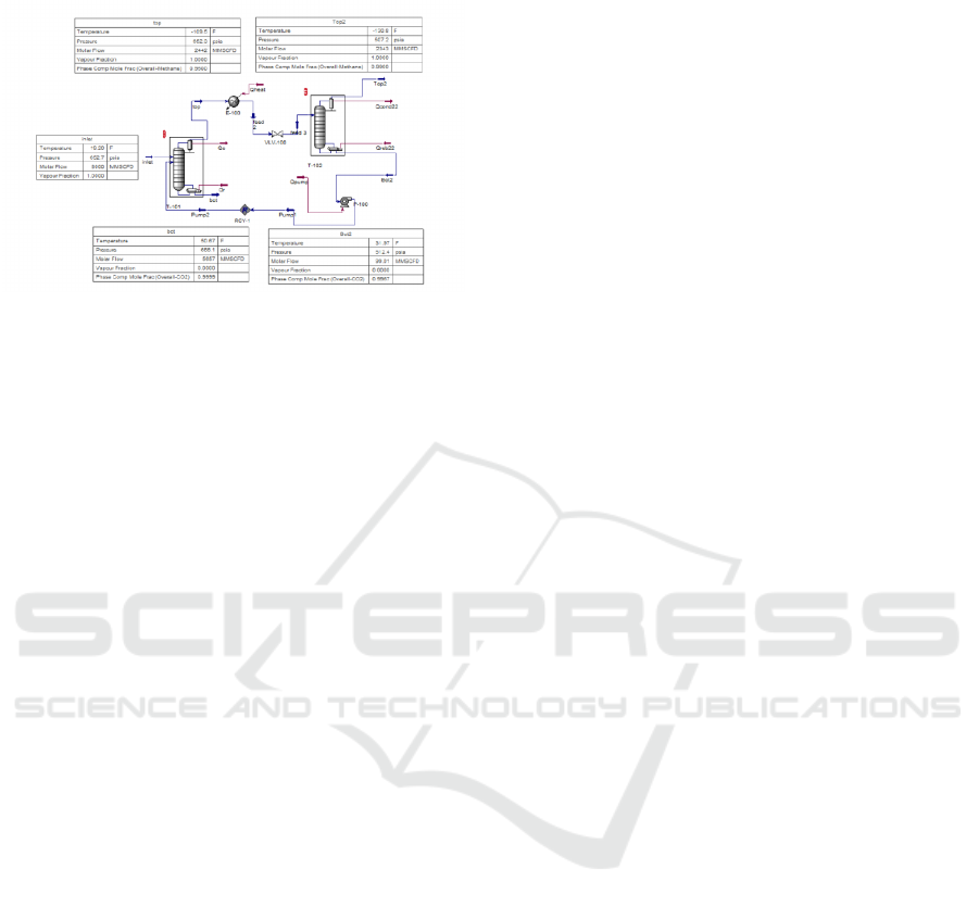
be seen in Figure 7.
Figure 7: Overall Design of Cryogenic Process.
To validate the results of the calculation of the dis-
tillation column, a reference is needed for compari-
son. In this study a reference to the size of the dis-
tillation column from the RCC Regenerator Column
was used, Balongan refinery with a diameter of about
9 meters and a height of more than 20 meters. Then
the feed gas rate is determined by the length of the
agreed contract. In this study the reference of feed
gas flow rate uses a reference from Nainggolan (2016)
with a flow rate of 8 BSCFD. From these references,
determining the size of the distillation column can be
done.
The variation in flow rate from 1-8 BSCFD pro-
duces a diameter of more than 11 meters. Whereas
the flow rate of 100-800 MMSCFD has the largest di-
ameter at the rate of 800 MMSCFD with a value of
10 meters. For the rate of 8 BSCFD, a diameter of
52.5 meters is produced, in the field this condition is
not possible so there is a need for a scenario to di-
vide the flow rate in the column in parallel, more than
one in each column. In the first column the maximum
rate that can be accommodated is 500 MMSCFD with
a diameter of 7.4 meters, while for the second col-
umn the maximum rate that can be accommodated is
610.4 MMSCFD from the results of the first column
with a diameter of 8 meters. The scenario is based
on the smallest condenser duty and reboiler duty to-
tal requirements is selected so that the first scenario
with column 1 (7.4 meters in diameter and 17.66 me-
ters in height) is obtained and 16 pieces are needed
column 2 (with a diameter of 8 meters and a height
of 22.38 meters) requires 4 pieces. From these results
for the next process, it is necessary to consider the ap-
plication of the distillation column in the field, with
the limitation of the location of the Natuna Gas Field
which is offshore resulting in the availability of land
and installation of the distillation column equipment
that needs to be reviewed.
Based on the designs presented above, it can be
proposed to be two main distribution/processing hub,
namely the platform based unit processing and on-
shore facility, connected with underwater pipeline. It
is worth noting that applying platform based process-
ing facility requires massive capital due to the size
of the processing facility, while using onshore facil-
ity would require very large pipe with high corrosion
potential. Further study should be done to assess the
economic and technical feasibility of these projects.
4 CONCLUSIONS
The choice of CO
2
separation technology from natu-
ral gas is based on several factors that are highly de-
pendent on the conditions and characteristics of the
gas field being reviewed.
Under pressure and gas flow rates based on the
case of the Natuna Gas Field, the cryogenic distilla-
tion process is chosen in the separation of CO
2
con-
tent at high flow rates, and is considered capable of
obtaining specifications of CO
2
content of less than
or equal to 1%.
In designing CO
2
separation using cryogenic dis-
tillation at a very high flow rate, a flow rate distri-
bution scenario in parallel with different columns is
needed to meet these needs due to limited location
availability.
With the content of 71% CO
2
and 29% methane,
the results of separation using two-column cryogenic
distillation obtained by the case of 8000 MMSCFD
flow rate obtained the number of the first column as
much as 16 with a diameter of 7.4 meters and height
of 17.66 meters, while the number of second columns
was 4 in diameter 8 meters high and 22.38 meters.
REFERENCES
Biyanto, T. R. (2007). Cascade control using soft sensor for
aldehide column energy saving. IPTEK The Journal
for Technology and Science, 18(4).
Burgers, W., Northrop, P., Kheshgi, H., and Valencia, J.
(2011). Worldwide development potential for sour
gas. Energy Procedia, 4:2178–2184.
Fenter, D., Hadiatno, D., et al. (1996). Reservoir simulation
modeling of natuna gas field for reservoir evaluation
and development planning. In SPE Asia Pacific Oil
and Gas Conference. Society of Petroleum Engineers.
IEA (2017). WEO 2017.
Kohl, A. L. and Nielsen, R. (1997). Gas purification. Else-
vier.
Liu, X., Jin, D., Wei, S., Wang, Z., An, C. G., and W.
(2015). Strategies to enhance CO2 capture and sepa-
A Solution to Increase Natuna D Alpha’s Resource Utilization by Cryogenic Distillation: Conceptual Design Sensitivity Study
347

ration based on engineering absorbent materials. Jour-
nal of Materials Chemistry A. 3, 3.:12118–12132.
Nexant, Inc., S. F. C. (2011). Survey and Down-Selection
of Acid Gas Removal Systems for the Thermo-
chemical Conversion of Biomass to Ethanol with a
Detailed Analysis of an MDEA System. Techni-
cal report, National Renewable Energy Laboratory
(NREL), Golden, CO (United States).
Pellegrini, L. A., Oldrich, M., Lange, S., and Picutti, B.
(2015). A New Cryogenic Technology for Natural Gas
Sweetening. Presented at SOGAT 2015, Abu Dhabi.
Rufford, T. E., Smart, S., Watson, G. C., Graham, B.,
Boxall, J., Da Costa, J. D., and May, E. (2012).
The removal of co2 and n2 from natural gas: A re-
view of conventional and emerging process technolo-
gies. Journal of Petroleum Science and Engineering,
94:123–154.
Seader, J. D., Henley, E. J., and Roper, D. K. (1998). Sepa-
ration process principles.
Suarsana, I. P. et al. (2010). Producing high co2 gas content
reservoirs in pertamina indonesia using multi stage
cryogenic process. In SPE Asia Pacific Oil and Gas
Conference and Exhibition. Society of Petroleum En-
gineers.
ICoSET 2019 - The Second International Conference on Science, Engineering and Technology
348
