
Analysis of Turbine Round Effect with the Voltage Generated in
Micro Hydroelectric Power Prototype
Ain Sahara, Frederikus Aly, Riza Hadi Saputra, Meita Rezki Vegatama
Sekolat Tinggi Teknologi Minyak dan Gas Bumi Balikpapan, East Borneo, Indonesia
Keywords: Prototype, Micro-Hydro, Turbine, Voltage
Abstract: In connection with the high demand for energy in remote and rural areas, one way to meet these needs is to
make micro hydro-based electricity. Microhydro electrical energy is very suitable for use in rural areas
because the area is usually found in many sources of waterfalls that can be used as a source of micro-
hydropower without causing environmental damage. In this case, the author made a prototype of micro-hydro
power to be able to analyze the effect of rotation of the turbine with the voltage generated, before it will be
implemented. The faster the generator rotates, the greater the voltage caused by the rotor cutting the line
magnet force on the stator coil so that the resulting voltage will be faster too. In testing the maximum 6V
results in the 1200 RPM turbine rotation, it can be said that the results obtained are only half of the generator's
work, due to the water pressure that does not affect the turbine rotational motion.
1 INTRODUCTION
New and renewable energy sources in the future will
increasingly require a very important role in meeting
energy needs. This is caused by the use of fossil fuels
for conventional power plants, which in the long run,
will deplete the source of petroleum, gas, and coal
whose reserves are increasingly depleting. The
National Electricity Company (PT. PLN) as an
energy-producing industry also uses fuel (fuel oil) to
turn large generator engines. Natural resources are
non-renewable; what can be needed requires a long
time (Reharmanto, 2007). Therefore, alternative
energy is needed to overcome this. That can be
realized with the increasingly developing technology.
Therefore, there is alternative energy that can be used
to replace fossil fuels, such as sunlight, geothermal,
wind, air, and coal (Yogo Pratisto, 2014). Alternative
energy like this, which is expected to replace the
fossil fuels used so far to be converted into electrical
energy, replaces the reserves of fossil fuels that we
will get (Liun, 2011). The author will choose a micro-
hydropower plant, and a micro-hydropower plant is a
power plant that uses air power, which is one
alternative energy that uses air power.
2 BASIC THEORY
2.1 Hydroelectric Power Generation
Hydroelectric power generation is a generation of
electrical energy by converting the potential energy
of water into mechanical energy by a turbine, which
then converted into electrical energy by a generator
by utilizing the height and speed of water flow
(Pranata, 2014). There are several types of
hydroelectric power plants, including:
a. Hydropower type waterway
b. Hydropower DAM/DAM type
c. Hydropower with regulatory pond
d. Hydropower type pumped storage
2.2 Water Turbine
Water turbines are tools for converting potential
energy from water mechanical energy. The
mechanical energy is then converted into electrical
energy by a generator. With the advancement of fluid
mechanics and hydraulics, as well as paying attention
to the abundant sources of water energy available in
rural areas, the plan for turbine emerges which varies
with the high fall of water (head) and available water
discharge (Q) (Haimerl L.A, 1960).
124
Sahara, A., Aly, F., Saputra, R. and Vegatama, M.
Analysis of Turbine Round Effect with the Voltage Generated in Micro Hydroelectric Power Prototype.
DOI: 10.5220/0009423501240128
In Proceedings of the 1st International Conference on Industrial Technology (ICONIT 2019), pages 124-128
ISBN: 978-989-758-434-3
Copyright
c
2020 by SCITEPRESS – Science and Technology Publications, Lda. All rights reserved

2.3 Generator
The generator is a device that can convert mechanical
energy into mechanical energy. Mechanical power
can be gained from heat, water, and steam. The
electrical energy produced by a generator can be
either AC (alternating electricity) or DC (direct
electricity). This depends on the construction of the
generator used by the power plant. The generator is
closely related to faraday law. The following are the
results of the legal faraday "that if a piece of the
electrically conductive wire is in a changing magnetic
field, then an electric force will form in the wire."
If a long metal is in an electric field, it will cause the
free electron to move to the left, which will eventually
cause an induced electric field that is as strong as the
electric field so that the total field strength becomes
0. In this case, the potential of the two metal ends
becomes equal, and the electron's flow will stop. As a
result, both ends of the metal have an induction
charge. For the free electron flow to continue, the
induction charge must continue to be taken, so that
the induced electric field does not arise on the metal.
Furthermore, the source of electromotive force (emf)
in the form of a battery can make the potential
difference between the two ends of the price remain
fixed so that the electron flow continues.
There are two types of electric generators:
a) AC generator (alternating current)
b) DC generator (direct current)
AC generators produce alternating electric current
because of the current direction will be reversed at
every half turn. DC generators produce direct current
of electricity because the construction is equipped
with a commutator, usually functions as an amplifier
in the main generator induced.
2.4 Arduino
Arduino is an open-source single-board
microcontroller, derived from the wiring platform,
designed to facilitate electronic use in various fields
(Santoso, 2015). The hardware has an Atmel AVR
processor, and the software has its programming
language. Arduino is a versatile microcontroller kit
that is very easy to use. To make it needed a
programmer chip (to embed the Arduino bootloader
on the chip). Both Arduino's hardware and software
are available from open sources. On the side of
software, Arduino can be run on various platforms,
namely Linux, Windows, or also Mac. Arduino
hardware is a microcontroller based on AVR from
ATMEL, which has been given a bootloader and also
has standard I / O pins.
2.5 Voltage Sensor
The voltage sensor functions to read the voltage value
of a circuit. Arduino can read the voltage value using
an analog pin. If the voltage range that is read
between 0-5 V, it can directly use an analog pin,
whereas if the voltage range is above 5V, we must use
an additional circuit voltage divider. This is due to
circumstances that the Arduino pin works at max 5 V.
2.6 RPM Sensor
The RPM sensor is a sensor that serves to read how
many rotating objects are rotating, such as the wheel
rotation, turbine rotation of gear rotation. The
common principle of this sensor is to calculate the
speed of magnetic pulses or the principle of using
light as in an RPM sensor that uses an optocoupler
consisting of LEDs and phototransistors where the
phototransistor captures the speed of light from LEDs
to be converted as RPM sensors (Winanti, 2014).
3 METHODOLOGY AND
ANALYSIS
In this research report, there are research flow
diagrams, workflow diagrams, and tool block
diagrams that are intended to make it easier for
readers to understand the flow of starting data
collection and also how the stages of this tool work.
3.1 Flow Chart of The Tool Design
The following is a working flow chart of the tool
designed in Figure 1.
From the flow chart above can be explained the
working principle of the tool as follows:
a. Fill the reservoir with water,
b. Turn on the monitor/LCD first,
c. Water will move the turbine so that the turbine
will rotate, and the turbine rotation will drive
the generator so that the generator produces
electricity voltage.
d. The sensor will read how many voltages and turns
produced by the tool. There are two
possibilities:
- "Yes": The sensor volt will read how much voltage
is generated from the generator, then the RPM
sensor will read how many turns are produced
by the turbine
- "No ": step back on the monitor/LCD while
checking the problems that occur in the device.
Analysis of Turbine Round Effect with the Voltage Generated in Micro Hydroelectric Power Prototype
125
e. The result of the voltage read by the sensor volt
and the rotation generated by the turbine read
by the RPM sensor will be displayed on the
LCD.
No
Start
Putwaterintotheshelter
Turnonthemonitor
Turnonthewaterpump
Turbinesandgenerators
move
Sensorreadings
Outputisdisplayedon
theLCD
Finish
Yes
Figure 1. Flowchart of The Tool Design
3.2 Block Diagram of the Tool
The following is a block diagram of the tool created:
PompaAir Turbin
Sensor
Volt
Generator
Power
Supply
SensorRPM
Arduino LCD
OUT
Figure 2. Block Diagram of The Tool
From the block diagram above, it can be explained
the workflow component of the tool as follows:
a. When the power supply is connected, it will run
the water pump, and the LCD will turn on.
b. The water pump will work so that it spills water
to turn the turbine
c. When the turbine rotates, the turbine rotation
will be connected to the generator using a belt so that
the generator will spin too
d. The generator will spin so that it produces
voltage. The voltage that comes out will be read by
the voltage sensor, and the turbine rotation will be
read by the RPM sensor that uses a magnetic sensor
e. The results of the two sensors will be sent to
Arduino/microcontroller for later
f. The results of the data from Arduino/
microcontroller will be displayed on the LCD so that
we can find out the output voltage and how many
RPM the turbine rotates.
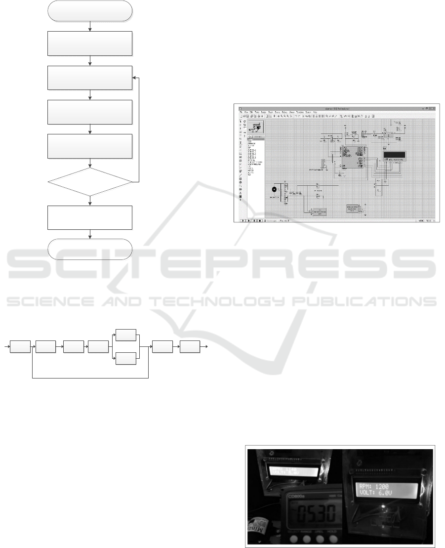
3.3 Design Hardware
The hardware design in this tool can be seen in the
schematic circuit of the microcontroller. In this series,
we can see how the schematic electronic circuits are
arranged, as shown in Figure 3 as follows:
Figure 3. Schematic Tool Set
In this schematic, it can be seen that the turbine
rotation is read by the RPM sensor that uses a
magnetic sensor, as in Figure 3. The reading results
then will be read by the microcontroller itself.
Afterward, in the rotating valve of the turbine will be
displayed on the LCD. The turbine rotation
magnitude is calculated by how many times the
magnet passes through the sensor. Then for the
voltage reading itself, it is read by a voltage sensor
where the voltage sensor will read what voltage is
generated from the generator, for the voltage
generated from the generator is an alternating voltage
(AC) then rectified by a rectifier (DC). After that, the
data will be brought to the microcontroller to be
converted into numbers and displayed on the LCD.
Figure 5. Results of Testing Tools
ICONIT 2019 - International Conference on Industrial Technology
126

Figure 6. The Prototype of Micro Hydro Power Plant
Tools
3.4 Software Program
The software used in this tool uses the CVAVR
program language to read the RPM rotation
magnitude and the amount of voltage generated on
the generator of this tool. The RPM sensor will detect
the input signal, which is then processed by the
microcontroller to be converted into RPM.
The amount of RPM is determined by the number
of times the magnet passes through the sensor module
which is given a counter-information every 1 second,
then multiplied by 60, so that the RPM is displayed
on the LCD.
The voltage readings produced by the generator
are obtained from the output voltage generator to the
microcontroller, which is then processed using
programming. So that it can be known how much
voltage is generated and displayed on the LCD.
3.5 The Results of Testing The Tool as
Follows
As for the test results of micro hydropower plants
obtained after testing by looking at the numbers on
the LCD or with a multimeter as in Figure 6, we
obtained data such as Table 1.
Table 1. Data on The Results of Tool Testing
Putaran Turbin
(RPM)
Output Voltage
(V)
0 0
120 1.4
300 1.6
600 2.5
720 3.2
840 3.7
900 4.0
960 4.4
1020 4.9
1080 5
1140 5.4
1200 6
The turbine that was driven by rotating water then
moved the generator connected to the connecting belt.
According to the laws of physics, linear velocity (v)
of turbines and generators are measured using the
same units (m/s). Therefore, the calculation will be
the same. However, for radian velocity measured in
RPM units, they will have different results depends
on the radius of the turbine and the generator
pulley. In testing the maximum 6V results in the
1200 RPM turbine rotation, it can be said that the
results obtained are only half of the generator's work,
due to the water pressure that does not affect the
turbine rotational motion.
4 CONCLUSIONS
The conclusion from the test results is that the greater
the speed of the turbine radians, the greater the speed
of the generator radians because the radius of the
turbine is greater than the radius of the pulley
generator, the faster the generator rotates, the greater
the generator produced by the rotor. So the voltage
produced will be faster too. Turbine rotation is the
key to this hydroelectric or micro hydropower plant
so that this tool can be used optimally, and other
things needed are sources to drive the turbine, such as
airflow factor, air velocity, and also air pressure to
increase the rotation of the turbine itself, and also the
turbine support shaft. Therefore, the calculation will
be the same. However, for radians speed measured in
units of RPM, they will have different results
depending on the radius of the turbine and pulley
generator. In answering the maximum 6V results in a
1200 RPM turbine rotation, it can be accepted that the
results obtained are only from the work of the
generator because air pressure does not affect the
rotation of the turbine. Future development can be
carried out by micro-hydro applications using the
Crossflow Turbine Operation method: High airflow
rates falling from 3m - 50m or average water flow
discharges 25-1500 liters/sec, or the Pb Propeller
Turbim Discharge method: Has a waterfall height of
1m - 6m or discharge average water flow from 100 to
700 liters/sec, which can produce electrical energy
from KW.
Analysis of Turbine Round Effect with the Voltage Generated in Micro Hydroelectric Power Prototype
127

ACKNOWLEDGMENTS
I want to give thanks to the Almighty God because
with his permission this tool can be completed, and I
say thank you as much as possible to our parents who
have provided support, and prayers for all of us, and
for all those who cannot mention their names one by
one we thank you for all of your support. Thanks also
to the campus community who provided support,
laboratory facilities for the manufacture of this tool.
REFERENCES
Liun, E. (2011). Potensi Energi Alternatif dalam Sistem
Kelistrikan Indonesia. Jakarta: Pusat Pengembangan
Energi Nuklir – BATAN.
Muzidi, M. A. (2011). The Microcontroller and Embedded
System: Using Assembly and C. New Jersey: Pearson
Education.
Pranata, O. (2014). Pembangkit Listrik Tenaga Air.
Malang: Universitas Brawijaya.
Reharmanto, A. (2007). Pembangkit Listrik Tenaga
Mikrohidro (PLTMH). Jurnal Vokasi , 28-36.
Santoso, H. (2015). Panduan Praktis Arduino untuk
pemula. Trenggalek: www.elangsakti.com.
Simamora, M. S. (2015). Perancangan alat uji prestasi
turbin pelton. Salatiga: Politeknik Elektronika
Surabaya.
Winanti, N. (2014). Prototipe PLTA dengan memanfaatkan
energi kinetik air untuk penerangan. Salatiga:
Politeknik Elektronika Surabaya.
Yogo Pratisto, H. P. (2014). Prototipe Pembangkit Listrik
Tenaga Air Memanfaatkan Teknologi Sistem Pipa
Kapiler. Jurnal Teknik POMITS, 99-103.
ICONIT 2019 - International Conference on Industrial Technology
128
