
Mechanical Design of Knee and Ankle Exoskeleton to Help Patients
with Lower Limb Disabilities
Ignatius Deo Putranto
1
, Eka Budiarto
1
, Kidarsa, Lydia Anggraeni
2
1
Swiss German University, Alam Sutera, Indonesia
2
Bioteknik, Bandung, Indonesia
ideoputranto4@gmail.com, eka.budiarto@gmail.com, lydia@kidarsa.com
Keywords: Exoskeleton, Motorized, Knee, Ankle, Mechanical.
Abstract: In the medical world, exoskeleton in this project refers to an orthosis, which is applied externally to the
user’s body. This project aims to develop an exoskeleton with an affordable cost especially for assistance
and rehabilitation. This project mainly cover around the mechanical design of the product, covering of two
primary joints of the lower body part: knee and ankle. The overall size of the exoskeleton referring to limb
segments is limited to a select range of subject proportion. Each joint is to be motorized and equipped by
certain mechanism such as the application of linear actuator and four-bar linkage mechanism for the knee
and ankle joint, that enhances the efficiency with respect to speed and power transmission during actuations,
as well as the ability to deliver a smooth human locomotion. The types of body movement discussed is
around the sagittal plane which are flexion and extension for knee joint, including the dorsiflexion and
plantar flexion of the ankle joint. In order to help the patient regain the ability to move as mentioned, the
exoskeleton is made especially for external use with existing limbs for the lower body part to move, as well
as to endure the subject’s weight.
1 INTRODUCTION
The development of exoskeleton is one of the most
progressive topics in this decade, with each step that
aims to produce the most accurate lifelike motion
that makes the user feel as if it is part of their body
(Chen et al, 2015). Essentially, a human walk or
moves within the sagittal and frontal plane. The
application of exoskeleton is primarily utilized on
limbs which handles the person’s mobility and
stability. The means of an external actuations that
produce a movement on specific limbs, such as the
leg and arm, enhances the power of the
corresponding joints. Some of the applications are
widely used in the medicinal branch of orthotics that
aids people in moving their limbs as a form of
rehabilitation during their recovery. To be specific,
this project will prioritize on the support for the knee
and ankle joint.
In this current project, the main actuator to
simulate the knee and ankle joint will be using a
motor-powered linear actuator mechanism. To
achieve a more flexible and convenient design the
joint mechanism should mainly be considered, with
the fact that an actual knee joint has a slight
displacement that affects the shank (Wang et al,
2011). The hypothesis of this project is that the
mechanical design which includes linear actuator
and four-bar linkage could produce an efficient in
terms of strength and speed motion for the
exoskeleton to mimic human gait in terms of joint
angular motion.
16
Putranto, I., Budiarto, E. and Kidarsa, L.
Mechanical Design of Knee and Ankle Exoskeleton to Help Patients with Lower Limb Disabilities.
DOI: 10.5220/0009061600160027
In Proceedings of the 11th National Congress and the 18th Annual Scientific Meeting of Indonesian Physical Medicine and Rehabilitation Association (KONAS XI and PIT XVIII PERDOSRI
2019), pages 16-27
ISBN: 978-989-758-409-1
Copyright
c
2020 by SCITEPRESS – Science and Technology Publications, Lda. All rights reserved
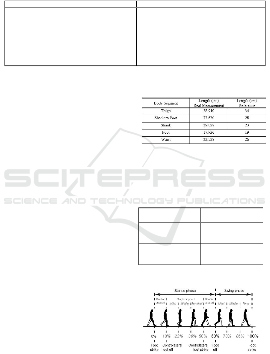
Table 1: Subject’s Inclusion and Exclusion Criteria.
Inclusion
Exclusion
This exoskeleton was aimed towards more flaccid,
hypotonic lower extremity function.
The subject is unable to stand and walk on his own
due to weakness or partial paralysis of leg due to
Spinal Cord Injury, Spinal Muscular Atrophy, Spina
Bifida, or Polio.
Good trunk control.
Preferably, the subject should be able to stand on
their knees and take a couple of steps on their knees.
Pain in ankle and/or knee joint when articulated.
Fragile skin integrity and skin vulnerability.
Poor trunk control.
Moderate to excessive spasticity.
Complete paralysis of lower extremity.
Fragile bone such as in the case of osteogenesis
imperfecta.
2 METHODS
The design overview of the knee and ankle is
composed of a joint that connects thigh and shank
body part. The four-bar linkage mechanism is
applied for the knee joint as it is efficient and
simulates the joint motion and muscle contractions
in the knee (Widjanarko, 2018).
The scope for this project is to implement a
motorized actuator in that case such as a DC Motor
with a rotary to linear output conversion by the
means of lead screw. The chosen actuator is
expected to be able to handle the maximum load
subjected to it through calculation and testing. For
the knee joint specifically, the actuation will be
conducted using four-bar linkage mechanism.
The production process starts with the subject
measurement with provided inclusion and exclusion
criteria. However, the subject measures are only
gathered to specify the user requirement, and is not
intended for direct testing. Followed by gait cycle
analysis to measure the maximum and minimum
angular range of motion on each joint, also to
compute the needed torque and speed respectively.
2.1 Subject Measurement
Before proceeding to the next process, subject
measurement is crucial to determine the limitation
scope that includes load, body segment lengths and
the range of adjustments that the final product must
satisfy. The subject is not limited by a certain range
of age; however, the subject must satisfy the criteria
shown in Table 1. The reason for these exclusions is
to prevent unexpected injuries or complication on
the subject, if the exoskeleton would be tested on a
real subject.
The data will be compared between real life
measurement and the calculation using the
referenced body segment ratio (Winter, 2009). The
reference will be useful to estimate the segment
center of mass, weight ratio and to compare the
length differences of each segment.
Table 2: Body Segment Length.
Referring to Table 2, the subject was measured on
April 8, 2019, with the height of 118 cm and
weighing 27 kg. The ailment should also be noted,
which is Spinal Muscular Atrophy, affecting the
lower limbs. The body segment weights are shown
in Table 3.
Table 3: Body Segment Weight.
Body Segment
Weight (N)
Thigh
26.487
Shank
12.316
Foot
3.841
Upper Body (HAT)
179.582
2.2 Gait Cycle
Figure 1: Human Walking Gait (Bonnefoy-Mazure, 2015).
Mechanical Design of Knee and Ankle Exoskeleton to Help Patients with Lower Limb Disabilities
17
In general, humans walk and run in a common
pattern. A single movement sequence as seen in
Figure 1 above is called as the human gait cycle
which is divided into two phases; the swing phase
and the stance phase. These phases are indicated
when both feet are on the ground (stance phase) and
when one foot is lifted from the ground (swing
phase). Considering the swing phase, in which one
foot is floating, means that the other limb will act as
a support before the person reach their next footing
during the swing phase. The cycle continues by the
switching between the left and right limb
alternatively, performing the walking or running
pattern (Kharb et al, 2011).
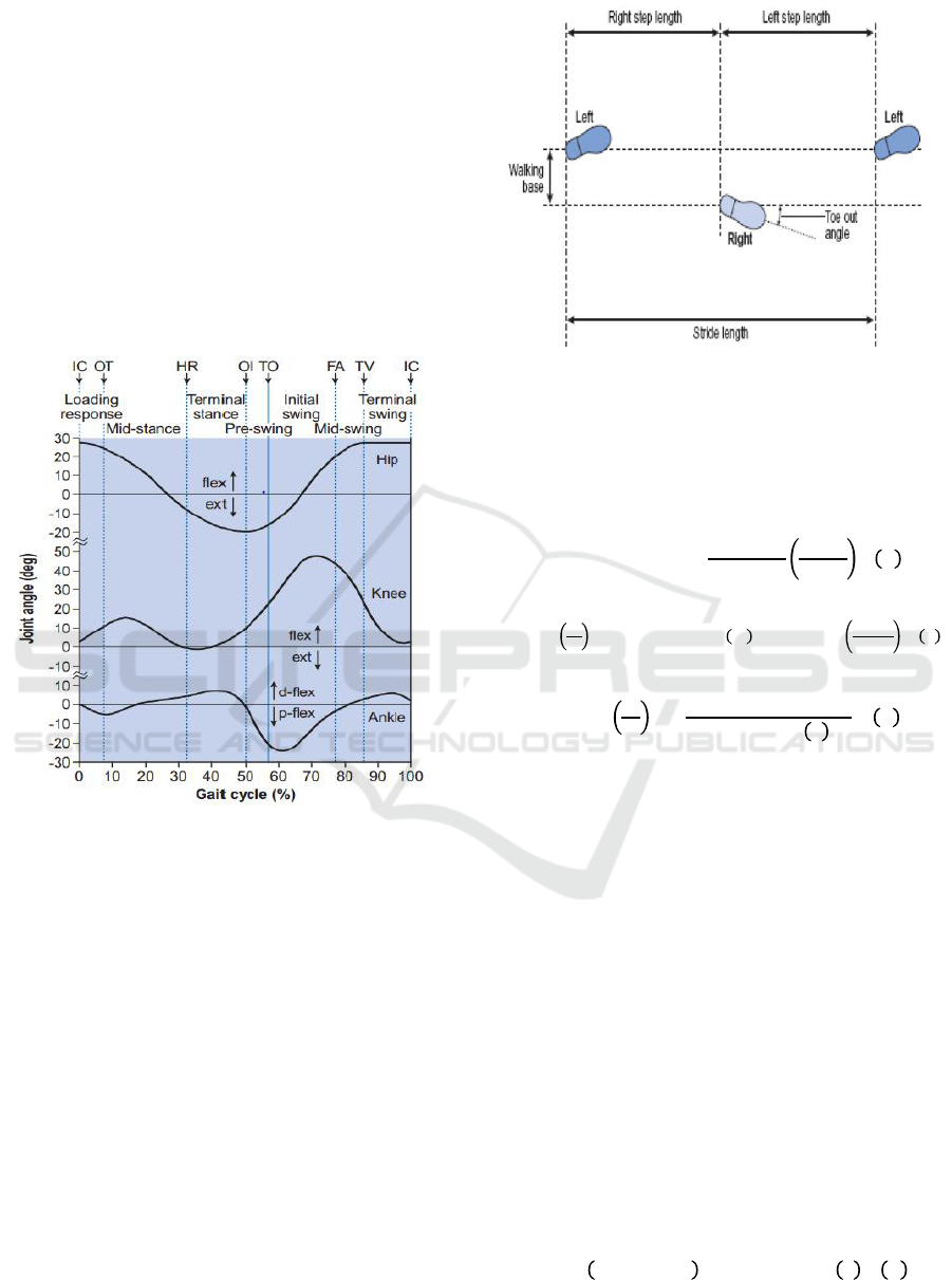
Figure 2: Joint Angle Progression Graph (Whittle, 2007).
The joint angle progression will refer to Figure 2.
The graph will be reverse engineered and estimated
with 0.5º tolerance. According to this data, the
minimal and maximum angle for each knee and
ankle joint respectively are 0º until 47.5º and -22º
until 8º. The polarity of the ankle angle refers to the
dorsiflex (+) and plantar flexion (-).
2.3 Actuation Speed Calculation
The actuation speed also plays a role on the overall
machine performance. Each joint speed could be
estimated using the data from Figure 2 in a single
gait cycle.
Figure 3: Walking Steps Parameter (Kharb et al, 2011)
The parameter as shown in Figure 3 such as the
stride length will be used to calculate the cycle time
(s) and walking speed (m/s) of a person. And the
calculation for these two variables are as follows:
Each person has a distinct stride length on each
gait cycle, even with the same walking speed.
Therefore, the controlled variable in this calculation
are the walking speed = 1.4 m/s (AVG human
walking speed) and stride length = 0.8 m. From
these values, we could acquire the cycle time from
the equation (3), cycle time = 0.571.
Regarding the chosen subject is a child,
approximately nine years old, the controlled
parameters will be halved, however according to
equation (1), the cycle time remains the same. The
angular speed parameters are determined from the
graph in Figure 2, which states the gait cycle
progression (%) and joint angle (º). The range is
determined from the steepest slope, which means the
fastest speed possible.
2.3.1 Required Time and Angular Speed
Equation
KONAS XI and PIT XVIII PERDOSRI 2019 - The 11th National Congress and The 18th Annual Scientific Meeting of Indonesian Physical
Medicine and Rehabilitation Association
18
From equation (4) and (5), the minimum required
velocity of each joint is provided in the Table 4.
Table 4: Joint Velocity.
2.4 Material Selection
Stainless steel pipes will be the primary material
used for the frame, and PETG for motor mountings.
Stainless steel was chosen due to its corrosion
resistance and high tensile strength. While the
remaining concern is the weight, the material will
take form of a pipe to reduce volume. As for the
motor mountings, PETG was chosen due to its
manufacturing capability through 3D printing that
could produce a more complex and flexible design.
The stainless-steel type that will be used as the
exoskeleton frame is 304, as it is one of the most
common types available in general stores. Even
though stainless steel is widely known for its high
corrosion resistance, the design and manufacturing
process should always be monitored (Vaghani,
2014).
For 3D printed material, the PETG was chosen
as it has high ultraviolet resistance in comparison to
ABS and PLA. This property would allow the
exoskeleton for outdoor use, with minimum
probability of deformation.
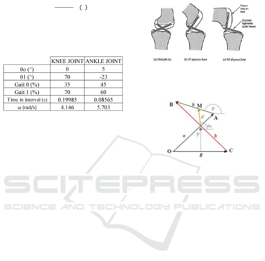
2.5 Four-Bar Linkage
Four-bar linkage mechanism is efficient, provides a
smooth motion and is known to be similar with the
actual knee muscle mechanism (Figure 4).
Figure 4: Human Knee Joint.
Figure 5: Four-Bar Linkage Properties 1 (Widjanarko,
2018).
Represented as a model in Figure 5, the knee
muscles that crosses together are link a and b. In the
actual contraction, however, link a and b changes
length because of the flexing. By implementing this
mechanism, linear displacement and angular
displacement does occur during the locomotion.
Such that it simulates the muscle contraction of the
knee muscles, these displacements can be estimated
and minimalized to obtain an accurate gait
performance and ultimately bestows comfort and
safety for the user, by adjusting the lengths of link a,
b, g and h. These links remain a constant. The link g
will be used as a reference point of the system,
representing the thigh distal end. As well as link h,
representing the shank proximal end.
Mechanical Design of Knee and Ankle Exoskeleton to Help Patients with Lower Limb Disabilities
19
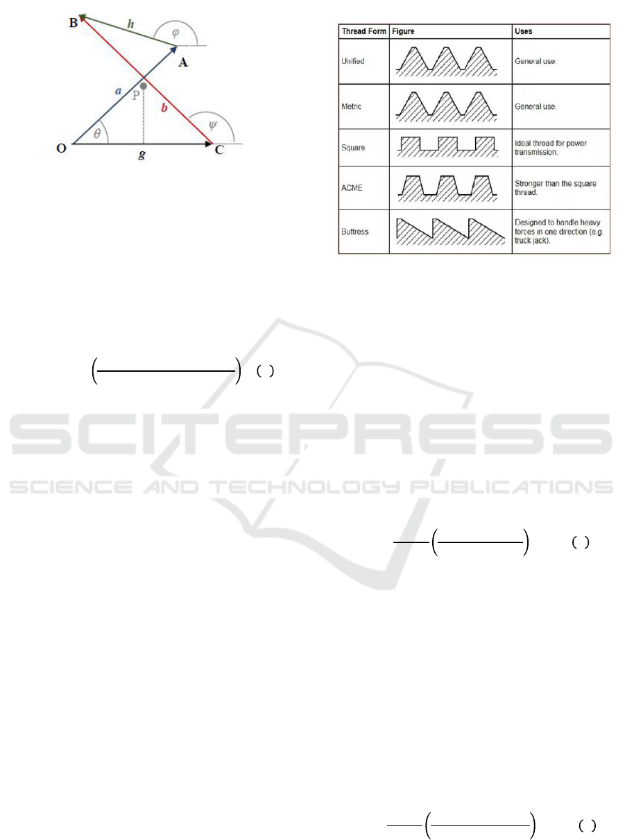
Figure 6: Four-Bar Linkage Properties 2 (Widjanarko,
2018).
The mechanical advantage delivered by this
mechanism may also be noted to produce the highest
efficiency, which primarily relates to the system
angular acceleration. As can be seen in Figure 6, the
output angle (φ) can be determined by two other
variables which are the input (θ) and follower (ψ)
angle using equation (1).
The shank angle with respect to the thigh will refer
to the output angle produced by this mechanism.
2.6 Mechanism Evaluation
A linear actuator is a term in which the output of a
motor is designed such that it is converted into linear
motion. Instead of producing a torque, a linear
actuator produces force to directly push an object. A
linear actuator working principle simply lies to
which type of mechanism it is applied (Budynas,
2008), the more common and less complex
mechanism is by using a leadscrew. The type of
motor used for a linear actuator is not critical as it is
only an output converting mechanism. The draw
back of a linear actuator would be the material used.
Table 5: Leadscrew Types.
There are four types of leadscrew as shown in Table
5. The most common lead screw type available in
the market is ACME thread, which has a distinct
trapezoid thread. The torque calculation needed to
rotate a lead screw mainly refers to these types. For
an ACME thread, the torque required to rotate this
lead screw is slightly larger than the other
counterparts, hence the larger contact area of an
ACME thread. The required torque is also based on
the orientation of the linear actuator.
2.6.1 Linear Actuator Torque
The amount of torque required to drive a leadscrew
to push a certain force is shown in equation (7).
F = Amount of force to be actuated
= The outer diameter of a leadscrew
= lead, equals to the number of start times pitch
length
= friction coefficient between leadscrew and
material
= ACME thread trapezoid angle
Equation (7) computes the amount of torque with a
direction of force against gravity, in other words the
required torque to raise the load. In the other hand,
the torque to lower the load is shown in equation (8).
A self-locking term could also occur when the
required torque is minus.
KONAS XI and PIT XVIII PERDOSRI 2019 - The 11th National Congress and The 18th Annual Scientific Meeting of Indonesian Physical
Medicine and Rehabilitation Association
20
Commonly, an extra component called as thrust
collars are used in a leadscrew mechanism which are
attach to the load end of the leadscrew to lift it.
Since this exoskeleton’s linear actuator design does
not apply this function,
is zero. The constant
values are listed below,
= 8 mm
= 0.25
= 8 mm
= 29º
These constants are related to the dimension, type
and material of the leadscrew.
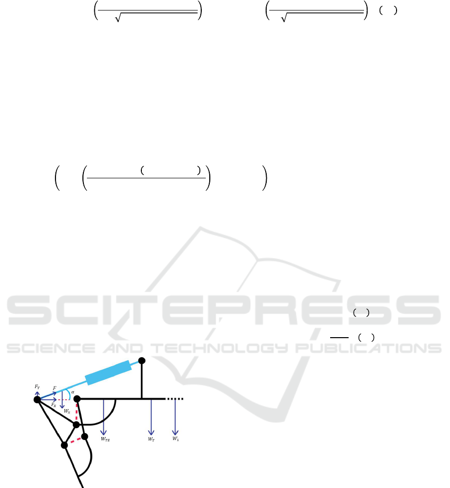
2.7 Frame Model
Figure 7: Exoskeleton Solidworks Model.
The frame model is shown in Figure 7. As
mentioned before, this exoskeleton is classified as an
orthosis which is externally equipped to the subject.
The frame would take an approximately 10 cm space
of the outer sides of the subject’s leg. To attach the
exoskeleton, the frame is equipped with a harness
fabricated through 3D Printing. For the foot model,
the frame was designed suitably for the subject
wearing a shoe. The four-bar linkage links was
designed to be assembled in two different planes to
avoid collision between the parts.
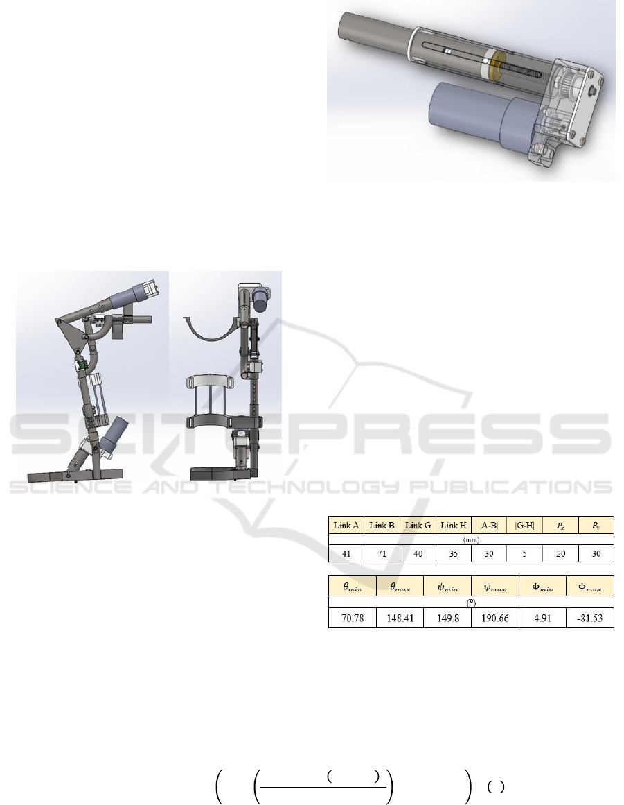
Figure 8: Linear Actuator Model.
The linear actuator design is shown in Figure 8,
equipped with a belt and pulley mechanism to
increase the output torque ratio. The rotary motion is
converted to linear due to the leadscrew rotation
causing the nut to drive back and forth. Both linear
actuator for knee and ankle joint are positioned for
each knee and ankle joint with a pivoting point and
custom displacement range. The pivoting point
allows an angular motion of the actuator during
extension and retraction. The displacement range for
each knee and ankle joint respectively are 8.9 cm
and 0.75 cm. The four-bar linkage mechanism is
only applied for the knee joint instead of both, the
reason being that the knee joint requires a wider
range of angular displacement whilst considering the
required angular velocity shown in Table 4.
Table 6. Four-Bar Linkage Properties.
The link sizes of the four-bar linkage are shown in
Table 6. The minimum angle for both input and
follower angle can be obtained from Solidworks. To
compute both angles with respect to the actuator
displacement is shown in equation (9) and (10).
Mechanical Design of Knee and Ankle Exoskeleton to Help Patients with Lower Limb Disabilities
21
The numbers are in accordance to the segment
sizes of the frame and solved using trigonometry. As
can be seen in equation (9). the follower link is
dependent to the input link. Using the equation of
output angle (10)., the output angle can be computed
using the variables in Table 6.
Represented as Φ, the output angle at maximum
is -81.53º deducted from the calculation as it
changes into a different quadrant, while the real
maximum value of the output angle is to be added
by 180º. Therefore, the angular movement range of
the knee joint is 93.56º by design.
As for the ankle joint, by using the same
trigonometry method, the relation between the ankle
angle and the ankle linear actuator displacement is
shown in equation (11).
The maximum dorsiflex angle is 8.18º and for the
plantar flexion is 21.71º (-).
2.8 Torque Calculation
Linear actuator converts rotary motion to linear
motion; therefore, the required torque of the motor is
based on the amount of force subjected to each
linear actuator.
2.8.1 Knee Joint
Figure 9: Knee Joint Frame Free Body Diagram.
The knee joint free body diagram is shown in Figure
9. The force that is going to be calculated is the
static force during a sitting position which is
presumed to have the highest amount of force. The
variables required to find F are listed below,
= Weight of LM inner shell
= Weight of Thigh Exoskeleton (Includes one
harness, MPU mount)
= Weight of Upper Body
= Weight of Thigh
The weight of the exoskeleton was estimated using
Solidworks, while the weight of body segments
refers to Table 3.
;
Through static force equilibrium (12) and
equation (13) the maximum amount of force acting
on the knee linear actuator is 351.454 N. The angle
is 19.95º obtained from Solidworks.
As the acting force has been computed, the
torque to raise and lower the load respectively are,
0.934 Nm and -0.042 Nm.
KONAS XI and PIT XVIII PERDOSRI 2019 - The 11th National Congress and The 18th Annual Scientific Meeting of Indonesian Physical
Medicine and Rehabilitation Association
22
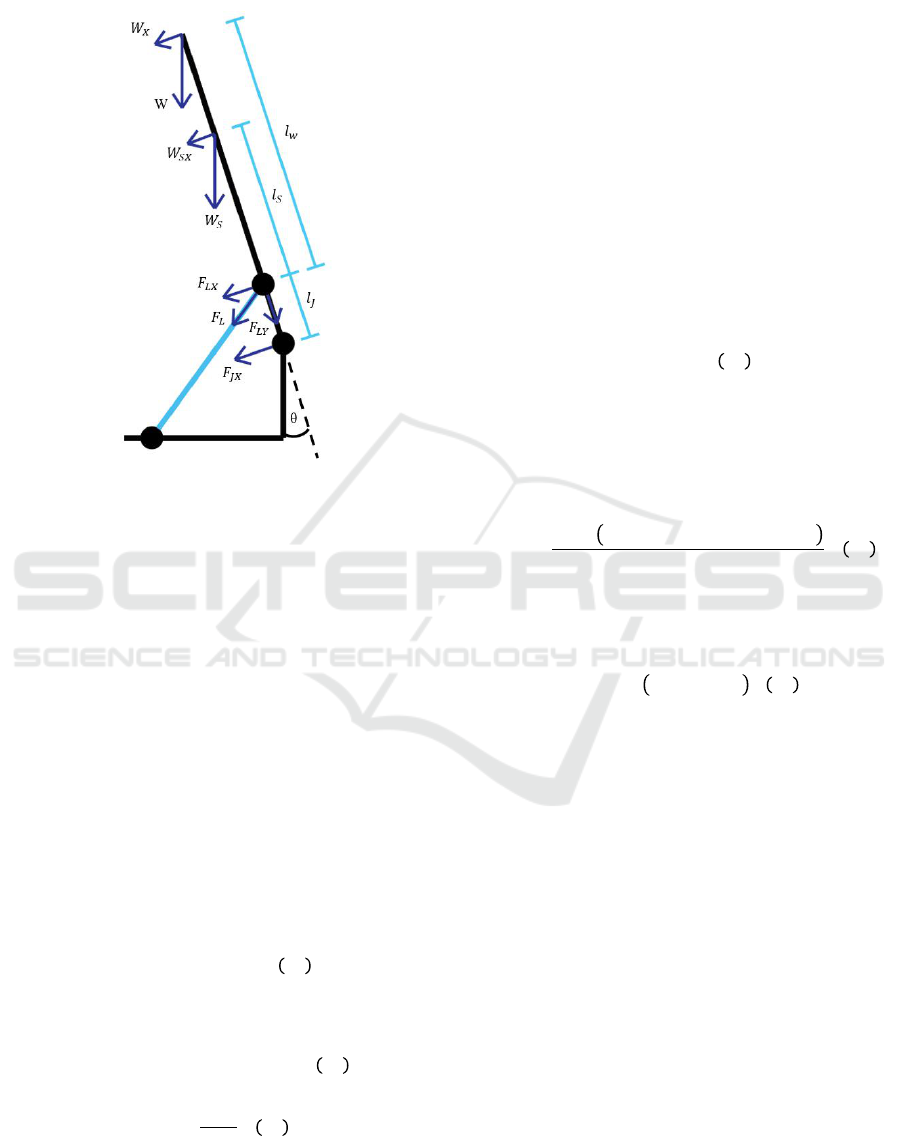
2.8.2 Ankle Joint
Figure 10: Ankle Joint Frame Free Body Diagram.
The ankle joint free body diagram is shown in
Figure 10. The force is calculated during terminal
stance when the angle θ is at 8.18º. The variables
required to find F are listed below,
W = Weight of the upper body, one thigh, and one leg
in addition to the weight of the Knee LA, Thigh
Exoskeleton
= Weight of Shank in addition to shank
exoskeleton frame
= Amount of force the Ankle LM must endure
= Amount of force affecting the ankle joint
= W arm length
=
arm length
=
arm length
= 0;
Using the moment and force equilibrium method
(14) and (15), the force subjected to the ankle linear
actuator can be calculated with equation (16) that is
358.505 N with α (the angle between linear actuator
and shank) at 55.86º.
Therefore, the required torque to raise and lower
the load for ankle linear actuator respectively are
0.953 Nm and -0.043 Nm.
2.9 Inertia Calculation
During swing phase the actuators needs to withstand
the inertia of the bottom half of the leg, which is
mostly subjected to the knee joint actuator. To
calculate the inertia, the equation is based on a
simple pendulum inertia,
The
refers to the mass of the both shank and foot
, and
is the centre of gravity of the shank
and foot (
). The center of gravity can be
calculated using equation (18).
Substitute equation (17) in terms of total body mass
and height, the inertia equation (19) can be obtained.
2.10 Motor Type Selection
The type of motor chosen for the linear actuator is a
DC Motor. According to torque calculation in
subchapter 2.8, the torque required is not as
demanding as opposed to the speed requirement.
Considering the weight of the motor would affect
significantly to the exoskeleton load, a compact and
lightweight motor is preferable and should be taken
into account.
However, a motor with these specification,
especially with a compact size, is difficult to find in
the market and mostly come with a large dimension.
Therefore, one aspect should be sacrificed between
speed and torque and for this project, the torque is to
be prioritized.
Mechanical Design of Knee and Ankle Exoskeleton to Help Patients with Lower Limb Disabilities
23
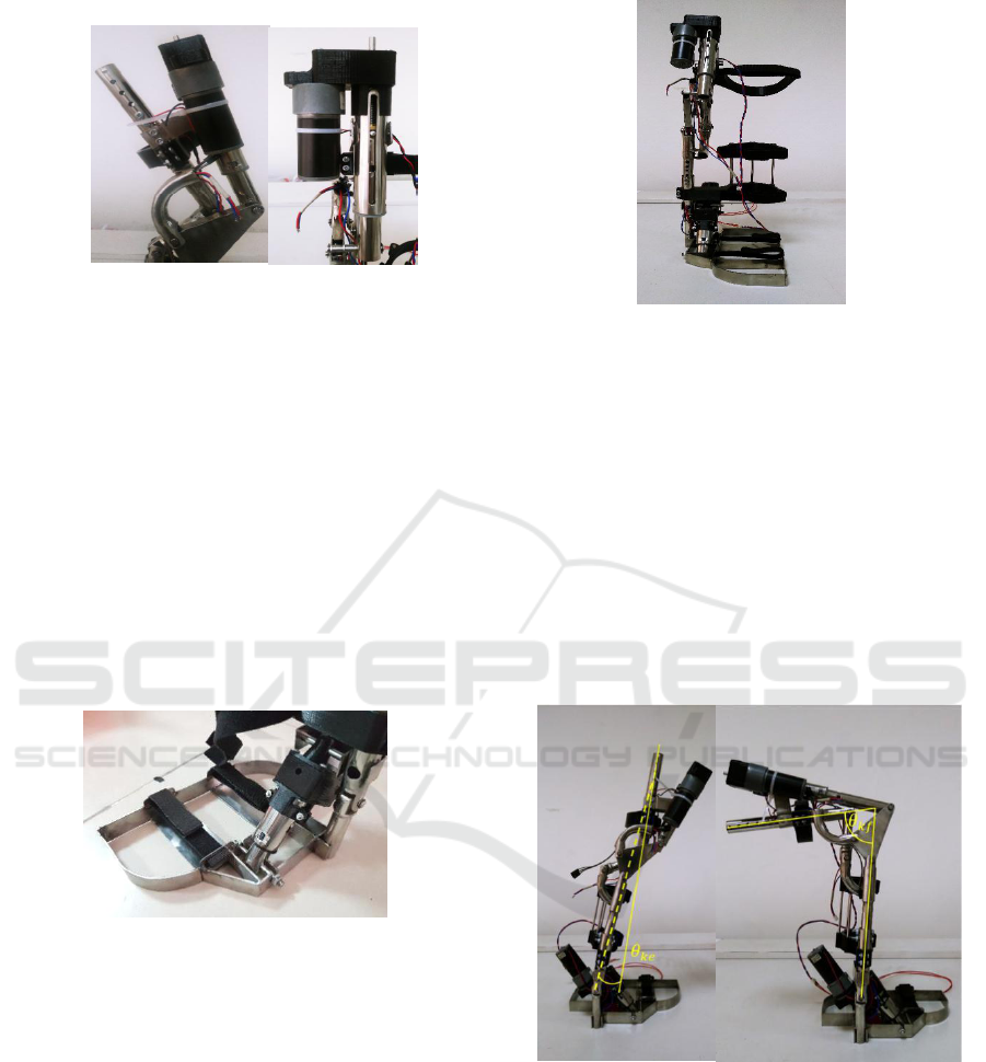
Figure 11: Exoskeleton Final Product.
3 RESULT & DISCUSSION
The final product of the exoskeleton is shown in
Figure 11. It weighs 2.055 kg for each leg. The
material used for the frame is made of stainless steel.
However, the type may vary between 304 and 201
because of manufacturing miscommunication. The
pipe shaped stainless steel is also useful for cable
management. The foot harness is made from PETG
through 3D Printing, the same as the motor
mounting. The harnesses are equipped with Velcro
to fasten. The shank segment was made to be
adjustable, in the range of 5 cm.
Figure 12: Foot Frame.
As seen in Figure 12, the footing is also equipped
with Velcro fastener. To the right, the linear actuator
of the ankle joint was manufactured as it was
designed, connecting the foot segment to the shank
segment.
Figure 13: Knee Joint Actuator.
The knee linear actuator connects the thigh
segment with the triangle part which drives the four-
bar linkage mechanism to rotate the knee joint.
Apart from the whole exoskeleton, the knee linear
actuator weighs 0.520 kg each, while the ankle
linear actuator weighs 0.395 kg each.
3.1 Range of Motion
The range of motion was tested by powering each
linear actuator to reach the minimum and maximum
linear actuator displacement after product assembly.
The angle is the measured using a protractor.
Figure 14: Knee Actuator Movement Range.
Figure 14 shows the maximum extension and
flexion angle denoted as
and
. Respectively
and
are 98.5º and 5º, therefore the range of
angular motion of the knee joint is 94.5º.
KONAS XI and PIT XVIII PERDOSRI 2019 - The 11th National Congress and The 18th Annual Scientific Meeting of Indonesian Physical
Medicine and Rehabilitation Association
24
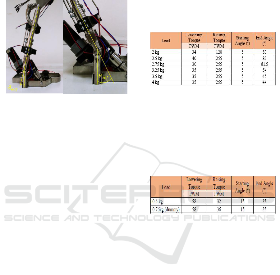
Figure 15: Ankle Actuator Movement Range.
Figure 15 shows the maximum dorsiflexion and
plantar flexion angle of the ankle joint, denoted as
and
. Respectively
and
are 15º
and 22º, therefore the range of angular motion of the
knee joint is 37.
The test result shows an accurate result in
comparison to the calculation, especially for knee
extension, flexion and plantar flexion of the ankle
with a slight error. However, the dorsiflexion angle
shows a larger value than expected.
It has been concluded that these errors were the
result of manufacturing imperfections in addition to
the linear actuator mountings which is made from
PETG that could deform far easily. Not to mention
that the range of motion was tested without any
additional load added to the exoskeleton which may
result in a larger error and even reach a breaking
point. The adjustment part of the shank segment
could also affect the test result due to the pipes
having different dimension that creates a gap that
causes the frame to tilt approximately up to 3º.
3.2 Load Test
Load testing was conducted to obtain the PWM
value when the linear actuator is subjected to a
certain load. The PWM value will then be
conditioned to the amount of load is being used
when conducting the gait analysis. The test resulting
the values below is obtained when the leg is in Mid-
swing stance. The tests are done using a 24V battery
cell.
Table 7: Knee Joint Load Test.
The PWM value reached its maximum value when
2.5 kg load is subjected to the linear actuator. This is
the point in which the end angle is starting to shorten,
as more load applied to the device. This value might
be affected by the slipping of the timing pulley and
the thrusting point shaft not being concentric with
the triangle. After certain cycles. The PETG
mounting shows a slight deformation, making the
inner shell and outer shell tilting.
Table 8: Ankle Joint Load Test.
The data collected when testing the ankle linear
actuator is not as complete as the knee linear
actuator. This is due to the slipping of the timing
pulley when higher load is added. The 0.6 kg is the
weight of the foot frame.
3.3 Actuation Speed Test
The linear actuator speed test was done by
incrementing PWM gradually and measure the speed
in which the linear actuator reach maximum its
maximum range. No additional load was added to
the system to confirm the calculation as well. The
test was done using a 24V power supply and a motor
driver to control the PWM.
Mechanical Design of Knee and Ankle Exoskeleton to Help Patients with Lower Limb Disabilities
25
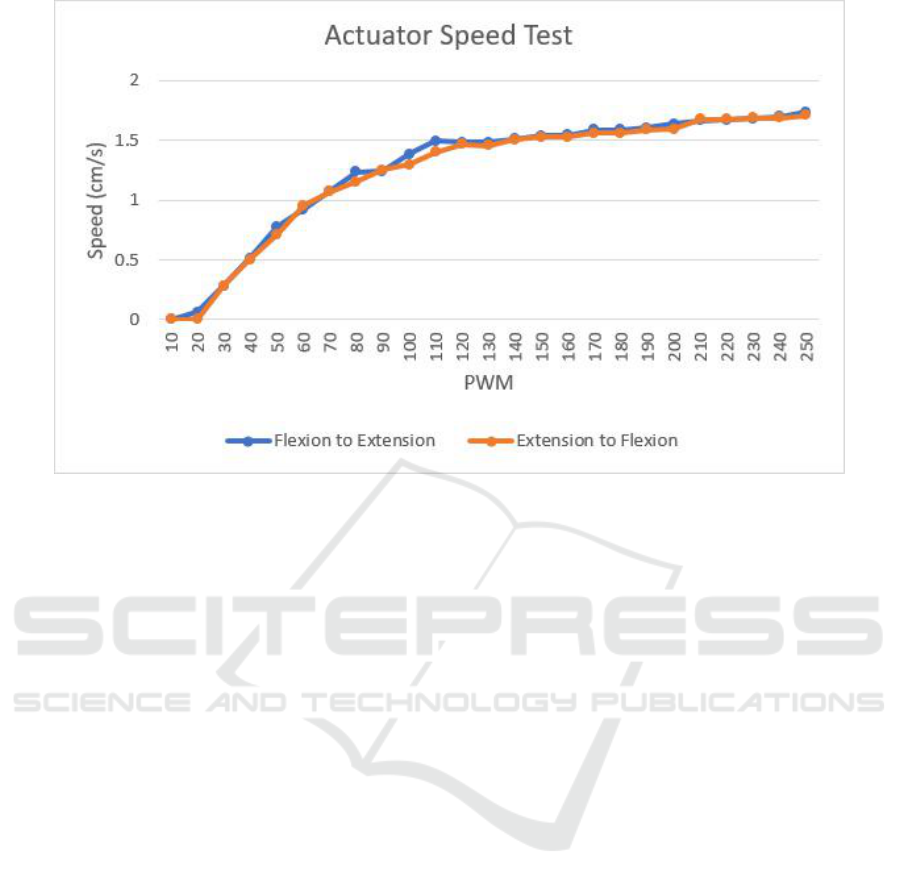
Figure 12: Actuator Speed Progression
Figure 12 shows the progression of actuation
speed when given a certain amount of PWM.
According to the graph, the speed starts to slowly
increase after reaching 140 PWM, meaning the
motor is in the range of its rated output power.
Notice that there are two curves, this is to show the
difference when the linear actuator undergoes a
raising torque and lowering torque. The maximum
speed that the motor could produce is 1.738 cm/s.
Comparing to the required angular speed of each
joint in Table 4, the angular speed produced by the
linear actuator can be computed by inverting
equation (11). The ankle equation was chosen since
the required speed of the ankle joint is bigger than
the knee, in addition to the same motor used for all
linear actuators. The angular speed produced by the
linear actuator is 6.51 times slower than the
requirement.
4 CONCLUSIONS
Since the linear actuators are subjected to a large
amount of force, different material such as
aluminium is recommended to replace the motor
mountings. A tensioner would also be recommended
if the motor driving has fewer torque than needed
running in a belt mechanism.
The data shown in Table 6 nonetheless shows a
promising power produced by the linear actuator.
However, the speed is much less than the required
amount, meaning that the subject could not walk as
fast as the human average walking speed. Therefore,
this product is more recommended to be used as a
rehabilitation or slower activities.
REFERENCES
Bonnefoy-Mazure, A., Armand, S., 2015. Normal Gait,
Nova Science Publishers, Geneva, Switzerland. pp.
200-211.
Budynas, R.G., Nisbett, J.K., 2008. Shigley’s Mechanical
Engineering Design, The McGraw-Hill Companies, 8
th
ed., pp. 400-408.
Chen, B., Ma, H., Qin, L., Gao, F., Chan, K., Law, S., Qin,
Ling., Liao, W., 2015. Recent Developments and
Challenges of Lower Extremity Exoskeletons, Elsevier
Pte Ltd. Singapore.
Kharb, A., Saini, V., Jain, Y.K., Dhiman S., 2011. A
Review of Gait Cycle and Its Parameters, International
Journal of Computational Engineering & Management.
Vol. 13.
Vaghani, M., Vasanwala, S.A., Desai, A.K., 2014.
Stainless Steel as A Structural Material: State of
Review. International Journal of Engineering Research
and Applications. Vol. 4. Pp. 657-662.
Wang, D., Guo, J., Lee, K., Yang, C., Yu, H., 2011. An
Adaptive Knee Joint Exoskeleton Based on Biological
Geometries. IEEE International Conference on
Robotics and Automation. Shanghai.
KONAS XI and PIT XVIII PERDOSRI 2019 - The 11th National Congress and The 18th Annual Scientific Meeting of Indonesian Physical
Medicine and Rehabilitation Association
26

Whittle, M., 2007. Gait Analysis: An Introduction.
Elsevier, 4
th
ed.
Widjanarko, D. A., 2018. Knee Exoskeleton with Control
System and Pneumatic Air Muscle Actuation, B.Eng.
thesis.
Winter, D. A., 2009. Biomechanics and Motor Control of
Human Movement, Wiley, Hoboken N.J. 4
th
end, pp.
82-106.
Mechanical Design of Knee and Ankle Exoskeleton to Help Patients with Lower Limb Disabilities
27
