
Scalable Resilient Internal BGP: Fast Recovery Mechanism Provide
Multi-link Environment Carrier Ethernet Backhaul
Hillman Akhyar Damanik
Universitas Budi Luhur
Keywords: i-BGP, Failover, 802.1Q, Routing Policy, Match Prefix (Route Filters) IP Addresses (Routes), Policy Match
Conditions, Carrier Ethernet, Policy Chains, and Routing Decisions.
Abstract: Implementing and modeling technology in the Datacom environment, for the Multipath method with
autonomous routing is one of the most useful and promising developments and trends in building a packet
routing policy system for the next generation. Offering lower bandwidth scalability, popularity is also
driven by unprecedented growth in network traffic. The use of video, mobility, the shift from TDM
networks to IP, cloud services, smart cities, and the Internet of Things (IoT) are the main generators of that
growth. However, gradually changing the routing between the current domain from one path to the
multipath link for the failure process and link recovery is a problem. Several studies carried out in previous
studies on the Border Gateway Protocol (BGP) routing protocol method, were implemented with connection
status, with an external method called the External Border Gateway Protocol (e-BGP). Between the
Autonomous System Number (ASN) on the internet peering session. The method and scheme in the paper,
we study and present the impact of implementing policies and rules, routing traffic in the Datacom Ethernet
environment, by implementing internal BGP and integrating with method 802.1Q (dot1Q), for failure and
recovery of links and nodes in multipath links. Use routing policy features and models is expression policy
route, firewall filters route, route term preferences, chain policies, and policy statements. The results
obtained from the two methods that will be carried out in the multipath link environment, show and produce
that periodic the intervals obtained in the graph and testing with ICMP and traceroute packet, have a direct
average correlation with a link failure. Failure of a node in the main or primary link fails, secondary or
backup links are inactive status and are ready to make a recovery and then on tertiary links by selecting the
round-robin method in performing recovery. The recovery link transfer process from the results obtained is
0-2 and 0-5 m/s.
1. INTRODUCTION AND
RESEARCH OBJECTIVES
Ethernet Datacom business services, at layer two
and layer 3, are attractive solutions in a vast area
network of both the internet and metropolitan,
especially in dot1q tunneling and BGP technologies
because they offer a cost-effective way to provide
high-speed data services. These services offer lower
costs per bit and bandwidth scalability; the
popularity of Ethernet is also driven by
unprecedented growth in network traffic. The use of
video, mobility, the shift from TDM networks to IP,
cloud services, smart cities, and the Internet of
Things (IoT) are the main generators of all
technological growth [2] [3] [4]. Be advised that
papers in a technically unsuitable form will be
returned for retyping. After returned, the manuscript
must be appropriately modified. However, simplicity
and cost-effectiveness come with two main
disadvantages: poor support for traffic engineering,
and slow failure recovery times [5] [6]. The
incorporation of dot1q tunneling technology and
internal BGP on the paper is to minimize and
develop accelerated shipments, fast recovery,
converge on the network, and anticipate network
failures. Using Q-in-Q tunneling, providers can
separate or group customer traffic into fewer
different VLANs or VLANs by adding another layer
of 802.1Q tag. Q-in-Q tunneling is useful when
customers have overlapping VLAN ID because the
customer's VLAN 802.1Q (dot1Q) tag is preceded
by an S-VLAN (VLAN) service tag. Tunnel
translations are Q-in-Q and VLANs to isolate
Damanik, H.
Scalable Resilient Internal BGP: Fast Recovery Mechanism Provide Multi-link Environment Carrier Ethernet Backhaul.
DOI: 10.5220/0008931701970208
In Proceedings of the 1st International Conference on IT, Communication and Technology for Better Life (ICT4BL 2019), pages 197-208
ISBN: 978-989-758-429-9
Copyright
c
2020 by SCITEPRESS – Science and Technology Publications, Lda. All rights reserved
197
customer traffic on one side or to allow customer
traffic flow between cloud data centers in various
geographical locations or metropolitan areas [7]. In
Internal Policy BGP has provided a set of rules or
policies, how to determine how AS Numbers can
direct the traffic process both when traffic comes in
and out of and to the internet or between AS
numbers. The concept is carried out in the BGP
protocol; there will be routing chosen and advertised
based on the process to and from the destination
network scale to be determined [8]. The concepts
and methods carried out in the internal BGP session
will be interconnected between two BGP peering,
which has the same AS Number [9]. The method of
applying BGP is used for two or more gateways
when packets from the source address, or to deliver
packets to destinations in terms of exchanging
information. The ISP and NAP Providers in using
and utilizing the BGP protocol method are for the
distribution of information, inter-domain routes to
the internet [10] [11] [12]. In this paper, we present
the IBGP application to the Datacom Metro-E
(802.1Q) environment in backhaul transmission.
Writing this research paper presents a transmission
scheme in the tunneling Datacom Metro-E dot1q
(802.1Q) layer 2, with the Layer 3 (i-BGP) routing
protocol. The sending process that continues the
communication of data traffic from the remote site
to the backhaul provider router to be able to carry
the transmission backhaul communication
connection to the destination. The method and
scheme of incorporation applied to the Metro-E
dot1q and i-BGP lines are used because of its ability
to choose the best route to the destination, especially
in multipath environments. Tolerance to connection
errors is highlighted in the challenge to the
Multipath network. Internal BGP methods and
concepts will be used in the Metro environment, and
the results will provide reliability in ensuring the
delivery of user traffic. This internal BGP
implementation will describe a failure technique and
the length of the recovery process and aims to
provide reliability realization to multipath networks
and also to generate scalability and network
performance. Multipath link environment in
backhaul will be used two methods, namely Dot1q
Tunneling at Layer 2 and Internal BGP to classify
and route each source address to a destination
(peering session). The AS values used are ASN:
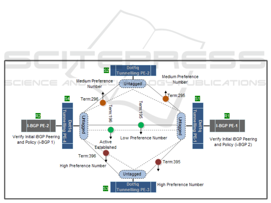
45679-45689, and 45699. The concept and method
of Dot1q Tunneling at Layer 2 and Internal BGP in
the multipath environment for the backhaul link will
be described and explained, as shown in figure.1.
Figure 1: Dot1q Tunnelling and internal-BGP Architectural Multipath Link Layers End-to-End Scheme
ICT4BL 2019 - International Conference on IT, Communication and Technology for Better Life
198

2. BENEFITS OF INTEGRATING
MULTI-LINK METRO DOT1Q
TUNNELLING METRO-E AND
I-BGP BACKHAUL
Datacom's network and transportation consist of
multi-layered networks, technology, and distribution
areas [14]. Integrate, and combination of layer two
and layer 3 for error link implementation is very
suitable to be applied to the Metro-E environment.
Layer 3 Technology consists of, one of which is IP
networks, namely Internet Address Protocol (IP).
Today's IP Address has become a global standard for
networks. At IP Networks carry data traffic from
applications that are time-sensitive [13]. Routing
methods are processes that determine the path that
data or packets followed and to travel across
multiple networks from the source node to the
destination node. When traveling in data networks
are routed through a series of routers and multiple
networks, in the medium to large scale. In the
process of this routing term, for example, the link
and router fail the target node will not be reachable
from the source node that causes network fail.
Several possibilities cause network failures, such as
link failures or vertices in the path, administrative
changes, overloaded IGP settings, and path
optimization [15]. Apart from link failure,
bottlenecks in link links are also a challenging
problem for network service providers (Network
Access Providers) [16]. Here are some reasons that
can cause network failure [17] [18].
1. Physical layer (L1) in the Fiber Optic ring
when it breaks
2. Software failures and errors.
3. Hardware failures and errors.
4. There is no planned maintenance or (not
upgraded) hardware failure
5. Process the excess and processor capacity also
causes the router.
The process of implementing failures on
multilink technology links is beneficial for access
provider providers because with the development
and tools available on current technology, losing
link connectivity on the primary device is very
detrimental. The link can be replaced by another link
backup [19].
Process of recovery to link connectivity in this
research will be carried out when this failure occurs;
all network links must be converged before traffic
will be able to pass to and from network segments
that experience link fails [20].
3. RESEARCH METHOD
CONFIGURATION AND
SCHEMA
The methodological scheme of this research paper is
to propose, study, develop and implement routing
policies on the internal Border Gateway Protocol (i-
BGP), integrated on the Dot1q Tunneling Metro line
in routing distribution and carrying backhaul traffic
that stands at Metro Multi-link Dot1q tunneling is
policy expression, firewall filter, route preference,
policy chain, and policy statement in the link
recovery and failover process.
3.1 Evaluating and Configuring Scheme
and Method
3.1.1 Evaluating Match Condition and
Actions (Matching Route) Method
The method of application is to evaluate complex
cases using a chain of policies and subroutines on
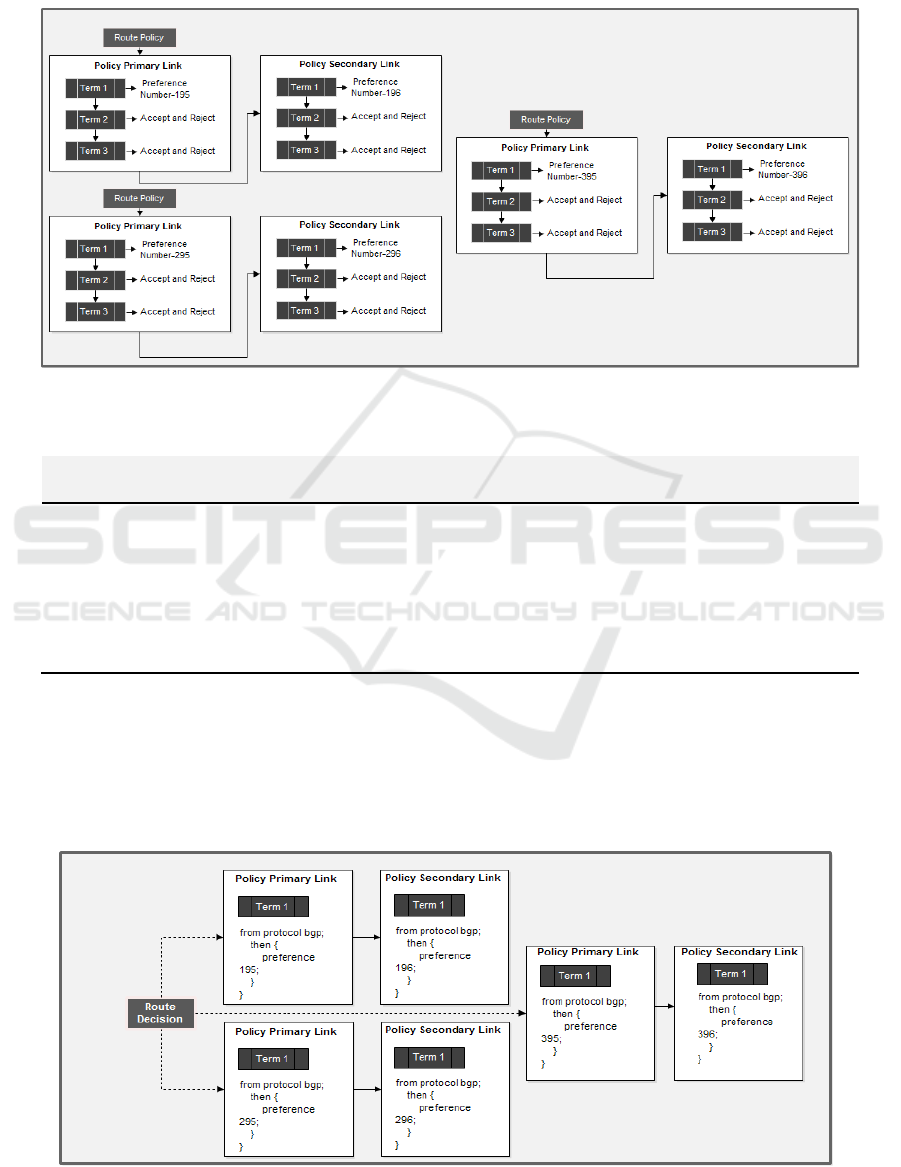
the scheme. In figure 2 shows how the route-policy
will be evaluated. This route process policy consists
of several terms. Then each term consists of
conditions and matches actions to be applied to the
appropriate route [21]. The following policies will
evaluate each subsequent route:
Procedure: match conditions and actions to apply to
match routes:
1. Evaluate Packet Term 1: Route 1 will be
evaluated if the route matches then action will
be taken.
If the next routing policy
is to accept and reject actions will be
determined, and packet routing will be
skipped.
2. Evaluate Packet Term 2: Route 2 will be
evaluated if the route matches then action will
be taken.
If the next packet route action
accepts and rejects, then the action will be
taken, then the action will evaluate the packet,
and then the packet ends.
Term 2: If the next action is not specified,
evaluation of the packet route will proceed in
the same manner as the
route-policy
carried out first. Moreover, the
next action
will be determined: accept and reject the term
will be skipped.
3. Evaluate Packet Term 3: If the packet route
does not match the
next policy route and
also the first route policy, the route will be
Scalable Resilient Internal BGP: Fast Recovery Mechanism Provide Multi-link Environment Carrier Ethernet Backhaul
199
evaluated on the first term carried out on the
second route policy
4. Evaluate Packet Term 4: Route will continue
until the route is appropriate than the act of
accepting and reject the packet when
evaluated
Figure2: Proposed Using Term Policy Chains and Routing Decisions Schema
Table 1: Route preference rules and IP Address P2P IBGP
Source
Address Traffic
Route
Gateway
Preference
Number
Priority Term
10.17.0.0/16 10.10.5.6/30 195 1 Primary
10.17.0.0/16 10.10.5.8/30 196 2 Secondary
10.18.0.0/16 172.30.0.6/30 295 1 Primary
10.18.0.0/16 172.30.0.8/30 296 2 Secondary
10.19.0.0/16 192.168.252.6/30 395 1 Primary
10.19.0.0/16 192.168.252.8/30 396 2 Secondary
Modeling and failover analysis for IP Address
P2P will be used number preference values. The
route term preference of the Administrative Distance
(AD) value is 232 – (1).
Table 1 above it contains several route rules and
priority rules with several i-BGP IP Address P2P.
Values of preferences, priorities, and terms can be
seen in the following table.1 above:
Figure3. Proposed route rules and priority schema
ICT4BL 2019 - International Conference on IT, Communication and Technology for Better Life
200
3.1.2 Match Prefix (Route Filters) IP
Addresses (Routes).
Match Prefix Package (Route Filters) IP Addresses
(Routes) is a collection of prefix addresses in the
form of source addresses. Determining the start of
the route of the match, the configuration process will
be determined by the Match Prefix (Route Filters)
Package IP Addresses (Routes).
The match prefix packet option will be used to
match the route address to which the matching
prefix matches any type except for the unicast
source address. The Match Prefix (Route Filters)
package detailed IP Addresses (Routes) for the
routes that are applied are in the range of subnet IPs
Address 10.17.0.0/16-10.18.0.0/16 and 10.19.0.0/16.
Procedure Match Prefix and IP Address Routes:
1. First Term: the source-address-filter
action option will be taken after a match
occurs, and the statement is then
accepted and rejected
2. Second Term: Action will be taken when
the match value occurs. However, no action
is specified for the choice of route-filter
options or source-address-filters.
3. Third Term: Match prefix and IP address
routes match types prefix-address list is
scheme:
- Route and address as the match prefix
address list (destination-source
prefix).
- Component Tree Radix address of
the match prefix address is equal to the
route prefix length addresses.
- Statement route-filter and src-address:
configure [policy-statement
primary link-outbound traffic {
term 2 {
from {
route-filter prefix-source-
address exact;
then accept {
}
Term 3 {
Then reject; } }
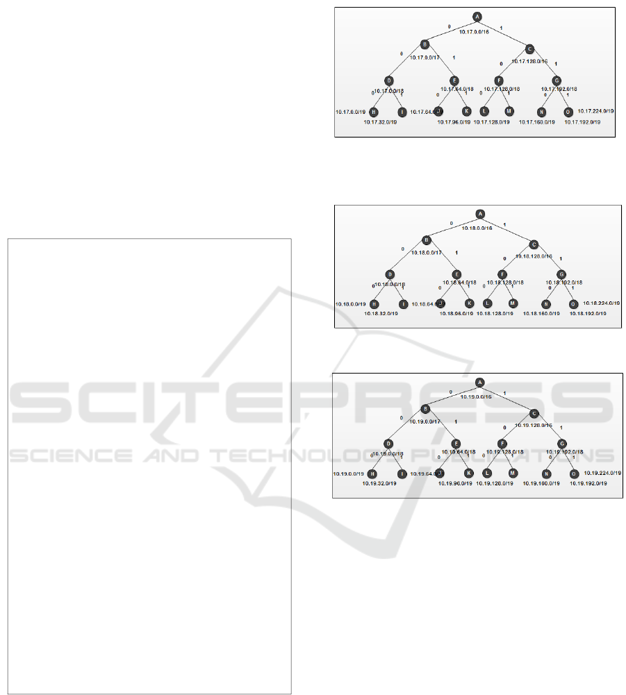
Process classification for match prefix packet
operations to be used, router devices (i-BGP) and
will be configuring by classifying suitable binary
numbers known as radix trees. Figure 4: portion IP
Address the (radix tree) uses binary search to
identify the IP address (route) for route filters. The
proposed portion IP Address can be a graphical
representation of the following numbers.
Figure 4. Match Prefix and IP Addresses (Routes)
(10.17.0.0/16)
Figure5. Match Prefix and IP Addresses (Routes)
(10.18.0.0/16)
Figure6. Match Prefix and IP Addresses (Routes)
10.19.0.0/16)
3.1.3 Configuration Collection of Match
Prefixes (Route Policy Match
Conditions) Scheme
Terms of policy match determine the criteria that
must match the route. Match conditions include
community, prefix-length address, and AS Number
path. AS Path, Regular Expression to be used as a
Routing Policy matching condition, each term can
consist of a statement, from which defines the
matching condition: a from the statement, the
definition of criteria that must match the address of
the private group that entered. The next action is to
determine one or more conditions of the match.
Conditions must match the internal group of the
route so that a match occurs. The Term in the route-
policy will include a statement is from to determine
Scalable Resilient Internal BGP: Fast Recovery Mechanism Provide Multi-link Environment Carrier Ethernet Backhaul
201

the condition that the route must match the
applicable policy:
set: policy-options
action: policy-statement Primary-
Link
action: term 1 {
from protocol ibgp {
Then preference 100;
action: term 2 {
Then accept;
action: term 3 {
Then reject;
set: policy-options
action: policy-statement
Secondary-Link
action: term 1 {
from protocol ibgp {
Then preference 100;
action: term 2 {
Then accept;
action: term 3 {
Then reject;
3.1.4 Concept and Configuration Topology
VLAN Q-in-Q Tunneling Schema
The application and testing value of tunneling dot1q
VLAN Q-in-Q that will be studied and analyzed in
this paper is to combine the internal Dot1q and BGP
methods at layer 3. The Dot1q tunneling process will
transparently pass Metro Ethernet traffic that is
connected directly from the VLAN and will carry a
VLAN from range 1-4094. This method is beneficial
when a customer from a provider (ISP) will pass
traffic from a remote site to its destination; in this
case, communication that is a geographically
different location.
Figure7. Concept and Configuration Topology VLAN Q-
in-Q Tunneling Scheme
In applying the dot1q method to tunneling
VLAN q-in-q in figure.7 above this service provider
network, 1-4094 customer VLANs are mapped to a
VLAN service. Figure.7 configuration facing
interface for topology.
Table 2 Configuration facing interface of topology for
setting up Q-in-Q Tunneling (Dot1q).
Interface Port Status Dot1q
ge-0/0/0.0
Untagged
customer-facing access
C-Vlans 1-
4094
ge-0/0/1.0
Untagged
customer-facing access
C-Vlans 1-
4094
ge-0/0/2.0
Untagged
customer-facing access
C-Vlans 1-
4094
ge-0/0/3.0
Untagged
customer-facing access
C-Vlans 1-
4094
ge-0/0/4.0
Untagged
customer-facing access
C-Vlans 1-
4094
ge-0/0/5.0
Untagged
customer-facing access
C-Vlans 1-
4094
ge-0/0/6.0
Untagged
customer-facing access
C-Vlans 1-
4094
4. DESIGN INTEGRATE I-BGP
PROVIDE FAILOVER IN
MULTI-LINK ENVIRONMENT
BACKHAUL
Internal BGP Enhancement Process for Quick
Recovery Mechanism Provides Multi-Link
Environment Carrier Ethernet Backhaul, and
application specifications and topology
configurations will be modeled as Figure 8.
Topology scheme design and configuration will be
modeled are from the customer's remote site to the
backhaul router provider (ISP). The allocation of
bandwidth width at the transport link is 60 Mbps;
this bandwidth pipe width will bring traffic to all
customers. The Layer 2 application, Dot1q, is used
to process running traffic to determine route on the
transmission line. Layer 3 services will bring all
remote site traffic. The detailed process can be seen
and illustrated in Figure 8 below The standard
configuration of interface ports for each port will be
marked to bring traffic to communications that will
be integrated with BGP internals. On the router side,
the AS Number will be allocated to each primary
and secondary link group, 45679-45689 and 45699.
The internal BGP work process will function as a
failover link and will be managed by an internal
BGP peering session
ICT4BL 2019 - International Conference on IT, Communication and Technology for Better Life
202
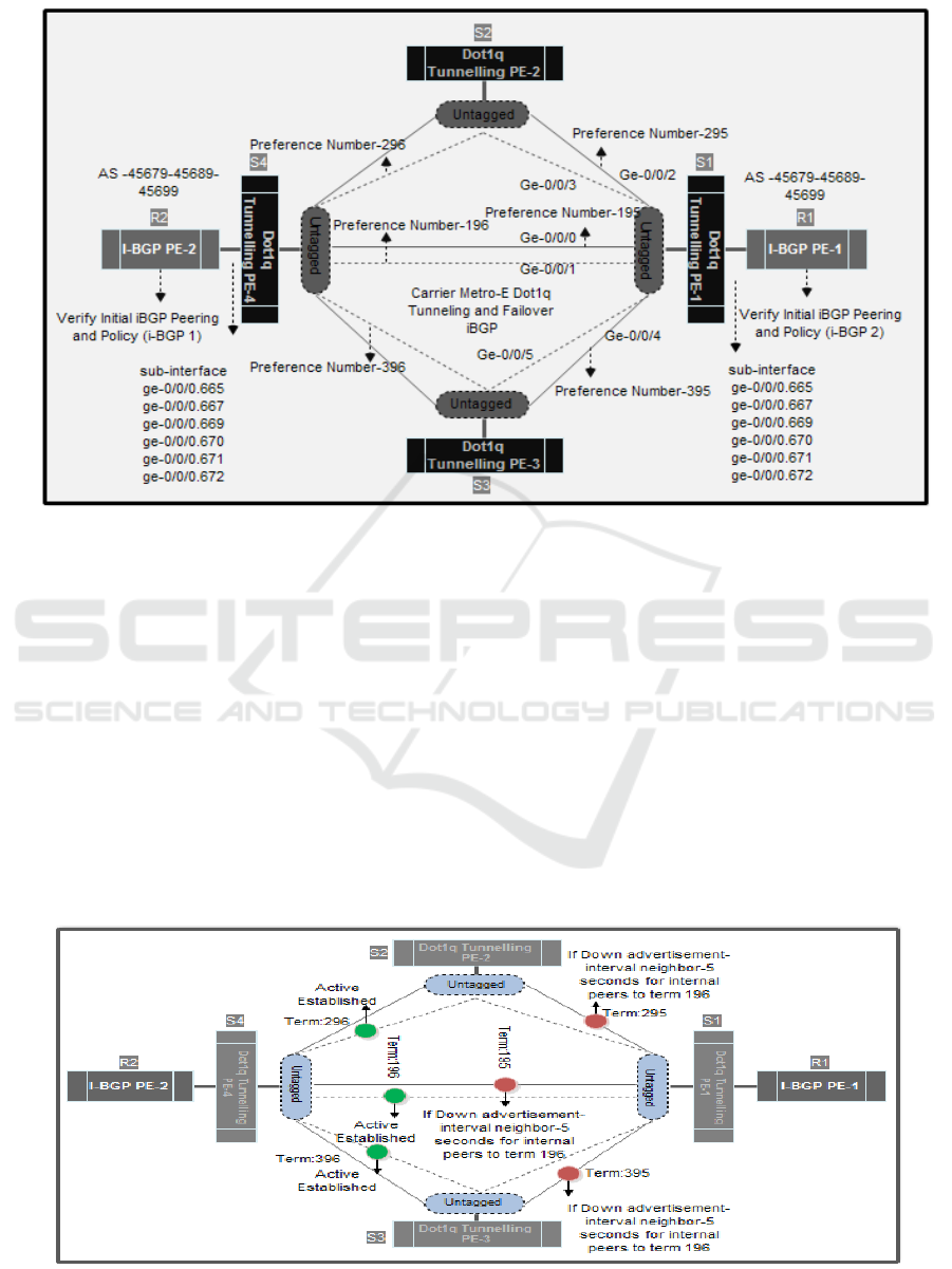
Figure 8: Integrated Internal BGP Provides Multi-Link Metro Dot1q Tunnelling Q-in-Q Environment Backhaul
4.1 Process Failover Functionality and
Recovery Schema
The research paper aims to provide specific results
and find out about how the failover function is
applied to backhaul, especially at ISPs, by applying
a combination of Layer 2 (Dot1q) and Layer 3 (I-
BGP). The process of testing and analyzing the
results of network failure on primary and secondary
links will be simulated by doing, on the interface
port Switch and sub-interface switches, namely ge-
0/0 / 0.665, ge-0/0 / 0.667, ge-0/0 / 0.669, ge-0/0 /
0.670, ge-0/0 / 0.671, ge-0/0 / 0.672. Several tests
can be done; in this paper, we test link failures in
failover techniques by sending echo reply (ICMP)
packets, deactivate the port (deactivate). The first
test step is the port (deactivate).
On the switch interface. The second test step issued
the command "shutdown or inactive" on a particular
network interface (interface Ge-0/0/0, Ge-0/0/1, Ge-
0/0/2, Ge-0/0/3, Ge-0/0/4, Ge-0/0/5). Both steps and
options, and the results will be explained in Ms.
Table. Excel and the results will be mapped in the
form of graphics. Two testing techniques are actual
when one link or interface node fails the secondary
link will make recovery. The table below shows the
procedure for simulating and performing link testing
and node failure and recovery.
Figure 9: I-BGP Fast Failover Functionality and Recovery
Scalable Resilient Internal BGP: Fast Recovery Mechanism Provide Multi-link Environment Carrier Ethernet Backhaul
203

The process of selecting a route for the next
failover will be based several parameters, is
destination-address (neighbor and peering) and the
value of the preferred term for each of which has
been explained as follows:
Procedure Failover Functionality and Recovery:
1. First Term: The IP Address P2P interface on
each router is an internal BGP peering to
select routing rules with specific values to the
destination address.
2. Second Term: IP router interface P2P address
IBGP will values in the preference parameters
of each routing rules, the smaller the
preference, the action will be used in the
routing process.
Table.2 will explain how the procedures for link
failure and node between testing processes (Primary
Link: Interface Port ge-0/0/0 ge-0/0/2- ge-0/0/4) and
recovery.
:configure
Entering configuration
mode
:deactivate interfaces
ge-0/0/0
:show interfaces ge-0/0/0
##
## inactive: interfaces
ge-0/0/0
##
description
Primary-Link-Preference-195
unit 0 {
family ethernet-switching
{
port-mode trunk
(tagged);;
vlan {
members;
}
}
}
:configure
Entering configuration
mode
:deactivate interfaces
ge-0/0/2
:show interfaces ge-0/0/2
##
## inactive: interfaces
ge-0/0/2
##
description
Primary-Link-Preference-295
unit 0 {
family ethernet-switching
{
port-mode trunk
(tagged);;
vlan {
members;
}
}
}
:configure
Entering configuration
mode
:deactivate interfaces
ge-0/0/4
:show interfaces ge-0/0/4
##
## inactive: interfaces
ge-0/0/4
##
description
Primary-Link-Preference-395
Config: interface unit 0 {
Config: family ethernet-
switching {
Mode: port-mode
trunking (tagged);
vlan {
members;
}
ICT4BL 2019 - International Conference on IT, Communication and Technology for Better Life
204

Table.3 Results of date and time of failover link implementation from primary link to secondary link
Link Date and
Time Failure
Status Status
Recovery
Date and
Time Recovery
Primary Link
(Term-195)
5/28/2019 8:00 ICMP
Timeout
Running
Preference 196
5/28/2019 8:02
Primary Link
(Term-295)
5/28/2019 8:00 ICMP
Timeout
Running
Preference 296
5/28/2019 8:02
Primary Link
(Term-395)
5/28/2019 8:00 ICMP
Timeout
Running
Preference 396
5/28/2019 8:02
The process of implementing failover link is
done by performing a failure response time, how
long the failure response time will be tested, and the
time the link used from the primary link (preference-
term 195) to the secondary link (preference-term
196). Dot1q interface on the link serves to channel
data traffic and other links as a backup if the main
link (195 preference) fails. In transferring and
testing the time of a failover response, it will be
tested how long the failover response is, or when the
data path is moved from the primary term to the
second term, with conditions, the primary term and
the second term will be active.
Procedure:
1. Send ICMP packages using the command
"PING and COUNT = 100" on R1 to
neighbors R2 as seen below, so that time
out can be seen.
ping detail 10.10.5.8 no-
resolve rapid count 100
2. To see term preference 195 R1 lines
(Primary Link) used to send ICMP
packets to R1, type the command:
-
traceroute (IP Address R1)
3. At the same time shutdown/Deactivate is
Primary Link (Term 195) as if the
Primary Link line is in a fault or fault
state that is used to send ICMP R2
packets with type command:
: configure
Entering configuration
mode
: deactivate interfaces
ge-0/0/0
:show interfaces ge-0/0/0
Status:
## inactive: interfaces
ge-0/0/0
##
description
Primary-Link- (Number
Preference-195)
config: unit 0 {
config: family ethernet-
switching {
port-mode trunk;
vlan {
members;
}
}
Seen in the output below, the ICMP packet
sending path from the primary link line (term-195)
which is 10.10.5.6 changes using the secondary link
(term 196) line 10.10.5.8.
Traceroute 10.32.0.35
Tracing route to 10.32.0.35over a maximum of
10 hops
1 1 ms 1 ms 1 ms 10.17.248.9
2 12ms 28ms 12ms 192.168.3.2
3 12ms 28ms 12ms 192.168.13.199
4 28ms 12ms 12ms 172.30.0.57
5 12ms 28ms 12ms 10.10.5.6
Trace complete.
Traceroute 10.32.0.35
Tracing route to 10.32.0.35over a maximum of
10 hops
1 1 ms 1 ms 1 ms 10.17.248.9
2 12ms 28ms 12ms 192.168.3.2
3 12ms 28ms 12ms 192.168.13.199
Scalable Resilient Internal BGP: Fast Recovery Mechanism Provide Multi-link Environment Carrier Ethernet Backhaul
205
4 28ms 12ms 12ms 172.30.0.57
5 12ms 28ms 12ms 10.10.5.10
Trace complete
At the same time, the PING command indicator
will be visible in R1, it looks like the output
command below. A packet loss occurs when there is
an automatic switching from Primary Link (Term
195) to Secondary Link (Term 196) due to a fault.
Then how long does it take to get to the track
ICMP packets can be sent back when they occur
fault recorded. In the test results, it appears that 2
hop packet loss occurs, meaning that the round trip
is 2 m/s.
4. Steps 1 to 3 are repeated for the primary
link (term 295), and primary link (term
395) and vice versa deactivate the
secondary link (term 296) and secondary
link (term 396).
5. EVALUATION RESULT AND
DISCUSSION FAILOVER
FUNCTIONALITY AND
RECOVERY
5.1 ∑ Latency (Primary Link and
Secondary Link)
Modeling and concepts that have been carried out
and collected, primary links and secondary links
with failover concepts and recovery times in each
test carried out, will monitor link traffic, such as
sending the echo reply package and peering session
process. Next will be seen based on time and date
when the primary link fails, or the secondary link
fails. Each activity will be explicitly analyzed on
each set of results at the time of failure.The
mechanism applied to the echo reply or the ICMP
protocol is based on when the primary path has a
link failure. Where the link or secondary link path
node will be automatically created the status of the
secondary link path will be active and idle, with the
concept of an internal BGP peering (i-BGP) session.
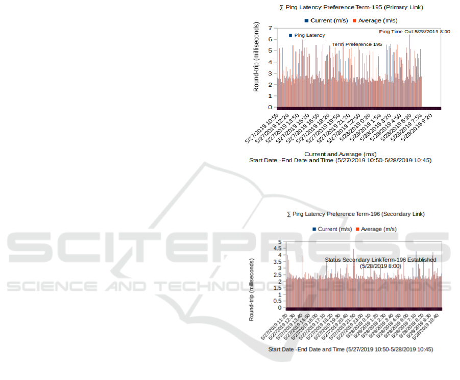
In figure 10, a test is performed, the average failure
time in the main link or on the primary link path.
The movement and recovery time process
concerning the time interval if there is a transition
state in the link will be logged in I-BGP. In figure 10
it clearly shows a direct correlation between the
average failure time, to send an echo reply or ICMP
packet on the primary link. In figure 11 the failure
time for the i-BGP peering session that is applied
with the waiting interval is 0-2, 0-5 seconds, that is,
by measuring 2 hop requests time out. So the fails
time on the primary link does not affect the backup
(secondary) link. When the main link fails, the link
will be connected or active (status established), a
secondary link will be created (status established).
Figure10. ∑ Ping Latency Term 195 Primary Link
(Failure Link 5/28/2019 8:00)
Figure11. ∑ Ping Latency Term 196 Secondary Link
(Recovery Link Established Status)
In an active steady-state, internal BGP will
exchange update package policies with neighbors. A
time delay will begin when receiving an update and
save the message, and the action is not set to zero. If
a link failure is found, a notification is sent to the
neighbor and then returns to standby session status.
So that the primary link to the secondary link does
not take too long for the recovery process. During
the process of transferring links to standby
conditions, it does not require time, it can be
interpreted as 0-2, 0-5seconds, or there is no packet
loss.
ICT4BL 2019 - International Conference on IT, Communication and Technology for Better Life
206

5.2 Data Rate Primary Link and Secondary ∑
(Receive Inbound dan Transmit Outbound)
Figure12. ∑ graph of traffic index data rate primary link
(process drop link)
Figure.12 above shows on 5/28/2019 at 8:00.
Incoming and outgoing traffic on the main
preference link 195 link recovery failures will
periodically create secondary intervals during the
recovery link process, the I-BGP gateway internal
link on the primary link will form sessions with P2P
IP addresses and will be called peer. The Border
Gateway Protocol uses the Finite State Machine
method in terms of maintaining all peer tables and
operational status. At the secondary link session, the
Internal BGP link will be set as an active-standby
status. The recovery process of the internal link
gateway border protocol will be created. Active
BGP internals will exchange routes through an
update message.
Figure13. ∑ graph of traffic index data rate secondary link
Figure 13 shows that at the equivalent time, the
primary link has a link failure, the status of the
secondary link is recovering (established).
6. CONCLUSION
The modeling and concepts that we integrate into
this paper are presenting and implementing a link
failure mechanism with rapid conditions in terms of
handling link fails and connecting congestion in the
Metro Datacom backhaul network, at layer 3 and
layer 2 by implementing peering on i-BGP sessions
with neighbors. In the concept method of failover
mechanism and network failure recovery using
internal BGP ad values, the value is 0 to 2, 0-5
seconds for internal peers. The value of distance in
preference then calculates the parameters of each
routing rule from the source to the destination, the
smaller the value (preference terms are 195, 295 and
395) in preference, the rules will be used or take
routing actions first. This preference value will
count continuously periodically as long as the link is
operational or inactive status. A path link for each
pair from source to destination and proactively
install the appropriate routing flow entries. When the
main link has a link failure, then each session
(neighbor) in i-BGP will return the link to the
secondary link. The results and modeling of the
results show that the average recovery time of
failure mechanisms in each link is significantly
faster to recover. The time and failure status of the
main link will not affect the secondary link. The
process that will experience when the main link has
a failure, the main link will be connected or active
(created) on the secondary link. The learning process
of the internal gateway protocol algorithm then
exchanges update packages with neighbors who are
interconnected. The next process is when the time
delay begins again when it will receive the update
process or save the message, and it will not be set to
zero. The process if an error or failure of the link is
rediscovered, the action will be taken, and the
notification sent to the active neighbor. Recovery
link from the primary path or link to the secondary
link will not require a long time; the link selection
process will be done randomly with the round-robin
algorithm. The failure transfer link to process will
not require time, it can be interpreted as a process of
0-2, 0-5 seconds, and there is no packet drop and
loss.
REFERENCES
Internet Content Provider "," [Online May, 2019]
.Available:https://www.sciencedirect.com/topics/comp
uter-science/internet-content-provider.
Scalable Resilient Internal BGP: Fast Recovery Mechanism Provide Multi-link Environment Carrier Ethernet Backhaul
207

Capitalizing on the Fast-Growing Ethernet Business
Services Market"," [Online May 2019].Available:
https://www.juniper.net/uk/en/solutions/metro/metro-
ethernet/.
Ruepp, S., Wessing, H., Zhang, J., Manolova, A. V.,
Rasmussen, A., Dittmann, L., & Berger, M. (2010).
Evaluating multicast resilience in carrier ethernet.
WSEAS Transactions on Circuits and Systems, 9(2),
101–110.
Bhor, M., & Karia, D. (2018). Network recovery using IP
fast rerouting for multi-link failures. Proceedings of
2017 International Conference on Intelligent
Computing and Control, I2C2 2017, 2018–January, 1–
5.
M. Ali, G. Chiruvolu, and A. Ge, (2005). Traffic
engineering in metro ethernet,” IEEE Netw., vol. 19,
no. 2, pp. 10–17.
R. Sofia, (2009). A survey of advanced ethernet
forwarding approaches,IEEE Commun. Surveys
Tutorials, vol. 11, no. 1, pp. 91–115.
Documentation Dot1q Tunneling and VLAN Translation
"," [[Online May, 2019].Available:
https://www.juniper.net/documentation]
Abu Hena Al Muktadir, Kenji Fujikawa, Hiroaki Harai,
"Route advertisement policies for border gateway
protocol with provider aggregatable addressing" High
Performance Switching and Routing (HPSR) 2016
IEEE 17th International Conference on, pp. 42-48,
2016.
Vissicchio, S., Cittadini, L., & Di Battista, G. (2015). On
iBGP Routing Policies. IEEE/ACM Transactions on
Networking, 23(1), 227–240.
Santhosh, S., Dakshayini, M., Tech, M., & Student, C. N.
E. (2016). Effect of Route Reflection on IBGP
Convergence and an approach to reduce convergence
time, 4(8), 4530–4535.
Border Gateway Protocol To Enhance Failover In
Multihoming Environment By Muhammed
Zaharadeen Ahmed A dissertation submitted in
fulfilment of the requirement for the degree of Master
of Science ( Computer and Information Engineering )
Kulliyyah of Engineering International Islamic
University Malaysia. (2017), (March).
Pelsser, C., Takeda, T., Oki, E., & Shiomoto, K. (n.d.).
Improving Route Diversity through the Design of
iBGP Topologies.
Mirkhanzadeh, B., Shakeri, A., Shao, C., Razo, M., Tacca,
M., Galimberti, G. M.,Fumagalli, (2018). A. An SDN-
enabled multi-layer protection and restoration
mechanism.
S. Antonakopoulos, Y. Bejerano, and P. Koppol, (2015)
“Full protection made easy: the dispath ip fast reroute
scheme,” IEEE/ACM Transactions on Networking
(TON), vol. 23, no. 4, pp. 1229–1242.
Shukri, A., Noor, M., & Mat, M. (2013). Fail-stop failure
recovery in neighbor replica environment. Procedia -
Procedia Computer Science, 19, 1040–1045.
Lin, Y.-D., Teng, H.-Y., Hsu, C.-R., Liao, C.-C., & Lai,
Y.-C. (2016). Fast failover and switchover for link
failures and congestion in software defined networks.
2016 IEEE International Conference on
Communications.
L. D. Swapnil R Sharma Dikshit, (2014) “Implementing
an algorithm to enhanced protection for routing in IP
networks,” in Advanced Research in Computer
Engineering and Technology (IJARCET), 2014 IEEE.
IEEE, pp. 1916–1920.
Peer, A. M., & Registration, C. (2007). A Transparent
Failover Mechanism for a Mobile Network with
Multiple Mobile Routers, 11(7), 604–606.
Dwyer, J., & Jasani, H. (2013). An Analysis of
Convergence Delay Caused by Link Failures in
Autonomous Systems, 1–6.
Usino, W., Damanik, H. A., & Anggraeni, M. (2019).
Improving Internal BGP Provide Fast Failover in
Multihoming Environment Mobile Backhaul. Journal
of Physics: Conference Series, 1201, 12016.
ICT4BL 2019 - International Conference on IT, Communication and Technology for Better Life
208
