
Application Research of Single-chip Microcomputer in Intelligent
Car Key System
Zhu Liu
1, a
1
Sichuan Vocational and Technical College, Suining 629000, China
Keywords:
Safety car lock, remote identification of car theft prevention, encryption, wireless communication,
alarm
.
Abstract:
In order to better enhance the anti-theft system of automobiles, STM32 is taken as the research
object and STM32 as the controller. The central module controller generates random code as the
password address, which is sent to the key module by wireless mode. The key module sends back
the encrypted information according to the address. The central module decrypts and verifies the
encrypted information, and returns the result of verification. The result of the experiment decides
whether to carry out acousto-optic alarm or not; after unlocking, the central module can change
the encryption method and password; the random password is stored by EEPROM, and the
password information is not lost when the system is powered down, and the password
information cannot be changed or leaked by wireless remote control. The system uses the
wireless communication chip CC1100E to communicate with STM32 single-chip microcomputer,
which effectively improves the technical achievement. The security of automobile anti-theft
system has been tested and debugged many times. It is found that the system is stable and has
played an important role in the improvement and progress of automobile anti-theft system
.
1 INTRODUCTION
With the continuous improvement of people's living
standards, automobiles have increasingly become an
indispensable part of people's lives. The number of
cars is increasing, and the number of stolen vehicles
is also increasing year by year, which brings great
instability factors to the society. The safety of cars is
one of the most concerned problems for drivers. At
present, there are four kinds of car theft-proof
devices at home and abroad, which are mechanical,
electronic, chip and network-type. Electronic theft-
proof is the most widely used way of theft-proof. Its
theft-proof system only realizes one-way
communication, and its encryption method is simple
and easy to be intercepted and cracked. Therefore,
chip-based digital anti-theft and network anti-theft
become the development direction of automobile
anti-theft technology.
Two-way synchronization automobile anti-theft
system mode of STM32 single-chip microcomputer
uses wireless communication chip CC1100E and
STM32 single-chip microcomputer to communicate
through SPI mode. Its wireless communication and
random encryption way achieve further upgrading of
the automobile anti- theft system, and in this way of
wireless communication, the two- way
communication between the key module and the
central module of the automobile is realized. Its
advantages of two-way verification, synchronization
of encryption and high security of password
information provide strong technical support for the
updating of automobile anti-theft system. Although
the structure of STM32 microcontroller encryption
is complex, it is easy to operate for users.
Beginning with the introduction of STM32
single-chip automobile anti-theft system, the design
scheme of its software and hardware is elaborated,
and the way and method of remote identification of
automobile anti-theft intelligent system operation are
described. Through repeated tests by technicians, it
proves that STM32 single-chip has stable "two-way,
simultaneous and consistent" communication
technology, and its chip-based digital anti-theft and
the use of random passwords solves people's worries
about password leakage, and lays a theoretical
support for the installation of STM32 single-chip
automobile anti-theft system at home and abroad.
Liu, Z.
Application Research of Single-chip Microcomputer in Intelligent Car Key System.
DOI: 10.5220/0008873401210127
In Proceedings of 5th International Conference on Vehicle, Mechanical and Electrical Engineering (ICVMEE 2019), pages 121-127
ISBN: 978-989-758-412-1
Copyright
c
2020 by SCITEPRESS – Science and Technology Publications, Lda. All rights reserved
121

2 METHODOLOGY
The overall structure of STM32 system is composed
of two modules: central module and key module. As
shown in Figure 1, the central module of STM32
system is installed on the car body, while the key
module is installed on the smart key. The two
modules communicate by wireless two-way way.
Among them, the central module has realized the
functions of decryption, verification and password
modification, while the key has realized the function
of switch lock (Kim T, Jin B, Cha S H, et al, 2017;
Kotb A O, Shen Y C, Zhu X, et al, 2018).
Central
Module
Circuit
Key
Module
Circuit
1. Send boot codes
2. Send Random
Address
3. Send Encrypted
Information
4. Return the check
results
Figure 1. Overall structure diagram of automobile anti-
theft system.
In STM32 system, when the circuit starts to work,
both modules will be in a state of waiting to receive
signals. The central module waits for the switch lock,
while the key module waits for the central module to
send the relevant information of the vehicle
condition. Two circuit modules will set the same
password, and each password will have a different
address. The main key module will ask the central
module if it can open the lock, then the central
module will send a random eight-digit random
address and the key module will find the
corresponding password according to the received
address. At the same time, after encryption, it is sent
back to the central module, the central module will
verify it and the relevant indicator switch locks will
be made only when it passes the verification (Trope
R L, Smedinghoff T J, 2018; Woo S, Jo H J, Lee D
H., 2015).
3 RESULTS AND DISCUSSION
The software and hardware of STM32 single-chip
automobile anti-theft system adopt the optimal
processing performance. The hardware circuit is
mainly dominated by the smallest system of STM32
single-chip microcomputer. It includes four modules:
power supply, wireless communication circuit,
memory chip circuit and LCD (liquid crystal display)
display circuit (Atif Y, Ding J, Jeusfeld M A, 2016).
As a main controller, STM32 single-chip
microcomputer combines different modules to form
a complete and stable circuit network, as shown in
Figure 2.
The software design of the system is to realize
the wireless communication between the central
module and the key module. The central module
uses a timing tracker to generate the corresponding
random codes, which are sent to the key module by
wireless communication (Werle M, Will P,
Hülshorst T, et al, 2016; Matthews V O, Uzairue S I,
Noma-Osaghae E, et al, 2018). The random code is
the address corresponding to the password, and the
address received by the key module needs to query
the corresponding password from EEPROM, and
then encrypt and send it to the central module after
the query action is completed (Walter A, Finger R,
Huber R, et al, 2017), which effectively prevents
illegal elements eavesdropping and theft. At the
same time, each address is different, representing
that the corresponding eight-digit digital password is
also different, which better enhance the car's anti-
theft function (Kim C, Shin D, Shin D, et al, 2016,
as shown in Figure 3.
3.1 System Hardware Design
STM32F103VET6 is used as the main controller,
and STM32F103VET6 is a 32-bit MCU based on
ARM Cortex-M3 core produced by STM Company.
Its working frequency can be as high as 72M, which
is three or four times faster than the processing
speed of general single-chip microcomputer such as
8/16 units. STM32 has a beautiful design, and Flash
can be programmed internally. It also has 64KB
internal RAM, 3 SPI interfaces and 5 UART
interfaces, which fully meets the functional
requirements of the main controller (Li Z, Pei Q,
Markwood I, et al, 2018).
The first module in the hardware is the voltage
stabilized power supply circuit. The corresponding
working voltage of STM32 SCM is about 5V. As we
all know, the power sources of batteries usually used
do not reach 5V. The main reason for the realization
of this system is that a voltage stabilized power
supply circuit is designed. The chip supporting the
voltage stabilized power supply circuit is L7805.
The input voltage range of L7805 is between 6V and
21V. At the same time, two capacitors are connected
at the input and output of chip L7805. The purpose
is to consider the ripple and reduce the influence of
ripple on the voltage. In this way, the working
voltage of the wireless communication chip is
ICVMEE 2019 - 5th International Conference on Vehicle, Mechanical and Electrical Engineering
122
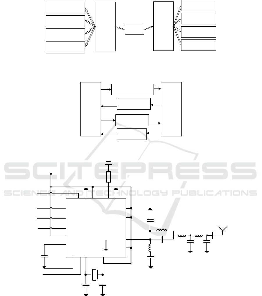
maintained at 3.3V, and the L7805 is regulated by 3.3V, which will better achieve this measure.
Regulated power
supply
Alarm circuit
Storage circuit
LCD
Central
Control
Minimum
System
Regulated power
supply
Alarm circuit
Storage circuit
LCD
Key
Module
Minimum
System
wireless
Figure 2. Hardware circuit diagram of automobile anti-theft system.
Central
module
Key
module
wireless
communication
Timer 0 generating
random code
Send back the
encrypted code
Send a new
password
Send back the
check code
Figure 3. System software architecture block diagram.
CC1101
AVDD 15
AVDD 14
AVDD 11
RF-N13
RF-P12
1.SCLK
2.SO(GDO1)
3.GDO2
4.DVDD
5.DCOUPL
DIE ATTACH PAD
C131
L131
L121
C124
C121
L122
C122
L123
C123
C125
Antenna
(50 Ohm)
XTAL
C101C81
R171
1.8V-3.6 power supply
SI
SO
(GDO1)
GDO2
optional
C51
GDO0
(Optional)
CSn
Figure 4. Circuit schematic diagram of wireless communication module.
The second module of hardware is wireless
communication chip circuit. The system uses
CC1101, a wireless transceiver chip, to adjust its
working frequency to 433M, and connects it to
STM32 microcontroller by SPI communication
mode. At the same time, only four lines are needed.
When CC1101 is configured, two additional lines
are needed, such as GDO0 and GDO2 in Figure 3.
The third module of hardware is alarm circuit.
The alarm system mainly uses sound and light.
Among them, LED backfilling is used. When the
single-chip has high-level output, LED is not bright;
Application Research of Single-chip Microcomputer in Intelligent Car Key System
123

when it is low-level output, LED will be bright.
Sound generation is driven by pulses, and a NPN
transistor is used to control the corresponding
switching on and off. As long as STM32 single-chip
microcomputer gives the base of the transistor a high
level, it will turn on and turn off the low level. The
horn vibration between the turn-on and turn-off can
produce the corresponding sound, and the frequency
of this sound will also produce different sounds
according to the different pulses, so as to achieve the
purpose of alarm.
The fourth module of hardware is memory chip
circuit. This system uses AT24C02 produced by
Atmel Company, which is 256 bytes EEPROM.
STM32 single-chip microcomputer communicates
and controls AT24C02 through I2C mode. The two
lines SDA and SCK are connected by clock line and
data line, respectively. I2C bus can be connected
with multiple devices simultaneously, and the
relationship between the devices is a line, which
requires an additional 4.7K pull-up resistance.
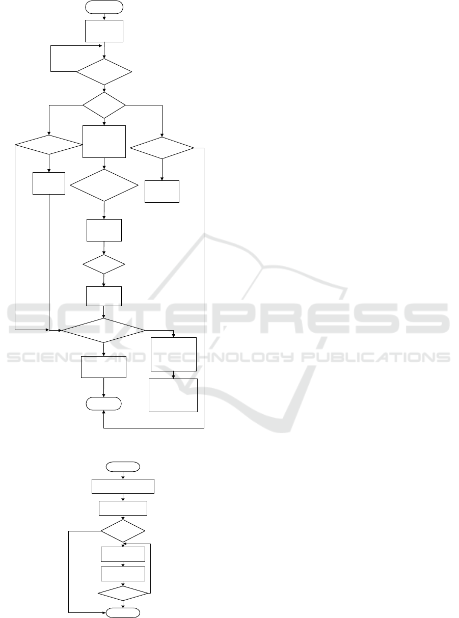
3.2 System Software Design
As the main controller, STM32 single-chip
microcomputer connects various functional modules
and achieves various functions. The flow charts of
the two modules are shown in Fig. 5 and Fig. 6,
respectively.
In the system software design, the central module
generates the corresponding random code by timer
and sends it to the key module by wireless way. The
random code is the corresponding address of the
password, and the key module inquires the password
from EEPROM after receiving the address, and then
returns to the central module after encrypting. Each
address is different, because the password and
encryption methods are not public, leading to the
theft cannot be verified. At the same time, in order
to ensure the consistency of the passwords of the
two modules, for each new password issued by the
central module, the key module needs to return a
check code to ensure the consistency of the
passwords of the central module and the key module.
First of all, the generation of random codes is
introduced. The random code generated by the
central module circuit is the address of EEPROM.
As mentioned above, EEPROM is 256 bytes, and its
starting address range is between 0 and 255. There
are 256 storage units, so the corresponding timer 0 is
set to the corresponding mode 2, and the initial
count value is set to 0, that is, the counting range is 0
to 255, which is exactly the same as the address of
EEPROM.
When the system program starts to operate, the
timer 0 has been set up and started to time. The
timer will jump randomly in the range of 0-255.
After receiving the corresponding signal sent from
the key module, it will randomly take out the value
of the current location. After taking one, it will take
another one after prolonging a period of time, so that
eight digits can be taken consecutively, and the
delay between values of each number depends on
the first number obtained. The flow chart is shown
in Figure 7
start
Receive the
signal?
Boot
code?
Receive the
signal?
Correct?
Change Password?
Lock the car?
Call the
police?
Return
System
initial
Lock the
car
Send out
random
codes
Call the
police
Decrypt,
verify
Unlock
Change
Password
Modify the
encryption
method?
Modify the
encryption
method?
Figure. 5 Main program flow chart of central module
circuit
ICVMEE 2019 - 5th International Conference on Vehicle, Mechanical and Electrical Engineering
124
start
Send a
signal?
Boot
code?
Receive the
signal?
Correct?
Change Password?
Lock the car?
Call the
police?
Return
System
initial
Lock the
car
Send out
random
codes
Call the
police
Decrypt,
verify
Unlock
Change
Password
Modify the
encryption
method?
Modify the
encryption
method?
Figure 6. Main program flow of key module circuit.
Start
Received
signal
Eight?
Return
Timer 0, mode 2
Start timing
Take (TL0)
Delay(TL0)
Figure 7. Flow chart of random code generation.
In two-way wireless communication program
design, the wireless communication chip CC1100E
communicates with STM32 MCU by SPI. After
CC1100E is properly configured, in a received
subroutine INT8U halRf Receive Packet (INT8U *
rxBuffer, INT8U * length), if it receives a signal, it
will return a '1'. If it does not receive a signal, it will
return a '0'. Through different return values, it is
possible to judge whether the signal is received. If
the signal is received, read the corresponding data. If
it receives a signal, it calls halRfReceivePacket ()
and returns a '1', and then reads and receives the
corresponding data in the RxBUF [] array. After the
central module circuit sends out the signal, the key
module must wait for the received signal, because
the signal disappears as soon as it is sent out.
Similarly, when the key module transmits the signal,
the central module also needs to wait for reception.
The procedure of password modification and
verification in software design is as follows: the
owner can modify the password after unlocking,
while the password modification needs wireless
communication to keep the password of the central
module and the key module consistent. With this
premise, the owner will modify the password from
the central module after unlocking, rather than
through the remote terminal, so as to better ensure
the security of the password. In addition, when
modifying the password, the corresponding
confirmation from the key module is needed. Only
when the host receives the confirmation signal from
the key module, the corresponding password
modification operation will begin.
When the above operation is completed, the
central module will synchronize the corresponding
password information to the key module. 512
passwords are sent 64 times, 8 passwords each time.
The key module can only receive eight cipher
numbers at a time, and after the key module
successfully receives eight ciphers sent by the
central module, the key module will send the data to
the central module as it is, thus ensuring that the
information key module sent by the central module
is normally received. Such return information is also
the beginning of the next group of ciphers sent by
the central module. The specific procedure flow is
shown in Figure 8.
In addition, when the key module receives the
password, it needs to cooperate perfectly with the
central module in time. That is to say, the central
module sends the information, the key module goes
out to accept the status, and the key module returns
the information. The central module also needs to be
in the state of waiting for acceptance, and only in
Application Research of Single-chip Microcomputer in Intelligent Car Key System
125

this way can the corresponding password
modification operation be completed. The program
flow chart is shown in Figure 9.
start
Sixty-
four?
Return
Is the check
correct?
Generating
random codes
Write to
EEPROM
Read
password
Figure 8. Synchronization password flow chart between
central module and key module
start
Received
signal
The Eight?
Return
Timer 0, mode 2
Start timing
Take (TL0)
Delay(TL0)
Figure 9. Key Module Receiving Password Procedure
Flow Chart.
3.3 System Performance Test
After many experiments, the circuit system has
realized bidirectional communication between
wireless modules. The key module has realized the
function of switch lock, while the central module has
realized the function of decrypting, verifying and
opening the vehicle. At the same time, the function
of modifying the password has been added. Next,
the results of the switch lock test of STM32 MCU
system are verified by two tables.
Table 1. Open Lock Test Statistics.
Total number of
unlocks
Total number of
successful unlocking
5 5
11 11
16 15
20 20
25 24
32 31
Table 2. Closure Test Statistics.
Total number of
lockouts
Total number of
successful lockouts
5 5
11 11
16 16
20 20
25 25
32 32
From the table, it is easily found that the anti-
theft system of STM32 has high success rate, stable
performance and certain practicability, but
occasionally there will be one or two errors. This
phenomenon occurs because the wireless
communication will be disturbed by electromagnetic
waves in the environment, resulting in the
communication interruption between the central
module and the key module. However, STM32 SCM
anti-theft system can adjust the communication
between them by changing the direction of remote
control.
4 CONCLUSION
By exploring STM32 single-chip technology, the
comprehensive improvement of automobile anti-
theft has been successfully realized through a certain
way of satellite communication, and the two-way
communication between the key module and the
central module of the automobile is realized. In
summary, STM32 single-chip technology has the
following characteristics: First, two-way verification.
When the key module sends encrypted information,
the central module checks the encrypted information
and sends back the results of the checking, and also
ICVMEE 2019 - 5th International Conference on Vehicle, Mechanical and Electrical Engineering
126

carries out corresponding instructions according to
the results. Second, the synchronization of
encryption mode is realized. The central module of
STM32 MCU technology can change the secret and
change the encryption mode after unlocking, and
this operation is carried out by wireless
communication, thus realizing the synchronization
of encryption mode. Third, password information
has high security. STM32 single-chip
microcomputer technology uses EEPROM to store
random passwords. When the system is out of power,
the password information will not be lost or leaked
through wireless communication, which greatly
improves the safety of the car and anti-theft system.
After a lot of testing and verification, the
performance of this technology is good. The next
step is to study how to improve the encryption mode
of the system and how to reduce the electromagnetic
interference of the system.
REFERENCES
Atif Y, Ding J, Jeusfeld M A. Internet of things approach
to cloud-based smart car parking. Procedia Computer
Science, 2016, 98, pp.193-198.
Kim T, Jin B, Cha S H, et al. Secure Vehicle Pseudonym
Certificate for Smart Car in Internet of Vehicles.
International Journal of Control and Automation,
2017, 10(6), pp. 35-48.
Kim C, Shin D, Shin D, et al. Secure protection of video
recorder video in smart car. International Journal of
Distributed Sensor Networks, 2016, 12(12), pp.
1550147716681792.
Kotb A O, Shen Y C, Zhu X, et al. iParker—A new smart
car-parking system based on dynamic resource
allocation and pricing. IEEE transactions on
intelligent transportation systems, 2016, 17(9), pp.
2637-2647.
Li Z, Pei Q, Markwood I, et al. Location Privacy Violation
via GPS-Agnostic Smart Phone Car Tracking. IEEE
Transactions on Vehicular Technology, 2018, 67(6),
pp. 5042-5053
Matthews V O, Uzairue S I, Noma-Osaghae E, et al.
Design and Construction of a Smart Wireless
Access/Ignition Technique for Automobile.
International Journal for Research in Applied Science
& Engineering Technology, 2018, 6(8), pp. 165-173.
Trope R L, Smedinghoff T J. WHY SMART CAR
SAFETY DEPENDS ON CYBERSECURITY.
Scitech Lawyer, 2018, 14(4), pp. 8-13.
Woo S, Jo H J, and Lee D H. A practical wireless attack
on the connected car and security protocol for in-
vehicle CAN. IEEE Transactions on intelligent
transportation systems, 2015, 16(2), pp. 993-1006.
Werle M, Will P, Hülshorst T, et al. Open Service
Platforms for the Smart Car. ATZ worldwide, 2016,
118(5), pp. 54-59.
Walter A, Finger R, and Huber R, et al. Opinion: Smart
farming is key to developing sustainable agriculture.
Proceedings of the National Academy of Sciences,
2017, 114(24), pp. 6148-6150.
Application Research of Single-chip Microcomputer in Intelligent Car Key System
127
