
New Method for Initial Alignment of Angular Sway Base based on
b-n Solidification Frame
Huaipeng Wang
1, a, *
, Yuanwen Cai
1, b
, Chaojun Xin
1, c
, Chen Yang
1, d
and Meiling Shi
1, e
1
Space Engnineering University, Beijing 101400, China
e
molihappl@126.com
Keywords: Angular Sway Base, Initial Alignment, Analytical Coarse Alignment, Solidification Frame.
Abstract: In this paper, for the problem of initial alignment process of strapdown inertial navigation system under the
angular sway base solved by the analytical alignment method has a large error. A component is proposed to
track the gravity vector at different moments in the navigation frame and the body frame. Take the
components of different two moments as the coarse alignment method of the new double vector positioning.
The simulation method is applied to verify that this method has the same effect as the traditional analytical
alignment method under static base. The result is obviously superior to the traditional analytical alignment
under the condition of angular sway base, and has stronger applicability.
1 INTRODUCTION
The initial alignment technique is the first step in the
navigation and positioning of Strapdown Inertial
Navigation System. Subsequent navigation can be
accurate only if the initial alignment is guaranteed to
be high precision (Y. Y. Qin, 2009). Generally, the
initial alignment can be divided into two processes:
coarse alignment and fine alignment (N.S. Reddy
and J. Murray, 1991). The coarse alignment is the
principle of using the double vector attitude to
determine the attitude angle at the initial moment.
Fine alignment is the use of Kalman filtering and
other techniques to achieve the initial attitude
misalignment angle estimation. Many scholars are
working on the study of coarse alignment. In the
paper (L. Schimelevich, et.al, 1996), using a neural
network based on multilayer perceptron in correct
the alignment and calibration errors of the inertial
measurement unit. Coarse alignment method has
been stated in detail in (D. H. Titterton and J. L.
Weston, 2004) under the heading of ground
alignmentmethods. Autonomous alignment method
mentioned in (O. Tekinalp and M. Ozemre, 2001)
also starts with the coarse alignment method. In the
paper (H. Y. Zhao, 2011), the accuracy of six
analytical coarse alignment modes is compared, and
finally the coarse alignment mode with the highest
precision is obtained.
The traditional analytical coarse alignment
method has better accuracy under static base.
However, under the condition of the angular sway
base, the angular sway will cause the gyro output
error to be large, consequently the alignment
accuracy will be affected. Therefore, the research of
coarse alignment technology of strapdown inertial
navigation system under the condition of angle
swaying base is of great significance.
Inspired by the paper (K. S. Yan and Y. L. Liu,
2017; J. Li, Y. Wang, Y. Li and J. Fang, 2018), an
initial alignment technique based on b-n
solidification frame for angular sway base is
proposed. And compare the traditional analytical
alignment method by simulation, this method can
effectively shield the angular swaying from the
initial alignment precision interference, can
effectively suppress the influence of the angular
sway on the roll angle precision, and greatly
improve the accuracy of the initial alignment.
2 THE PROBLEM OF
ANALYTICAL COARSE
ALIGNMENT
The analytical alignment is mainly obtained by
obtaining the component of the earth's rotation
angular velocity ωie and the gravitational
Wang, H., Cai, Y., Xin, C., Yang, C. and Shi, M.
New Method for Initial Alignment of Angular Sway Base based on b-n Solidification Frame.
DOI: 10.5220/0008872402350243
In Proceedings of 5th International Conference on Vehicle, Mechanical and Electrical Engineering (ICVMEE 2019), pages 235-243
ISBN: 978-989-758-412-1
Copyright
c
2020 by SCITEPRESS – Science and Technology Publications, Lda. All rights reserved
235

acceleration g in the body frame and the navigation
frame (Wang Xinlong, 2013), the alignment matrix
is obtained by the conversion relationship between
the two frames. The principle is as follows:
n
b
nb
gCf
(1)
n
in
b
n
b
ib
C
(2)
Where
T
n
gg 00
,
T
ieie
n
in
LL sincos0
.
A new vector can be constructed by the formulas
(1) and (2)
)(
n
inn
b
n
b
ibb
gCf
(3)
According to the above three formulas, the
alignment matrix can be found.
333231
232221
131211
1
CCC
CCC
CCC
f
f
g
g
C
b
ibb
b
ib
b
n
inn
n
in
n
n
b
(4
)
From the relationship between the alignment
matrix and the attitude angle, the attitude angle can
be expressed as
g
f
C
b
y
arcsinarcsin
32
(5)
b
z
b
x
f
f
C
C
arctanarctan
33
31
(6)
LL
g
f
ff
g
L
C
C
ie
b
iby
b
y
b
x
b
ibz
b
z
b
ibx
ie
sectan
)(
sec
arctanarctan
22
12
(7
)
When the pedestal has an angular sway, the
output of the accelerometer has almost no effect.
However, the output of the accelerometer will be
greatly disturbed, and the output of the
accelerometer will have a large error. Therefore, the
angular sway has less influence on the heading angle
and the pitch angle, and has a greater influence on
the roll angle.
3 ANGULAR SWAY BASE
COARSE ALIGNMENT NEW
METHOD
Under the static base, the traditional analytical
coarse alignment can obtain the initial attitude
information of the carrier relatively accurately
according to the gravity vector g and the earth
rotation angular velocity ωie, which can meet the
requirements of fine alignment conditions. However,
in actual situations, the Strapdown Inertial
Navigation System will be subject to angular sway
interference. If the analytical alignment method is
also used, it is difficult to meet the precision
alignment requirements. According to the principle
of double vector positioning, two mutually
uncorrelated vectors are determined. Since the
gravity vector is constantly changing in the inertial
space, the gravity acceleration at different times can
be selected to construct the double vector., Thus, the
double vector positioning is completed, which is the
coarse alignment method of the solidification frame.
In this paper, a coarse alignment algorithm based on
b-n (body frame and navigation frame) solidification
frame is proposed. The principle is as follows:
According to the chain rule (L. B. Chang, J. S. Li
and S. Y. Chen, 2015)
0
0
)0()(
b
b
n
b
n
n
n
b
t
t
CCCtC
(8)
In the formula, n0 and b0 are the inertial frames
formed by solidification of the n-frame and b-frame
at the initial timing of alignment.
0
t
n
n
C
and
0
b
b
t
C
respectively describe the attitude change of the n-
frame and the b-frame during the [0, t] time in the
alignment process, and can be obtained by the
following differential equation:
n
in
n
n
n
n
tt
CC
00
(9)
b
ib
b
b
b
b
tt
CC
00
(10)
Where
b
ib
is the angular rate of the carrier itself
measured by the gyroscope in the body frame.
ICVMEE 2019 - 5th International Conference on Vehicle, Mechanical and Electrical Engineering
236

n
en
n
ie
n
in
, Where
e
in
represents the earth's
rotation rate relative to the inertial coordinate
system,
n
en
represents the angular rate of the
navigation coordinate system relative to the earth
coordinate system. In addition, it can be easily
observed that the initial conditions of the above
differential equation are unit matrices. Therefore,
0
n
n
t
C
and
0
b
b
t
C
can be obtained by the following
equivalent rotation vector method.
n
in
represents the component of the Earth's
rotation angular velocity in the navigation
coordinate system, which can be expressed as
L
L
ie
ie
n
in
sin
cos
0
(11)
It can be seen that
n
in
is an amount that does not
change with time. When the time interval is T, the
equivalent rotation vector can be used to find that
the equivalent rotation vector can be expressed as
n
inn
T
(12)
2
2
)(
)cos(1)sin(
1
n
n
n
n
n
n
n
n
IC
t
t
(13)
10
1
0
t
ttt
n
n
n
n
n
n
CCC
(14)
And
b
ib
is measured by a gyroscope, which is a
quantity that changes with time. When the time
interval is T, the equivalent rotation vector can be
approximated as
2121
3
2
b
(15)
2
2
)(
)cos(1)sin(
1
b
b
b
b
b
b
b
b
IC
t
t
(16)
10
1
0
t
ttt
b
b
b
b
b
b
CCC
(17)
Where ‘×’ represents a cross multiplication
operation, and Δθ1 and Δθ2 can be obtained by the
following equation
dt
T
b
ib
2
0
1
(18)
dt
T
b
ib
T
2
2
(19)
)0(
n
b
C
is the transformation matrix of the initial
time carrier coordinate system to the navigation
coordinate system, and the matrix is a constant
value, which can be obtained by the method of
double vector positioning. However, the traditional
method of double vector positioning is due to the
shaking of the pedestal, resulting in a large output
error of the gyroscope, so using the tracking gravity
vector, that is, the components of the gravity
acceleration at different moments in the b-frame and
the n-frame at the initial moment are selected as the
double vector for the fixed posture. This method can
effectively shield the influence of angular sway on
the initial alignment accuracy.
According to the definition of the inertial
navigation frame, when the earth is in the process of
rotation, the component of the gravitational
acceleration g in the navigation frame is
g
g
n
0
0
t
(20)
Then transform the component of gravity
acceleration g in the navigation frame into the
component in the inertial navigation frame, which
can be expressed as
t
tt
n
n
n
n
n
gCg
00
(21)
The component of the gravitational acceleration g in
the body frame can be obtained by an accelerometer
z
y
x
b
b
b
b
f
f
f
f
(22)
Then convert it into the component of the inertial
body frame to get
t
tt
b
b
b
b
b
fCf
00
(23)
New Method for Initial Alignment of Angular Sway Base based on b-n Solidification Frame
237

According to the force equation, when the linear
interference of the carrier is neglected
00
0)(
n
b
nb
gCf
(24)
For the different moments of the formula (24),
there are time t1 and t2
0
1
0
1
)0(
n
n
b
n
b
b
tt
gCf
(25)
0
2
0
2
)0(
n
n
b
n
b
b
tt
gCf
(26)
You can get the formula (25) and (26) by
multiplying
))(0()(
0
2
0
1
0
2
0
1
n
n
n
n
b
n
b
b
b
b
tttt
ggCff
(27)
After transposing the formulas (25), (26), and
(27) respectively, the shift items can be obtained.
T
b
b
b
b
T
b
b
T
b
b
T
n
n
n
n
T
n
n
T
n
n
n
b
tt
t
t
tt
t
t
ff
f
f
gg
g
g
C
)(
)(
)(
)(
)(
)(
)0(
0
2
0
1
0
2
0
1
0
2
0
1
0
2
0
1
-1
(28)
The solution to
)0(
n
b
C
can be solved by the
appeal method, however, during the initial alignment
of the actual strapdown inertial navigation.
Measurement data is obtained through inertial
components, it is inevitable that there will be noise
interference during the measurement process. In
order to effectively block noise without losing
information, Integrate
0
b
b
t
f
and
0
b
b
t
f
at time [0, t]
respectively.
00
)0(
n
b
nb
VCV
(29)
In the same way, take two different moments t1
and t2, then
11
)0(
tt
n
b
nb
VCV
(30)
22
)0(
tt
n
b
nb
VCV
(31)
))(0(
2121
tttt
nn
b
nbb
VVCVV
(32)
So matrix A can be solved by (33)
T
bb
T
b
T
b
T
nn
T
n
T
n
n
b
tt
t
t
tt
t
t
VV
V
V
VV
V
V
C
)(
)(
)(
)(
)(
)(
)0(
21
2
1
21
2
1
1
(33)
t
b
V
And
t
n
V
can be accurately obtained by the
formulas (34) and (35)
dtfCdtfV
t
tt
t
b
t
b
b
t
b
b
b
00
00
(34)
dtfCdtfV
t
tt
t
n
t
n
n
t
n
n
n
00
00
(35)
And then can be converted to a recursive formula
(Y. X. Wu and X. F. Pan, 2011)
)(
3
2
)()(
2
1
2121212121
0
1-
vvvvvvCVV
b
b
bb
t
tt
(36)
t
t
tt
n
n
in
n
n
nn
g
T
TICVV
2
2
0
1
(37)
3 SIMULATION VERIFICATION
AND RESULT ANALYSIS
In order to verify this new method, this paper uses
Matlab to simulate this, and the simulation
conditions are set to: the position of the strapdown
inertial navigation system is 118° east longitude,
32.2° north latitude; T=0.01s; the total simulation
time is 2000s; the attitude angle of static base is
Ψ=2°, θ=3°, γ=4°. The constant drift of the
gyroscope is 1×10⁻³g, the random drift is 5×10⁻⁴g,
the constant value drift of the accelerometer is
0.02°/h, and the random drift is 0.01°/h.
The angular sway causes the attitude angle to
appear periodically:
76
2
cos4
45
2
cos3
37
2
cos2
t
t
t
(38)
ICVMEE 2019 - 5th International Conference on Vehicle, Mechanical and Electrical Engineering
238

The simulation results under static pedestal
conditions are shown in Fig.1, it can be seen that the
traditional analytical alignment under the static
pedestal condition is basically consistent with the
initial alignment technique based on the b-n
solidification frame proposed herein. The theoretical
attitude angles are the heading angle θ=3°, the pitch
angle γ=4°, and the roll angle Ψ=2°. Due to the
static pedestal conditions, the traditional analytical
alignment can be better adapted. However, the
proposed method is very close to the theoretical
value under static pedestal conditions, indicating that
the method can also have good alignment effect
under static pedestal conditions. However, due to the
constant value drift and random drift of the inertial
element itself, the result fluctuates around the
theoretical result. The new method proposed in this
paper is very close to the theoretical value under
static base conditions, and the fluctuation is small, it
shows that the method can also have good alignment
effect under static base conditions. The results show
that the analytical coarse alignment method has a
maximum deviation of the yaw angle of 0.0086°, a
maximum deviation of the pitch angle of 0.0092°,
and a maximum deviation of the roll angle of
0.1715°. The b-n solidification frame coarse
alignment algorithm has a maximum deviation of the
heading angle of 0.007°, a maximum deviation of
the yaw angle of 0.008°, and a maximum deviation
of the roll angle of 0.132°.
When the simulation condition is angular sway
base, the traditional analytical alignment method
based on double vector positioning is affected by
angular sloshing, which will cause a large error in
the output of the gyroscope. It can be seen from the
relationship between the attitude angle and the
alignment matrix that the yaw angle and pitch angle
accuracy are mainly related to the accelerometer
output accuracy, and the roll angle accuracy is not
only related to the accelerometer, but also affected
by the gyroscope output accuracy. The angular sway
mainly affects the output accuracy of the gyroscope,
therefore, the accuracy of the traditional analytical
alignment roll angle is greatly affected, while the
heading angle and the pitch angle are less affected. It
can be seen from Fig.2 that the alignment method
based on the b-n solidification frame proposed in
this paper is compared with the conventional
analytical alignment method. Under the condition
that the alignment accuracy of the heading angle and
the pitch angle are kept constant, the influence of the
angular sway on the accuracy of the roll angle is
greatly reduced, thereby improving the initial
alignment accuracy. It can be seen that the two
coarse alignment methods have a similar yaw angle
and pitch angle to the ideal result. However, the
traditional analytical alignment roll angle fluctuates
between -89.81° and 89.99°, with the new method,
the roll angle fluctuates between -2.37° and 2.28°.
This new method has a roll angle that is closer to
ideal value.
New Method for Initial Alignment of Angular Sway Base based on b-n Solidification Frame
239
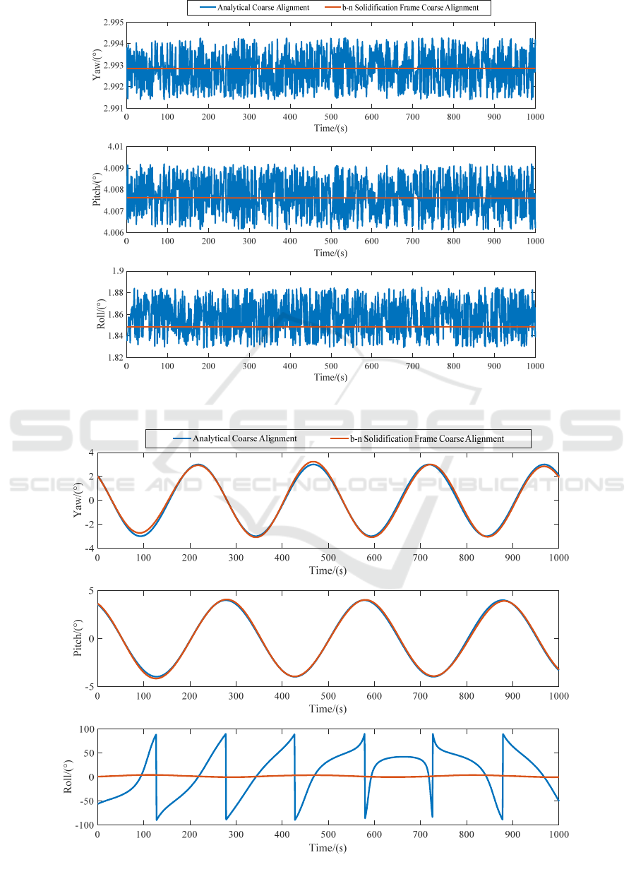
Figure 1. Static base two coarse alignment method results.
ICVMEE 2019 - 5th International Conference on Vehicle, Mechanical and Electrical Engineering
240
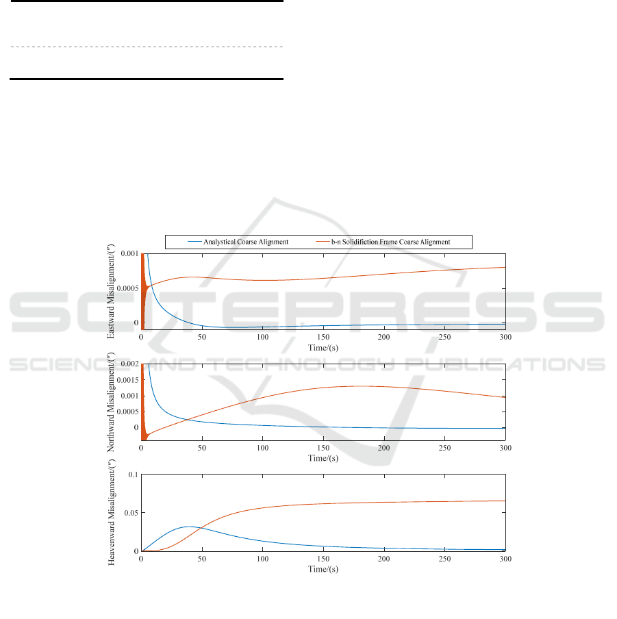
Figure 2. Angular sway base two coarse alignment method results.
The two alignment processes are completed by
introducing a fine alignment method of Kalman
filtering. The scheme is shown in Table 1.
Table 1. Two alignment schemes.
Alignment
Scheme 1
b-n Solidification Frame Coarse
Alignment (2min)
+ Kalman Filter Fine Alignment (5min)
Alignment
Scheme 2
Analytical Coarse Alignment (2min)
+ Kalman Filter Fine Alignment (5min)
The simulation results are shown in Fig.3, 4,
regardless of the static base or the angular sway
base, the b-n solidification frame and Kalman filter
method has little difference between the eastward
misalignment angle and the northward misalignment
angle with the analytical coarse alignment and
Kalman filter method, however, the two methods
have large deviations from the heavenward
misalignment angle. Under static base, the method
of analyzing coarse alignment and Kalman filter fine
alignment, the eastward misalignment angle is
0.0007″, the northward misalignment angle is
0.0009″, and the heavenward misalignment angle is
0.067″. The method of b-n solidification frame
coarse alignment and Kalman filter fine alignment,
the three misalignment angles are almost 0″.Under
the condition of angular sway base, the method of
analysing coarse alignment and the Kalman filter
fine alignment, the eastward misalignment angle is
0.017″, the northward misalignment angle is -
0.0103″, and the heavenward misalignment angle is
1.914″; The b-n solidification frame coarse
alignment and the Kalman filter fine alignment
method, the eastward misalignment angle is -
0.0039″, the northward misalignment angle is -
0.002″, and the heavenward misalignment angle is
0.1392″.
Figure 3. Static base two alignment scheme results.
New Method for Initial Alignment of Angular Sway Base based on b-n Solidification Frame
241
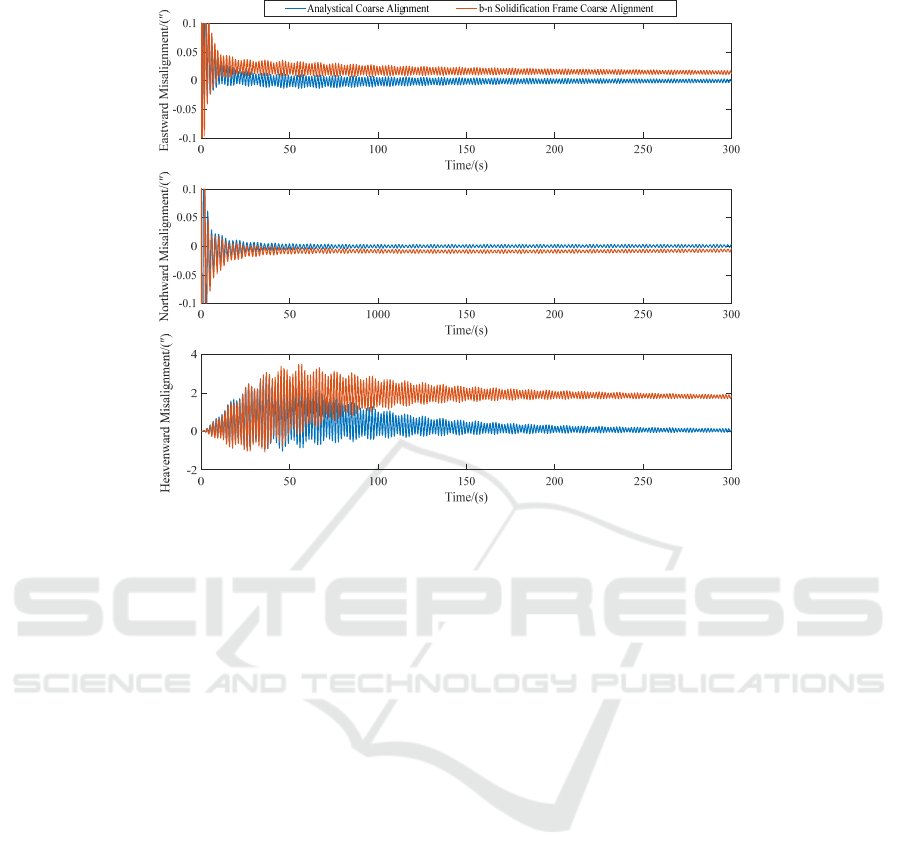
Figure 4. Angular sway base two alignment scheme results.
4 CONCLUSION
In this paper, a method of coarse alignment of
strapdown inertial navigation based on b-n
solidification frame is proposed. This method is
obtained by the method of double vector attitude
determination by the components of gravity vector
in navigation frame and body frame at different
moments. The attitude angle at the initial moment.
The method can effectively shield the interference of
the angular sway on the initial alignment, especially
the disturbance of the roll angle. Combined with the
Kalman filter fine alignment method, the simulation
results show that the method can reduce the
eastward misalignment angle by 77.1%, reduce the
northward misalignment angle by 80.9%, and reduce
the heavenward misalignment angle by 92.7%. In
general, the method has high alignment accuracy
and is highly applicable.
REFERENCES
D. H. Titterton and J. L. Weston, “Strapdown Inertial
NavigationTechnology”, 2nd ed. Stevenage:
Institution of Electrical Engineers, 2004, ch. 10.
H. Y. Zhao, H. Shang, Z. L. Wang and M. Jiang,
“Comparison of initial alignment methods for
sins”.World Congress on Intelligent Control and
Automation June 21-25 2011, Taipei, Taiwan.
J. Li, Y. Wang, Y. Li and J. Fang, “Anti-disturbance initial
alignment method based on quadratic integral for
airborne distributed pos”. IEEE Sensors Journal,
vol.18, no.11, pp.4536-4543, 2018.
K. S. Yan and Y. L. Liu, “Research on initial alignment
method of sins under shaking base”. Modern
navigation, no.4, pp.249-252, Aug. 2017.
L. B. Chang, J. S. Li and S. Y. Chen, “Initial alignment by
attitude estimation for strapdown inertial navigation
systems”. IEEE Transactions on Instrumentation and
Measurement, vol.ps-64, no.3, pp.784-794. Mar. 2015.
L. Schimelevich and R. Naor, ”New approach to coarse
alignment”,Position Location and Navigation
Symposium, Atlanta, GA, pp. 324-327, Apr. 1996.
N.S. Reddy and J. Murray, “Transfer Orbit stage
Gyrocompass Alignment Algorithm Twist and Sway
Environment for Mars Observer Mission on
Commercial Titan”, Aerospace and Electronic
Systems Magazine, vol. 6, no. 2, pp. 3-7, Feb. 1991.
O. Tekinalp and M. Ozemre, “Artificial Neural Networks
for TransferAlignment and Calibration of Inertial
navigation Systems”, AIAA, A01-37217, pp. 1-10,
2001.
Wang Xinlong. The basis of inertial navigation.
Northwestern Polytechnical University Press, Xi’an,
2013.
Y. Y. Qin, Initial Navigation. Science Press, Beijing,
2009, pp. 9.
Y. X. Wu and X. F. Pan, “Velocity/position integration
formula part I: application to in-flight coarse
ICVMEE 2019 - 5th International Conference on Vehicle, Mechanical and Electrical Engineering
242

alignment”. Aerospace & Electronic Systems IEEE
Transactions on, vol.ps-49, no.2, pp.1006-1023. Jul.
2011.
New Method for Initial Alignment of Angular Sway Base based on b-n Solidification Frame
243
