
A Method for Calculating Power Supply Capacity of a High Voltage
Distribution Network based on Power Supply Area Division
Ziao Gui
1, a
, Dongxue Sun
2, b, *
, Zhuding Wang
3
and Xianglu Pang
3
1
Northern Arizona University, State of Arizona, America
2
State Key Laboratory of Power Transmission Equipment & System Security and New Technology , Chongqing University,
Chongqing, China
3
Chongqing Star Electrical Company, Chongqing, China
Keywords: High voltage distribution network, power supply area division, typical wiring mode, voltage constraint.
Abstract: Starting from the application purpose of distribution network planning and the idea of solving a large-scale
and complex problem through using a simple method, a practical method is proposed for calculating the
power supply capacity of a high voltage distribution network based on power supply area division. Based on
relatively independent power supply subareas, the power supply capacity of a high voltage distribution
network is obtained by the direct accumulation of its subareas’ power supply capacities. As part of that
work, an approximate estimation formula is deduced, which can convert the allowable line voltage loss into
a corresponding capacity constraint, so that the influence of voltage quality on power supply capacity can be
concisely considered. Also, the approximate formulas are deduced for estimating the power supply
capacities of typical high-voltage wiring modes, which are convenient for manual calculation or
intervention. The example shows that the presented model and method are intuitive, simple, stable and
effective, and are convenient for popularization and application in practice.
1 INTRODUCTION
The total supply capability (TSC) of a distribution
network generally refers to the total load supply
capacity of that network to meet the “N−1” safety
criterion in a certain power supply area.
At present, the methods of calculating the power
supply capacity of a distribution network are mainly
divided into two categories. One is to model TSC as
a non-linear programming problem (Xiao Jun, et.al,
2014; Fan T, et.al, 2013), in which the power flow-
based power supply capacity model is generally
adopted in order to improve the calculation accuracy
with the upper and lower bounds of node voltages
being involved. However, that method is complex
and computational cost is large, and is mainly used
for the power supply capacity calculation under
actual operating condition. The other is to model
TSC as a linear programming problem (Liu Hong,
et.al, 2012; Zhai Guodong, et.al, 2018), which
simplifies the calculation model without voltage
constraints being considered, and is suitable for the
power supply capacity calculation of future planning
network with uncertainties in grid structures and
loads. However, that method results in a big
calculation error for the long lines with heavy loads
(especially in the case of load transfer at "N-1")
(Xiao Jun, et.al, 2014).
Aiming at engineering application, a simple
thinking line is adopted in this paper to solve the
calculation of power supply capacity of a large-scale
complex distribution network. The power supply
capacity of a high voltage distribution network is
calculated by accumulating the power supply
capacities of its subareas (or wiring modes). An
approximate estimation formula is deduced for
transforming the allowable voltage loss of a typical
wiring mode into a corresponding line capacity, so
that the voltage constraints can be approximately
taken into account with the computational cost being
increased slightly. Also, an approximate formula is
derived to estimate the power supply capacity of a
typical high voltage wiring mode, which is
convenient for manual calculation or intervention.
450
Gui, Z., Sun, D., Wang, Z. and Pang, X.
A Method for Calculating Power Supply Capacity of a High Voltage Distribution Network based on Power Supply Area Division.
DOI: 10.5220/0008872104500455
In Proceedings of 5th International Conference on Vehicle, Mechanical and Electrical Engineering (ICVMEE 2019), pages 450-455
ISBN: 978-989-758-412-1
Copyright
c
2020 by SCITEPRESS – Science and Technology Publications, Lda. All rights reserved

2 OVERALL THINKING LINE
Considering the relative independence of sub-areas,
a simplified calculation method is presented to
calculate the overall power supply capacity of a high
voltage distribution network.
2.1 Area Division Based Power Supply
Capacity Calculation
The power supply area division is to convert the
calculation of overall power supply capacity of a
high voltage distribution network from large to small
and from complex to simple. The principle of power
supply area division is that the power supply
subareas are relatively independent in electricity (or
power supply capacity), such as the typical high-
voltage wiring modes of radiation wiring, loop
wiring, T and π chain wiring, etc.
The calculation steps of power supply capacity
are as follows. Firstly, the power supply area
division of a high voltage distribution network is
performed to obtain relatively independent subareas
based on different wiring modes. Secondly, the
approximate estimation is made for the power
supply capacities of small-scale power supply
subareas. Finally, the total power supply capacity is
obtained by directly accumulating the power supply
capacities of those power supply subareas.
2.2 Current and Voltage Constraints
Based Allowable Line Capacity
Because there are a lot of uncertainties for network
planning, the maximum allowable voltage losses of
lines are used to approximately represent voltage
constraints instead of the upper and lower limits of
node voltages, and the maximum allowable line
voltage losses are converted the corresponding
allowable line capacities. The smaller value of the
current and voltage-based capacities for a line is
taken as the final capacity constraint of the line.
The current-based capacity for a line can be
expressed as
N, N max,
3
ll
SUI
(1)
Where
N,l
S
is the current-based allowable
capacity of line l,
N
U
and
max,l
I
are respectively the
rated line voltage and current of line l.
In this paper, the voltage-based capacity of a line
means the line’s maximum apparent power which
does not result in the violation of maximum
allowable line voltage loss. With the current and
voltage constraints being satisfied, the final line
capacity can be expressed as
C, N, V,
min ,
lll
SSS
(2)
Where
V,l
S
is the capacity corresponding to the
maximum allowable voltage loss of line l.
The voltage loss of line l can be approximately
expressed as
N
cos
1tan
ll l l
l
l
SrL x
U
Ur
(3)
Where Ll and
ll
rjx
are respectively the length
and the impedance per unit length of line l, and Sl
and
cos
are respectively the apparent power and
power factor of line l,.
Let
0
ξ
be equal to
N
cos tan /
ll
rx U
.
According to (3), the capacity corresponding to the
maximum allowable voltage loss can be expressed
as
max, N
V,
0
l
l
l
UU
S
L
(4)
Where
max, l
U
is the maximum allowable
voltage loss of line l.
3 VOLTAGE LOSS BASED
CAPACITY FORMULAS FOR
TYPICAL WIRING MODES
According to the characteristics of high voltage
lines, a simplified formula is derived to convert the
allowable voltage loss into an equivalent capacity
with the per unit length impedance being assumed to
be the same for a wiring mode.
(1) Single-Line Single-Substation
For the wiring mode of single-line single-
substation, the capacity corresponding to the
maximum allowable voltage loss can be expressed
as
max,
V,1
01
l
U
S
L
(5)
A Method for Calculating Power Supply Capacity of a High Voltage Distribution Network based on Power Supply Area Division
451
According to the relevant guidelines, the
maximum allowable voltage deviation under
abnormal conditions need to satisfy the requirement
of ±10% (Wang Li, 2015) for a high voltage
distribution network, i.e., the maximum allowable
voltage loss under ideal conditions is no more than
20%, and in addition the maximum voltage loss
under normal conditions is no more than 5%.
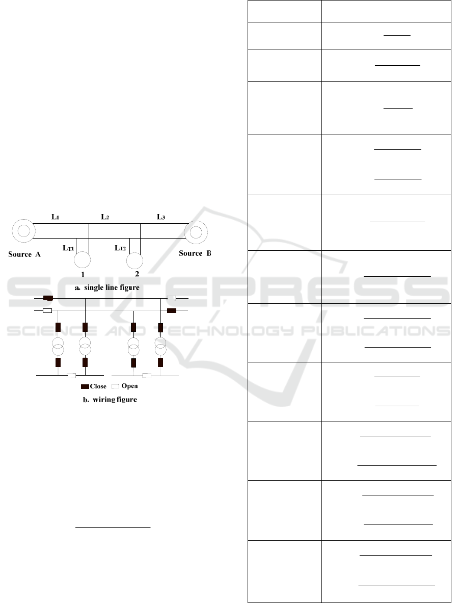
(2) Double-chain T-connected
The wiring mode of double-chain T-connected
and the normal operational states of its switches are
shown in Figure 1. By taking the outage of power
source B as an example, the formula for the voltage-
based capacity of line L1 is deduced below.
Based on (3), the maximum voltage loss for the
line of L1 and L2 can be expressed as
max, 0 T1 1 T2 1 2 T2
+
l
USLSLLL
(6)
Figure 1. Schematic diagram of double-chain and T-
connected wiring.
Where ST1 and ST2 are the maximum allowable
loads of substations 1 and 2 respectively.
Assuming that ST1 and ST2 are the same, the
maximum allowable load ST2 can be obtained
according to (6) as follows.
max,
T2
012T2
2
l
U
S
L
LL
(7)
The voltage-based capacity of line L1 can be
expressed as
Table 1. Summary of voltage -based capacity estimation
formulas for typical wiring modes.
Connection
Modes
Voltage-based Line Capacity
Estimation Formula
Single-radiation
single-substation
max,
V,1
01
l
U
S
L
Single-radiation
double-
substation
max,
V,1
012
2
(2 )
l
U
S
L
L
Double-radiation
(Or Single-
ring/chain)
Single-
substation
max,
V,1
01
l
U
S
L
Single-ring/
chain Double-
substation
max,
V,1
012
2
2
l
U
S
LL
max,
V,3
02 3
2
2
l
U
S
LL
Double-
radiation
π-
connected
Double-
substation
max,
V,1
01 2
2
2+0.5
l
U
S
LL
Double-
radiation
T-
connected
Double-
substation
max,
V,1
012T2
2
2
l
U
S
LL L
Double-chain
T-connected
Double-
substation
max,
V,1
012T2
2
2
l
U
S
LL L
max,
V,3
02 3 T1
2
2
l
U
S
LLL
Double-ring/
chain T-
connected
Double-
substation
max,
V,1
012
2
2
l
U
S
LL
max,
V,3
02 3
2
2
l
U
S
LL
Double-chain
T-connected
Triple-substation
ma x,
V,1
01 23T3
3
32+
l
U
S
LLLL
max,
V,4
02 3 4 T1
3
(23 )
l
U
S
LLLL
Triple-chain
T-connected
Double-
substation
max,
V,1
012T2
2
2
l
U
S
LLL
max,
V,3
02 3 T1
2
2
l
U
S
LLL
Triple-chain
T-connected
Triple-substation
ma x,
V,1
01 23T3
3
32+
l
U
S
LLLL
ma x,
V,4
02 3 4 T1
3
+2 3
l
U
S
LL LL
ICVMEE 2019 - 5th International Conference on Vehicle, Mechanical and Electrical Engineering
452
max,
V,1 T1 T2
012T2
2
2
l
U
SSS
LL L
(8)
Similar to the deduction of (8), if power supply
source A is out of operation, the voltage-based
capacity of line L3 can be expressed as
max,
V,3
02 3 T1
2
2
l
U
S
LLL
(9)
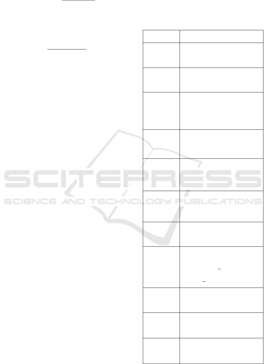
(3) Summary of Voltage-Based Capacity
Estimation Formulas for Typical Wiring Modes
Using the deduction process similar to the above,
the voltage-based capacity estimation formulas for
typical wiring modes can be obtained as shown in
Table 1.
4 POWER SUPPLY CAPACITY
CALCULATION OF A HIGH
VOLTAGE DISTRIBUTION
NETWORK
4.1 High Voltage Subareas
In this paper a high-voltage subarea is defined as the
high-voltage local network whose high-voltage lines
can support one another through the tie-switches,
such as the typical wiring modes.
(1) Single-Line Single-Substation
Based on (2), the maximum allowable load of
line L1 in the normal operation condition can be can
be expressed as
C,1 N,1 V,1
min ,SSS
(10)
Considering that the "N-1" safe power supply
capacity is 0 for the wiring mode of a single line and
a single substation, the power supply capacity in this
case is defined as the maximum allowable load in
the normal operation condition, and can be
expressed as
HTC C,1 Sub,1
min ,CSC
(11)
(2) Double-chain T-connected
In the wiring mode shown in Fig. 1, the capacity
constraint of L2 are generally neglected when
calculating the power supply capacity because the
power flowing through L2 is smaller than that
through L1 and L3. Therefore, based on (2), is the
power supply for the series circuit of double-chain
T-connected wiring mode can be approximately
expressed as
Table 2. Summary of power supply capability estimation
formulas for typical high voltage wiring modes.
Connection
Modes
Power Supply Capacity
HTC
C
Single-
radiation
single-
substation
C,1 Sub,1
min ,SC
Single-
radiation
double-
substation
C,1 Sub,1 C,2 Sub,2
min , min ,SC SC
Double-
radiation (Or
Single-
ring/chain)
Single-
substation
C,1 Sub,1
min ,SC
Single-ring/
chain
Double-
substation
C,1 C,3
Sub,1 C,2 Sub,2
Sub,2 C,2 Sub,1
min , ,
+min , ,
+min ,
SS
CSC
CSC
Double-
radiation π-
connected
Double-
substation
C,1 Sub,1
hvm C,2 Sub,2
min{ ,
2, }
SC
fSC
Double-
radiation
T-
connected
Double-
substation
C,1 C,T1 Sub,1
C,T 2 Sub,2
min{ , min ,
min , }
SSC
SC
Double-chain
T-connected
Double-
substation
C,1 C,3 C,T1 Sub,1
C,T 2 Sub, 2
mi n { , , mi n ,
min , }
SS S C
SC
Double-ring/
chain T-
connected
Double-
substation
HTC1 C 1 Sub 1
Sub 2 C 3 Sub 2 Sub 1
C,1 C,3 Sub,1 Sub,2
Sub,1 Sub,2
min{min , +
,min + ,
1
min[ , , ]
2
1
}
2
CSC
CSCC
SS C C
CC
,,
,,,,
,
Double-chain
T-connected
Triple-
substation
C,1 C,4 C,T1 Sub,1
C,T2 Sub,2 C,T3 Sub,3
min{ , ,min ,
min , min , }
SS S C
SC SC
Triple-chain
T-connected
Double-
substation
C,1 C,3 hvm C,T1 Sub ,1
hvm C,T2 Sub,2
min{2 ,2 , 2 ,
2 , }
SSf SC
fSC
Triple-chain
T-connected
Triple-
substation
C,1 C,4 hvm C,T1 Sub,1
hvm C,T2 Sub,2 hvm C,T3 Sub,3
min{2 , 2 , 2 ,
2, 2, }
SSf SC
fSC fSC
A Method for Calculating Power Supply Capacity of a High Voltage Distribution Network based on Power Supply Area Division
453
CL V 1 N ,1 V 3 N,3
min , , ,SSSSS
,,
(12)
The power supply capacity for the T-connected
circuit of double-chain T-connected wiring mode
can be expressed as
CT C,T1 sub,1 C,T2 sub,2
min , min ,SSS SS
(13)
The overall power supply capability can be
expressed as
HTC CL CT
min ,CSS
(14)
(3) Summary of Power Supply Capacity
Estimation Formulas for Typical Wiring Modes
By using the derivation process similar to the
above, the power supply capacities of typical wiring
modes can be obtained as shown in Table 2.
4.2 High Voltage Distribution Network
Based on the subareas of typical wiring modes, the
overall power supply capacity calculation of a high-
voltage distribution network can be expressed as
HTC
HV HTC,
1
N
i
i
CC
(15)
Where CHVC,i is the power supply capacity of
subarea i and NHTC is the number of subareas.
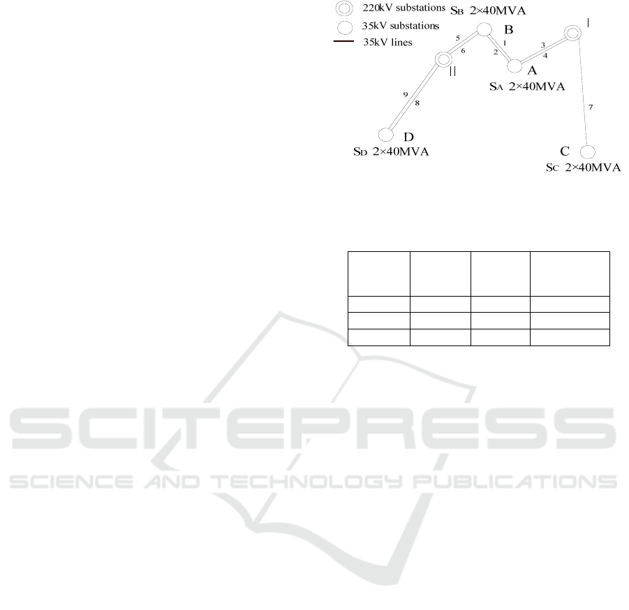
5 EXAMPLE
(1) System Introduction
As shown in Fig. 2, the high-voltage distribution
network includes three kinds of typical wiring
modes, i.e., double-chain π-connected of substations
A and B, single-line and single-substation of
substation C and single-substation double-line of
substation D. The conductor types of each 35kV
high voltage lines are LGJ-400, and their current-
based capacities are 51.23MVA, and their lengths
are shown in Table 3. The known power supply
capacities of substations A, B, C and D are 47.29
MVA, 52.42 MVA, 17.68 MVA and 40 MVA,
respectively.
Figure 2. Schematic diagram of the high-voltage
distribution network.
Table 3. HV line parameters.
Line
Name
Line
Length
(km)
Line
Name
Line Length
(km)
1,2 6.3 7 24.8
3,4 9.2 8,9 35.2
5,6 7.5 / /
(2) Power Supply Capacity of Subareas
According to Table 2, the power supply capacity
of double-chain π-connected wiring mode is 98.52
MVA. The power supply capacity of single-line
single-substation wiring mode is 11.12 MVA. The
power supply capacity of single-substation double-
line is 15.65 MVA.
Without considering voltage constraints, the
power supply capacity of single-line single-
substation is 32 MVA and that of single-substation
double-line is 40 MVA.
(3) Overall Power Supply Capacity
According to (15), the overall power supply
capacity is 125.29 MVA. Without considering
voltage constraints, the power supply capacity is
170.52 MVA, which is 36.1% higher than that of
125.29 MVA with voltage constraints being
considered.
6 CONCLUSIONS
The main conclusions are as follows:
(1) Based on the relatively independent power
supply subareas (or wiring modes), a simplified
method is proposed for calculating the power supply
capacity of a high-voltage distribution network.
(2) The upper and lower limit constraints of node
voltages are skillfully converted to the maximum
allowable line voltage loss ones which are then
transformed into line capacity ones. Thus, voltage
ICVMEE 2019 - 5th International Conference on Vehicle, Mechanical and Electrical Engineering
454

constraints can be automatically considered when
the capacity constraints are taken into account,
which simplifies the calculation process and solves
the calculation error problem caused by neglecting
voltage constraints.
(3)The approximate formulas are derived for
estimating the power supply capacities of typical
high-voltage wiring modes. These formulas are of
practical value in engineering application.
(4) The proposed model and method are more
realistic, intuitive, simple, fast, stable and effective,
and easy to be popularized and applied in practice.
As long as the basic idea and method in this paper
are mastered, planners can use simple computing
tools or even rely on manual work to complete
specific tasks.
REFERENCES
Xiao Jun, Liu Shisong, Li Zhensheng, et al. 2014. 34 (31):
5516-5524, Distribution network maximum power
supply capacity model based on power flow
calculation. Chinese Journal of Electrical Engineering.
Fan T, Chen X, Liao Y, et al. 2013. IEEE Region 10
Conference (31194), the maximum power supply
capability calculation based on the actual load
characteristics. IEEE.
Liu Hong, Guo Yuchang, Ge Shaoyun, et al. 2012. 36(3):
217-222, Correction Calculation Method for Power
Supply Capacity of Distribution System. Power
System Technology.
.Zhai Guodong, Gao Xinzhi, Yu Shugang, et al. 2018
42(10): 3420-3432, Practical Model of Residual Power
Supply Capacity of Distribution Network. Power
System Technology.
Xiao Jun, Li Zhensheng, Liu Shisong, et al. 2014. 38 (05):
36-43, the influence of voltage constraints and
network losses on the calculation of large power
supply capacity of distribution networks. Power
System Automation.
Agricultural and Electrical Work Department of State Grid
Corporation, 2006. Training Textbook for Rural
Power Grid Planning. China Power Publishing House.
A Method for Calculating Power Supply Capacity of a High Voltage Distribution Network based on Power Supply Area Division
455
