
Research on Unmanned Vehicle Path Planning based on Improved
Artificial Potential Field Method
Guiling Ju
1, a, *
, Weihai Sun
2
, Hongjuan Hu
1
and Yuanyuan Wu
3
1
Mathematics of Department of Basic Courses, Academy of Army Armored Forces, Beijing, China
2
Vehicle Engineering Department, Academy of Army Armored Forces, Beijing, China
3
English of Department of Basic Courses, Academy of Army Armored Forces, Beijing, China
Keywords: Path planning, artificial potential, unmanned vehicle, simulation experiments.
Abstract: Path planning is one of the most important tasks in unmanned vehicle navigation system. Artificial potential
field method has been widely used in real-time obstacle avoidance trajectory control due to its advantages of
simple structure, less computation and strong robustness. However, it also has the problems of local
minimum point and unreachable target. Aiming at this defect of artificial potential field method in
unmanned vehicle path planning, the gravitational potential field function and repulsive potential field
function were improved, and the effectiveness of the algorithm is verified by simulation experiments.
1 INTRODUCTION
Unmanned vehicle is of great significance in
alleviating road congestion, reducing traffic
accidents and reducing driver fatigue. In the
unmanned vehicle system, path planning is the basis
of intelligent vehicle navigation and control. For the
problem of path planning, many algorithms are
proposed, such as genetic algorithm, ant colony
algorithm, particle swarm optimization, neural
network algorithm and so on. These algorithms play
a positive role in the research of path planning, but
they also have arithmetic. The method is complex
and computationally expensive, and it is inefficient
for path planning (H. Liu, J. Mao 2013; L.Yin, Y. X.
Yin, 2009; D. Q. Shi, E. G. Collins, D. Dunlap,
2008). The artificial potential field method has the
advantages of simple structure, small calculation and
easy control. Therefore, it has been widely used in
real-time obstacle avoidance. However, the
traditional artificial potential field method has the
following shortcomings: 1) no path can be found
between two obstacles close to each other; 2) there is
oscillation problem in front of obstacles; 3) When
there are obstacles near the target point, it can not
reach the target point; 4) there is a local minimum
(C. L. Liu, 2012; J. Y. Zhang, T. Liu, 2007; X. X.
Liang, et.al, 2018; J. Y. Zhang, et.al, 2006).
Aiming at the problem of target unreachability
and local minimum point in the path planning of
unmanned vehicle, this paper studies it.
2 ARTIFICIAL POTENTIAL
FIELD METHOD
Artificial potential field method (C. L. Liu, 2012)
was proposed by Khatib in 1986. The basic idea is to
regard the motion of the unmanned vehicle as a kind
of motion in the virtual artificial force field. The
target point produces gravitation to the unmanned
vehicle, while the obstacle produces repulsion to the
unmanned vehicle. The unmanned vehicle avoids the
obstacle and moves to the target point under the
combined force of gravitation and repulsion.
Note as gravitational potential field
function, the traditional function of it is usually
taken as follows
2
1
() (, )
2
att g
Ux xx
(1)
In the formula, represents the gravitational
potential field coefficient, represents the current
position of the unmanned vehicle, represents the
()
att
Ux
x
g
x
Ju, G., Sun, W., Hu, H. and Wu, Y.
Research on Unmanned Vehicle Path Planning based on Improved Artificial Potential Field Method.
DOI: 10.5220/0008869204310434
In Proceedings of 5th International Conference on Vehicle, Mechanical and Electrical Engineering (ICVMEE 2019), pages 431-434
ISBN: 978-989-758-412-1
Copyright
c
2020 by SCITEPRESS – Science and Technology Publications, Lda. All rights reserved
431

position of the target point, and represents
the distance between the position of the unmanned
vehicle and the position of the target point. From
this function, it can be seen that the larger the
distance between the unmanned vehicle and the
target point, the stronger the gravitational potential
field function and the greater the gravitation.
Note as repulsive potential field
function, the traditional function of it is usually
taken as follows:
2
0
0
0
111
,(,)
()
2(,)
0, ( , )
o
rep
o
o
xx
Ux
xx
xx
(2)
In the formula, represents the repulsive
potential field coefficient, represents the
distance between the current position of the
unmanned vehicle and the position of the obstacle,
and represents the repulsive force acting
distance of the obstacle. From this function, the
smaller the distance between the unmanned vehicle
and the obstacle, the stronger the repulsive potential
field and the greater the repulsion.
Note as the potential field of the position
which the unmanned vehicle locates, it is taken as
follows
() () ()
att rep
Ux U x U x
Note
(), (), ()
att rep
F
xF xFx
as gravitation,
repulsion and resultant force of the unmanned
vehicle respectively.
() () () () ()
att rep att rep
F
xFxFx Ux Ux
The unmanned vehicle moves to the target point
under the resultant force.
3 IMPROVEMENT OF
ARTIFICIAL POTENTIAL
FIELD METHOD
Aiming at the problems of the artificial potential
field method in the path planning of unmanned
vehicle, the algorithm is improved.
3.1 Target Unreachable Problem and
Solution
If there are obstacles near the target point, the
unmanned vehicle moves closer to the target point
and closer to the obstacle at the same time.
According to the definition of the gravitational
potential field and the repulsive potential field
function mentioned above, in the process of moving
to the target point, the gravitation will be smaller
and smaller, while the repulsion will be larger and
larger. When the repulsion is greater than the
gravitation, the unmanned vehicle will not continue
to move towards the target point, which will lead to
the problem of not reaching the target point.
Therefore, the repulsive potential field function is
improved by introducing the power of distance
factor between unmanned vehicle and target point.
2
2
0
0
0
(, )
11
,(,)
()
2(,)
0, ( , )
g
o
rep
o
o
xx
xx
Ux
xx
xx
(3)
Formula (3) shows that the repulsion will be
greatly reduced when the unmanned vehicle moves
towards the target point, and the repulsive potential
field will be the smallest at the target point. Thus, it
is ensured that he local minimum point only toccurs
at point
g
x
and the unreachable problem can be
avoided.
3.2 Local Minimum Point Problem and
Solutions
In the process of driving, when the gravitation and
repulsion of the unmanned vehicle are the same and
the direction is opposite, the resultant force of the
unmanned vehicle is 0, and the unmanned vehicle
cannot continue to move forward, thus causing the
local minimum point problem.
In order to avoid this problem, when the
unmanned vehicle enters the local minimum point,
the direction of gravitational potential field can be
changed artificially, so that the force at the point
becomes unbalanced, so as to help the unmanned
vehicle find the next moving point.
The gravitational potential field function is
modified as follows
2
cos sin
1
() (, )
sin cos
2
att g
Ux xx
(4)
(, )
g
x
x
()
rep
Ux
(, )
o
x
x
0
()Ux
ICVMEE 2019 - 5th International Conference on Vehicle, Mechanical and Electrical Engineering
432
In the formula (4), the variable
represents the
angle of the change of the gravitational potential
field direction.
Because of the random angle
, the direction of
the oscillating potential field can be selected
randomly to ensure the operation of the oscillating
potential field, so that the unmanned vehicle can
jump out of the current point, and then the path
planning is carried out according to the artificial
potential field method function (1). If the unmanned
vehicle falls into the local minimum state again, the
gravitational potential field function is switched
from function (1) to (4). Then it goes down in turn
until the unmanned vehicle avoids all the local
minimum points in the driving process and reaches
the target point.
4 SIMULATION VERIFICATION
In order to verify the effectiveness of the improved
artificial potential field method, the simulation
experiment is carried out through software
MATLAB. For the convenience of discussion, the
size and shape of unmanned vehicles and obstacles
are treated as a particle.
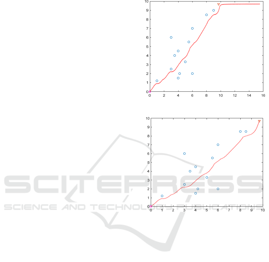
In the simulation, the starting point is (0, 0), (9.7,
9.7) is the target point. Obstacles are represented by
small circles, target points are represented by
triangles, the gain coefficients of gravitation and
repulsion are 5 and 1 respectively, and the deviation
angle is 30 degrees. The results of path planning are
shown in the figure.
Aiming at the obstacles near the target point and
the repulsion is greater than gravitation, the path
planning curves of the traditional artificial potential
field method and the improved artificial potential
field method are given in Fig.1 and Fig.2
respectively. The simulation results show that the
improved artificial potential field method can
effectively avoid the problem that the unmanned
vehicle cannot reach the target point.
Figure 1. Traditional artificial potential field method.
Figure 2. Improvement of artificial potential field method.
Aiming at the problem of local minimum, the
path planning curves of traditional artificial potential
field method and improved artificial potential field
method are given in Fig.3 and Fig.4. The simulation
results show that the improved artificial potential
field method can effectively avoid the problem of
local minimum.
Research on Unmanned Vehicle Path Planning based on Improved Artificial Potential Field Method
433
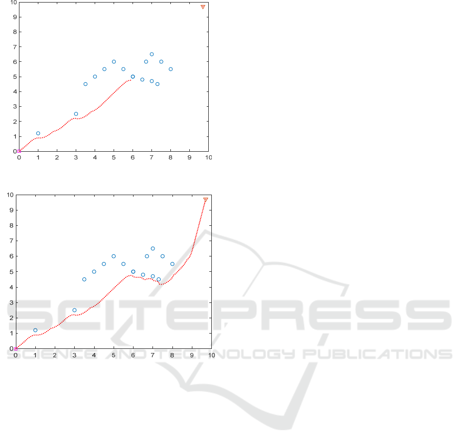
Figure 3. Traditional artificial potential field method.
Figure 4. Improvement of artificial potential field method.
5 CONCLUSION
The artificial potential field method may cause local
minimum and unreachable problems in path
planning. To solve this problem, the gravitational
potential field function and repulsive potential field
function are improved. The feasibility of this method
is verified by simulation. However, it does not
consider whether the planned path is the optimal
path and whether the planned path is smooth, etc.
These problems need further study.
ACKNOWLEDGMENTS
This work was financially supported by the college's
self-initiated fund project 2018CJ31.
REFERENCES
C. L. Liu, Research on robot path planning technology
based on potential field method and genetic
algorithms, Nanjjing. Uni.Tech.,Nanjing, 2012, pp.
651–654.
D. Q. Shi, E. G. Collins, D. Dunlap, Robot navigation in
cluttered 3-D environments using preference-based
fuzzy behaviors, Sys, Man and Cybernetics, Commun.
7(2008)1486-1499.
H. Liu, J. Mao, Walking stability simulation of excavators
under complex road conditions, J. Liaoning. Tech.
Uni., Commun. 32 (2013) 377-380.
J. Y. Zhang, T. Liu, Optimal path planning for mobile
robots based on artificial potential field method, J.
Aeronautics, Commun. 28(2007) 183-188.
J. Y. Zhang,Z. P. Zhao, T. Liu, Robot path planning based
on artificial potential field method, J. Harbin
University of Technology, Commun. 38(2006) 1306-
1309.
L.Yin, Y. X. Yin, Path planning simulation based on
dynamic artificial potential field method, J.
Sys.Simulation, Commun. 21(2009) 3325-3341.
X. X. Liang, C. Y. Liu, X. L. Song, Y. K. Zhang, Path
planning of mobile robot based on improved artificial
potential field method, Computer simulation,
Commun. 35(2018) 291-295.
ICVMEE 2019 - 5th International Conference on Vehicle, Mechanical and Electrical Engineering
434
