
Research on Over-Temperature using of PEM Evaluation Method in
Military
Xuliang Wang
1
, Yuan Liang
2, a
1
93128 PLA TROOPS, 14#, Fuxing road, Haidian district, Beijing, China
2
Equipment Department, China Aero-Polytechnology Establishment, Jingmi Road 7#, Chaoyang district, Beijing, China
Keywords: PEM, over-temperature, reliability.
Abstract: In order to evaluate the reliability of over-temperature using of Plastic Encapsulated Microcircuit (PEM) in
military, this paper designs tests to simulate environmental suitability and lifetime by analyzing the failure
mode and mechanism of PEM (the plastic encapsulated microcircuit). Based on the analysis, the evaluating
tests are designed and conducted, and the result shows that HAST (High accelerated stress temperature),
temperature cycling, and Steady state life test under the operating condition but within the maximum
temperature limit, can be chosen to evaluate the reliability of the devices used over-temperature in sequence.
This provides a set of feasible evaluation methods for the over-temperature using of PEM, which can
effectively guarantee the quality and reliability of PEM, also provides theoretical basis for the subsequent
formation of effective evaluation methods and standards for the screening and detection of the over-
temperature using of PEM.
1 INTRODUCTION
Plastic package is the main form of electronic
components packaging, for its low cost, small size as
well as light weight, etc. It is a statistical fact that
92% of IC components and discrete devices use the
plastic package at present.
As the moisture absorption and the mismatch of
thermal expansion coefficient of epoxy resin, the
plastic encapsulated microcircuit (PEM) is generally
limited to apply in the field of aerospace, military
and high reliability industry. One of the most serious
problems is its narrower temperature range.
Comparing with the glass and ceramic,
encapsulation materials belong to low temperature,
and its vitrification transition temperature is between
130~160°C, it mainly satisfies the requirement of
the temperature range of the 3 followings: 0°C
~70°C (commercial), -40°C ~85°C (industrial) and -
40°C ~125°C (car), all the 3 temperature ranges are
narrower than military temperature range (-55°C
~125°C). Besides, there are many other application
environments that are even more extreme, such as
cold climate of avionics and spacecraft requires -
65°C or less, and the ignition control is up to 175°C,
even the aviation electronic distribution control
system reaches 225°C. If the PEM is directly used in
target temperature conditions without evaluation and
assessment, it usually causes problems such as high
failure efficiency and low reliability of electronic
products (LIANG Yuan, et.al, 2015). Therefore, it is
urgent to establish an evaluation method and
procedure for the over-temperature using of PEM to
ensure the quality and reliability, which can provide
theoretical basis for the subsequent formation of
effective evaluation methods and standards for the
screening and detection PEM in over-temperature
using.
2 FAILURE MODE AND
MECHANISM ANALYSIS OF
OVER-TEMPERATURE USING
OF PEM
Recently, the PEM reliability has greatly improved
along with the progress of the packaging materials
and coating process, while the reliability
requirement is much higher, but the main failure
mode for PEM is still delamination, especially
serious for the plastic power device with hermetic
408
Wang, X. and Liang, Y.
Research on Over-Temperature using of PEM Evaluation Method in Military.
DOI: 10.5220/0008868204080412
In Proceedings of 5th International Conference on Vehicle, Mechanical and Electrical Engineering (ICVMEE 2019), pages 408-412
ISBN: 978-989-758-412-1
Copyright
c
2020 by SCITEPRESS – Science and Technology Publications, Lda. All rights reserved

problem in the condition of high temperature with
high voltage and large current. In the process of
reliability testing and servicing, it is common to find
delamination between epoxy molding compound
(EMC) and the lead frame, as well as the micro-chip
and substrate, which leads to a series of failure
modes, such as plastic strain crack, passivation layer
damaged, leakage current increased, PN junction
damaged, etc (AndrewA.O.Tay, 1996).
Normally, there is boundary layer (transition
layer) between the copper substrate and epoxy
molding compound (EMC) in PEM. The transition
layer, different with other part of epoxy molding
compound, is the weakest position of all adhesive
interface, and makes the delamination occurring and
spreading under the stress of thermal and humidity.
If the delamination occurs between EMC and chip, it
will cause an increase in the bonding wire resistance
as well as leakage current and decrease in
breakdown voltage even turn to open-circuit due to
mechanical tensile damage, also the passivating
layer are destroyed, which provides an easier
channel for the moisture immersing into the chip
surface and lead to the metal layer corrosion; While
if the delamination occurs between EMC and copper
substrate or lead frame, it will lead to Popcorn
Effect, while provides an channel for the moisture
immersing. In conclusion, once the delamination
occurs between EMC and other material, even if the
area is small, it will become the source of
delamination, and gradually expand in the actual
usage by thermal stress or mechanical stress until it
fails (PoPeom, 1995; Sheng Nian, 2014). The table
below shows the failure analysis of PEM in main
operating stress.
Table 1. The analysis of PEM in main operating stress.
No. Failure Mode
Failure
Mechanism
1
Die crack,
die adhesive failure
Temperature
stress
2
leakage current increased,
PN junction damaged
Thermal-
electric stress
3
Migration intermetallic
compound, Ohmic contact
degradation
Thermal
stress
4 Delamination
Humid-
thermo stress
3 RELIABILITY EVALUATION
OF OVER-TEMPERATURE
USING OF PEM
3.1 Select the Test Methods
Based on the analysis above, as well as combining
with GJB 7400-2011 “General specification for
semiconductor integrated circuits of qualitied
manufacturer certification” (G. Eason, et.al, 1955),
which is used to qualify the PEM used in military,
the high temperature storage, HAST, Temperature
cycle, and Steady state life test which are chosen to
qualify the reliability of PEM. Besides, the external
visual inspection, electrical performance test in room
temperature and Scanning Acoustic Microscope
(SAM) test are conducted after each test.
Meanwhile, in order to verify whether the different
temperature have different impact in structure and
performance for PEM, comparative tests are also
carried out.
3.2 Select the Test PEMs
This paper selects PEM ADV7123KSTZ140 as the
test sample. The maximum operating temperature
specified in the device manual is 85°C, but it is
tested the maximum operating temperature in actual
use is 115°C.
In order to verify whether the device at 85°C and
115°C temperature stress have the different impacts
on the performance and structure, 20 fully qualified
devices are selected to test under the manual
regulation temperature stress 85°C, marked as 1-1;
20 fully qualified devices are selected to test under
the actual temperature stress 115°C, marked as 2-1;
20 fully qualified devices with delamination
(without pins) at the lead frame are selected to test
under the manual regulation temperature stress
85°C, marked as 1-2; 20 fully qualified devices with
delamination (without pins) at the lead frame are
selected to test under the actual temperature stress
115°C, marked as 2-2. The devices information and
the test method are shown in table 2.
3.3 Process of the Tests
3.3.1 High Temperature Storage
After the high-temperature storage test for 48hours,
it is found that the functional performance
parameters of these 4 groups do not change too
much, and the delamination area of the 1-2 and 2-2
Research on Over-Temperature using of PEM Evaluation Method in Military
409
groups do not expand obviously, while there is no
obvious change of the 1-1 and 2-1 groups, which
indicates that different high-temperature storage had
little impact on the PEMs, and the typical test results
are shown in figure 1.
Table 2. The devices information and the test method.
No. Items
Test
condition of
1-1, 1-2
Test condition
of 2-1, 2-2
1
High
temperature
storage
85,48h 115,48h
2 HAST
85%RH/85,
1000h
85%RH/115,
1000h
3
Temperature
cycle
-40~85,
500 times
-40~115,
500 times
4
Steady state
life test
1000h, 85 1000h, 115
Devices information
No.
External
visual
inspection
Electronic
performance
SAM
1-1
2-1
qualified qualified qualified
1-2
2-2
qualified qualified
Defective but
not rejected
(a) Qualified (b) Defective but not rejected
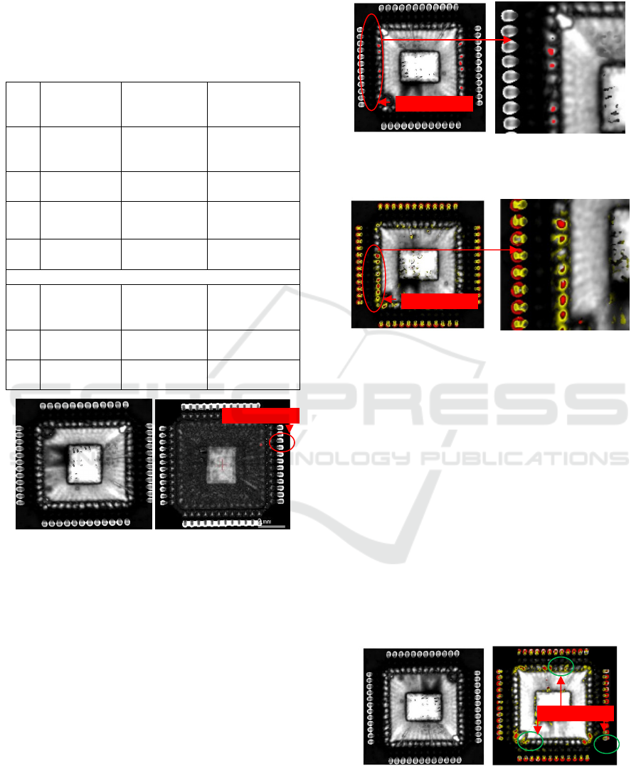
Figure 1. SAM after high-temperature storage.
3.3.2 High Accelerated Stress Temperature
The second test is High accelerated stress
temperature (HAST), it is found that the functional
performance parameters of these 4 groups do not
change too much, still qualified. Group 1-1 and
group 2-1 have no obvious defects such as cavities
and cracks arise. Meanwhile the delamination area
of groups 1-2 and 2-2 increased, but groups 1-2 was
slightly less than that of groups 2-2. It can be
inferred that HAST can makes the delamination area
expansion. However, the expansion is related to
temperature: with the same humidity, the higher the
temperature, the larger the delamination area, while
the lower the temperature, the smaller the
delamination area (Xiao haihong, 2009), and the
typical test results are shown in figure 2 and figure
3.
(a) Global photo of SAM (b) partial enlarged detail
Figure 2. SAM of group 1-2 after HAST.
(a) Global photo of SAM (b) partial enlarged detail
Figure 3. SAM of group 2-2 after HAST.
3.3.3 Temperature Cycle
The third test is temperature cycle. It is found that
the functional performance parameters of these 4
groups were still qualified, like it after HAST.
Group 1-1 and group 2-1 have no obvious defects
such as cavities and cracks arise. Meanwhile the
delamination area of groups 1-2 and 2-2 increased
than the area after HAST, and the functional
performance of these 2 groups are abnormal, and the
typical inspection results are shown in figure 4. That
is because the temperature change rate of
temperature cycle is large, and the rapid temperature
gradient will make the thermal stress increase which
makes the failure rate increase.
(a) Group 1-1, 2-1 (b) group 2-1, 2-2
Figure 4. SAM after temperature cycles.
Delamination part
Delamination part
Delamination part
Delamination part
ICVMEE 2019 - 5th International Conference on Vehicle, Mechanical and Electrical Engineering
410
Though the SEM examination for the group1-2
and group 2-2 which have the abnormal functional
performance, it is found that as the bonding line is
embedded in the packaging material and passes
through the bonding layer, the stress on the bonding
line will increase rapidly when the bonding layer
fails. The mismatch of thermal expansion coefficient
will result in repeated stress on the bonding line at
the interface with fatigue fracture. In the early stage,
crack initiate at stress point due to the repeated
action, and the stratification distance becomes
larger, the contact area becomes smaller or even
disconnects, resulting in parameter deviation or open
circuit at the low temperature. After the temperature
return to room temperature, the size of the
delamination decreases, the contact at the crack of
the bonding line resumes the connection, and the
electrical properties and functions return to normal.
If the bonding line crosses the delaminated interface,
it will cause fatigue fracture of the bonding line
under the action of thermal stress, which will
obviously increase the area of the disposed layer of
the lead frame with abnormal function and
performance of the PEMs (Driel, W.D.V, 2005).
Typical detection results are shown in figure 5.
(a) Global photo of SEM (b) partial enlarged detail
Figure 5. SEM of group 2-1 and 2-2 after Temperature
cycle.
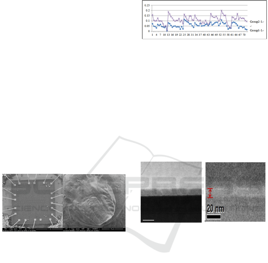
3.3.4 Steady-State Life
The remaining two groups (groups 1-1 and 2-1)
were tested at 1000h, 85h and 1000h and 110
steady-state life. It is found that the group 1-1 is
functionally qualified at 1000h and 85°C, also
without any delamination inner the devices; but the
leakage current degradation of 2-1 was significantly
greater than that of the group 1-1, as shown in figure
6.
Figure 6. Typical inspection results of leakage current.
Though the SEM examination for the group 1-1
and group 2-1, It is found that the gate oxide
thickness of group 2-1 is about 5nm, much less than
the gate oxide thickness of group 2-1, about 10nm,
that is because the lattice under high temperature is
unstable and the interface state of oxide layer
increases, resulting in the reduction of the thickness
of the gate oxide layer. through the thick oxide
breakdown voltage is (1.4~3)×107V/cm, eigen
breakdown voltage of oxide layer is (8~10)×106
V/cm. In general, under the action of electric
pressure, thin gate oxide layer is more likely to
cause breakdown, accompanied by thermal carrier
effect (TEVEROVSKY A, 2003). Typical inspection
results are shown in figure 7.
(a) Global photo of SEM (b) partial enlarged detail
Figure 7. Thickness of group 2-1 and 2-2 after Steady-
state life test.
3.3.5 Comparative Tests
The comparative tests are conducted in order to
verify whether the different temperature have
different impact in structure and performance for
PEM. We choose 5 devices from the group 2-1 after
steady-state life, and 5 new and qualified devices as
the comparative ones. According to GJB 4027A-
2006, method 1100, the external inspection, X-ray
inspection, SAM, internal inspection and SEM are
carried on by sequence, it is found that there is no
obvious difference between these 2 groups, which
means the tests for group 2-1 do not cause other
potential damage to the devices.
10 nm
10 nm
Si substrate
AlAs
GaAs
Research on Over-Temperature using of PEM Evaluation Method in Military
411

4 CLOUSION
For PEM with inherent defects, they have poor
environmental adaptability, are more easily to fail
and have lower reliability in usage under
overtemperature conditions. This is because the
mismatch of thermal expansion coefficient can cause
stress at the interface between chip and package. The
temperature gradient caused by rapid temperature
change will increase the stress and accelerate the
failure rate. If the bonding line crosses the layered
interface, it will cause fatigue fracture of the
bonding line and abnormal function and
performance of the device under the action of a wide
range of temperature stress. It can be seen from the
results of tests in this paper, that HAST, temperature
cycle, and steady life test in actual usage
temperature can lead to device failure, inherent
defects effectively eliminate and encapsulation
device used in over temperature potential failure
under the application, evaluation device
environment adaptability; However, under the
condition of high-temperature storage, the device
can only bear high-temperature stress, and the
absence of a temperature gradient prevents the
device from potentially failing. And the temperature
cycle, HAST and steady life test in actual
temperature do not cause other potential damage to
the devices.
The research results in this paper can effectively
ensure the quality and reliability of devices over-
temperature using, and provide a theoretical basis
for the detection, evaluation, screening and failure
analysis for the PEMs used in over temperature.
REFERENCES
AndrewA.O.Tay. “Moisture diffusion and Heat Transferin
Plastie IC Packages”.IEEE Transaetions on
Components Packaging and Manufaeturing
Teehnology, 1996, 19 (2), pp. 186-193.
Driel, W.D.V., Gils, M.A.J., Zhang, G.Q., Prediction of
delamination in micro-electronic packages [J].
Electronic Packaging Technology Conference. 2005:
676-681.
GJB 7400-2011“General specification for semiconductor
integrated circuits of qualitied manufacturer
certification.G. Eason, B. Noble, and I. N. Sneddon,
“On certain integrals of Lipschitz-Hankel type
involving products of Bessel functions,” Phil. Trans.
Roy. Soc. London, vol. A247, pp. 529–551, April
1955. (References)
LIANG Yuan, CIAI Liangxu, LU Xiaoqing, LU Haotian,
“The Analysis of Delamination Failure Mechanism
between Copper Substrate and EMC in Plastic
Encapsulated Microcircuit,” 7th Asia-Pacific
International Symposium on Aerospace Technology,
2015, pp.134-139.
PoPeom. “A Failure Mechanism in Plastie-
EncaPsulatedMicroeircuits” [J]. IEEE Transactionson
Reliability, 1995, 44(3), pp 362~367.
Sheng Nian. Military encapsulation device failure
mechanism research and test process [J]. Electronic
components and reliability.2014.4.pp.6~10.
TEVEROVSKY A. Instructions for Plastic Encapsulated
Microcircuit (PEM) Selection, Screening, and
Qualification [R]. NASA/TP-2003-212244:9.
Xiao haihong,. “The Research of Discrete Device of
Delamination [D]. University of Electronic Science
andTechnology of China .2009.
ICVMEE 2019 - 5th International Conference on Vehicle, Mechanical and Electrical Engineering
412
