
Detection System Design of the Glenohumeral Joint Motion
Information
Jianfeng Li
1, a
, Chunzhao Zhang
1, b
and Qiang Cao
1, c
1
College of Mechanical Engineering and Applied ElectronicsTechnology, Beijing University of Technology, No.100
Pingleyuan, Beijing, China
Keywords: Detection system, Detection mechanism, Measurement system, Glenohumeral joint motion information.
Abstract: Due to the complex coupled motion of shoulder mechanism, design the guiding movement rule of
rehabilitation robot generally lack of the glenohumeral (GH) joint motion information. This study focused
on development detection system design of the GH joint motion information. In this paper, the detection
system incorporates the detection mechanism and measurement system. Design of the detection mechanism
includes model of the shoulder complex, configuration as well as structure design of the detection
mechanism. Design of the measurement system includes hardware selection and software development.
Straight after, detection system was integrated. Then, test and analysis was presented. The results show the
detection system can measure and present the GH joint motion information in real time. It provides a
method to obtain the movement information of the GH joint, and has practical significance for shoulder
function simulation and ergonomics.
1 INTRODUCTION
With the aggravation of aging and traffic accidents
happen frequently, more and more patients with
upper limb motor dysfunction. To repair upper limb
injury, rehabilitation training equipment is more and
more popular. Due to most of the joints movements
of the upper limb need to be based on the
glenohumeral (GH) joint motion, obtainment the GH
joint motion information is very important to design
the structure of upper limb rehabilitation training
equipment and is of practical significance to ensure
the rehabilitation training effect of the affected limb
(Kirsch, 2001; Kiguchi, 2011).
The GH joint is one of the joints in the shoulder
complex and the shoulder complex is an especial
complicated and correlative system ( Tobias, 2009),
which results in extremely complex GH joint
movement. Although many researchers have studied
the coupled motion of the shoulder complex, only a
small amount of quantitative information on the GH
joint is available in the existing literature (Yang,
2005). Thus, to find a method to quantize the daily
movement information of the GH joint is necessary.
In this paper, the motion information detection
system of the GH joint is developed, which provides
a method to obtain the movement information of the
GH joint, and can obtain and present the GH joint
motion information in real time.
2 DETECTION SYSTEM DESIGN
2.1 Model of the Shoulder Complex
To obtain the motion information of the GH joint, it
is necessary to understand the shoulder complex due
to the GH joint is one of the joints in the shoulder
complex. Generally, the shoulder complex consists
of the shoulder girdle and the humerus, and the
humerus connects to the scapula of shoulder girdle
through the GH joint (Klopčar, 2006). The shoulder
girdle includes three bones (the scapula, sternum,
and clavicle) and three joints (the sternoclavicular
(SC), scapulothoracic (ST), and acromioclavicular
(AC) joints). As shown in Figure. 1. The GH joint is
composed of the humeral head and the glenoid
cavity of the scapula, which is usually equivalent to
a spherical joint, and the kinematics of the AC, ST,
and SC joints are not clear (Yang, 2005); Thus, it is
difficult to understand the motion characteristics of
the GH joint relative to the sternum.
222
Li, J., Zhang, C. and Cao, Q.
Detection System Design of the Glenohumeral Joint Motion Information.
DOI: 10.5220/0008867702220226
In Proceedings of 5th International Conference on Vehicle, Mechanical and Electrical Engineering (ICVMEE 2019), pages 222-226
ISBN: 978-989-758-412-1
Copyright
c
2020 by SCITEPRESS – Science and Technology Publications, Lda. All rights reserved
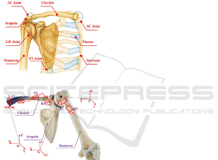
Theoretically, all of the joints and bones of the
shoulder complex that exhibit 6-degree of freedom
(DOF) are particularly complex. Practically
speaking, some researchers, who are just looking for
an equivalent kinematic structure considering the
overall motion characteristics, do not wholly
replicate the shoulder complex. The mechanistic
theory of joint physiology is helpful for
understanding the shoulder complex kinematics
(Maurel, 2000; Lenarčič, 2006; Tondu, 2006).
Figure 1. Anatomy of the shoulder complex.
Figure 2. Mechanism model of the shoulder complex.
For the GH joint has three revolute DOFs with
the axes intersecting vertically in the GH joint center
as well as moves with the functional relevance of the
shoulder girdle during humeral movements and
according to the knowledge of theoretical mechanics,
the general motion of a rigid body can be
decomposed into translation following any of the
base points and rotation relative to the base point.
Thus, the shoulder girdle is assumed to be a platform.
The mobile reference frame is established on the
shoulder girdle, and the origin of the mobile
reference frame is G. Relative to the global
coordinate system: O-XYZ, the G point has three
translational DOFs. The fixed connection coordinate
frame is established on the humerus head, and the
origin, represented by g is a point on the humerus
head coincident with the GH joint center. Relative to
the mobile reference frame, the humerus has three
rotational DOFs with the axes intersecting vertically
in the g point in space. In this way, a generalized GH
joint with floating center (i.e., a 3-DOF spherical
joint with floating center, whose center displacement
variable relative to the sternum is coupled with its
rotation) has been presented, as shown in Figure. 2.
2.2 Detection Mechanism Design
2.2.1 Mechanical Analysis of DOF
According to the model of the shoulder complex, the
GH joint possesses six DOFs (three rotation and
three translation). In order to completely track the
GH joint, the detection mechanism possess three
vertical orthogonal translational joints and three
rotational joints with the axes intersecting vertically
in GH joint center. From the view of the theory of
mechanism, the DOF of the detection mechanism
meets the requirements.
2.2.2 Structure Design of the Detection
Mechanism
The self-tracking mechanical system includes
horizontal tracking mechanism, vertical tracking
mechanism that includes a pulley mechanism, and
wearing mechanism, which are presented in figure. 3.
The function of the self-tracking mechanical system
can be able to fully track the motion information of
the GH joint. The following are the description of
horizontal tracking mechanism, vertical tracking
mechanism, and wearing mechanism in details.
Horizontal tracking mechanism poses two DOFs,
which is mounted on the support plate. It consists of
two interconnected guide strip slide mechanism
which are equivalent to prismatic joints and tracks
the GH joint displacement variable in the horizontal
plane(two guide strip slide mechanism has sufficient
range of motion to track the horizontal motion of the
GH joint).
Vertical tracking mechanism poses one DOF,
which is mounted on the horizontal mechanism. It
consists of one guide strip slide mechanism and a
pulley mechanism. The guide strip slide mechanism
tracks the GH joint displacement variable in the
vertical axis direction, which has sufficient range of
motion to track the vertical axis direction motion of
Detection System Design of the Glenohumeral Joint Motion Information
223
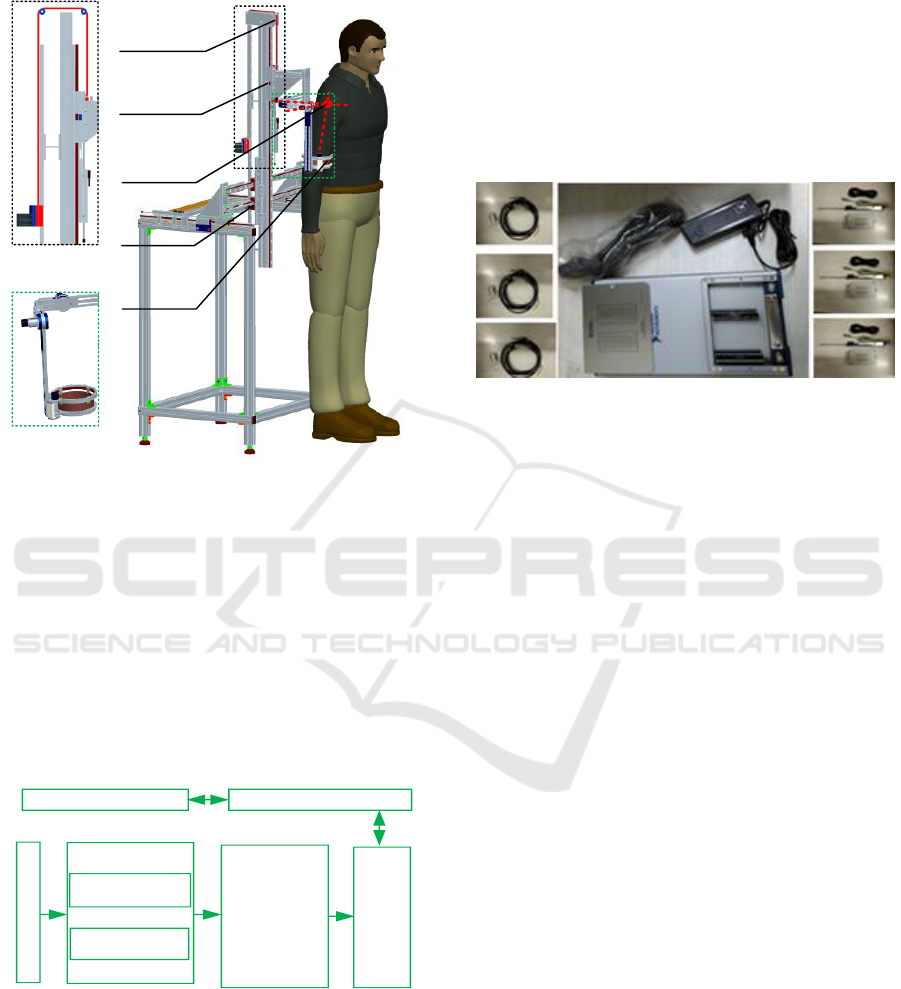
the GH joint. The pulley mechanism can balance the
gravity of the vertical guide strip slide mechanism.
Horizontal
tracking
Wearing
mechanism
Vertical
tracking
Pulley
mechanism
Pulley
mechanism
Glenohume
ral joint
center
Wear
mechanism
Figure 3. Detection mechanism
Wearing mechanism has three revolute DOFs
with the axes intersecting vertically in the GH joint
center, which is mounted on the vertical mechanism.
It consists of three revolute joints which are
connected to each other and is to track three-
dimensional rotation of the GH joint.
2.3 Measurement System Design
Figure. 4 is the measurement system schematic
diagram, which includes the hardware and software.
Detection object
Displacemen
t sensor
Incremental
encoder
Signal
adjustment
module
NI
-
USB
-
6341
Ordinary ComputerLABVIEW
Figure 4. Diagram of measurement system
2.3.1 Hardware of the Measurement System
The hardware mainly includes three displacement
sensors (NS-WY-02), three incremental encoders
(CFZ2124-3600-06-14F), signal adjustment module,
and a collection card of NI-USB-6341. The function
of the displacement sensor is to obtain the
displacement variable of the GH joint in three
dimensions. The incremental encoder is to obtain the
angle motion information of the GH joint during
humerus rotation movement. The signal adjustment
module is to adjust the weak signal of the sensors
and the incremental encoders. The NI-USB-6341 is
to obtain the adjustment signal which can be
transmitted to the ordinary computer via USB port,
the actual components are presented in figure. 5.
Figure 5. Diagrams of components
2.3.2 Software of the Measurement System
The displacement sensor outputs voltage signal and
the encoder outputs digital signal. Thus, this
detection system needs to detect three channels of
analog voltage signals, three channels of digital
signals, and the six channels of signals are required
for synchronous acquisition. The collecting
information of the three encoders use three counters
as well as the information of the three displacement
sensors and synchronous acquisition is a
conventional collection.
Using LABVIEW to develop the underlying
application, specific programming principle is as
follows: First of all, establishment three-way analog
input channels collect voltage signal and
establishment a three-way counter signal acquire
encoder Angle. Using the data line of the error
message to arrange the parallel execution sequence
and the counter to synchronize the trigger signal.
The analog input channel and counter acquisition
channel are set to the same sampling rate and
synchronization trigger counter clock source, so as
to realize synchronization of all signal acquisition.
2.4 Detection System Integration
Combined with the data measurement system
described in the above section, the rotation
information of the GH joint can be obtained through
the connection of the encoder, coupling, and the
detection mechanism; the translation information of
the GH joint can be acquired through the connection
ICVMEE 2019 - 5th International Conference on Vehicle, Mechanical and Electrical Engineering
224
of the displacement sensor and the detection
mechanism. Then, the GH joint motion information
detection system is obtained.
Figure 6. System integration.
The whole system starts from the tested object
and converts it into electrical signal through the
sensor and encoder. After the signal conditioning
module, the signal is sent to the data acquisition card
(NI-USB-6341) for collection and then process by
the software. The data curve in the acquisition
process is displayed on the monitor in real time. The
structure diagram of measurement system and
detection system integration is shown in figures. 4, 6.
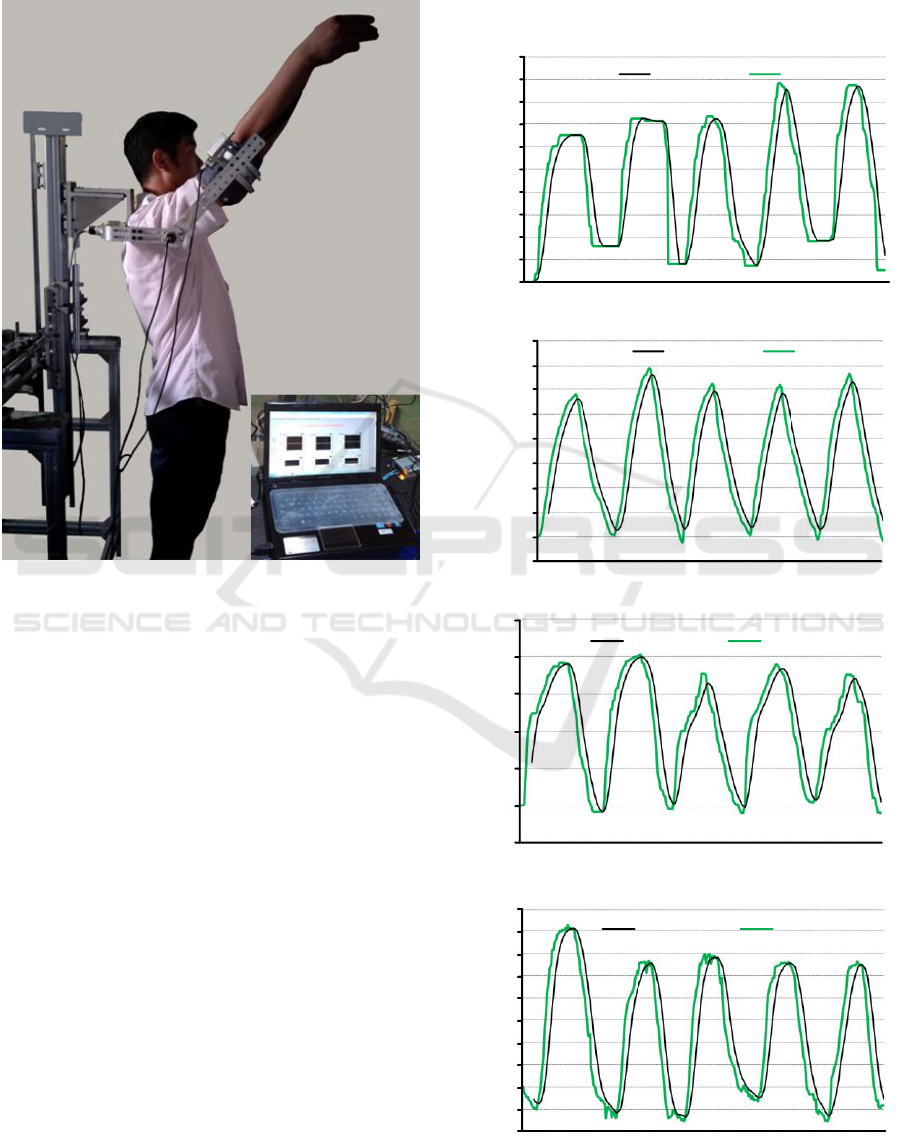
3 TEST AND ANALYSIS
The prototype of the detection system is shown in
Figure. 6. At the beginning of the test, the tester
weared the detection mechanism and the
experimenter made the wearing device's three
rotational joints with the axes intersecting vertically
in GH joint center. Then, the tester rotated humerus
complete the flexion and extension movement in
five cycles, and the detection system presented and
recorded the GH joint motion data. One set of data
was described below: Tester (age 26 years; height
179 mm; weight 82kg; arm length 551.5mm) made
humerus complete the flexion/extension movement
in five cycles. Experimental results, which are the
GH joint motion data during flexion/extension
movement in five cycles, are shown in Figure.7.
0
1
0.2
0.4
0.6
0.8
1.2
1.4
1.6
1.8
Cycle(%)
Adduction and abduction angle(°)
Moving average Data point
2
(a)
-20
80
0
20
40
60
100
120
140
160
Cycle(%)
Flexion and extension angle(°)
Moving average Data point
(b)
-0.5
Moving average Data point
Cycle(%)
Internal and external angle(°)
0
0.5
1
1.5
2.5
2
(c)
-10
Cycle(%)
X Displacement variable quantity(mm)
Moving average Data point
20
15
10
5
0
-5
25
30
35
40
(d)
Detection System Design of the Glenohumeral Joint Motion Information
225
Moving average Data point
-10
-5
-15
5
10
0
20
25
15
35
30
Y Displacement variable quantity(mm)
Cycle(%)
(e)
Cycle(%)
Z Displacement variable quantity(mm)
Moving average Data point
-10
0
10
20
30
40
50
60
70
(f)
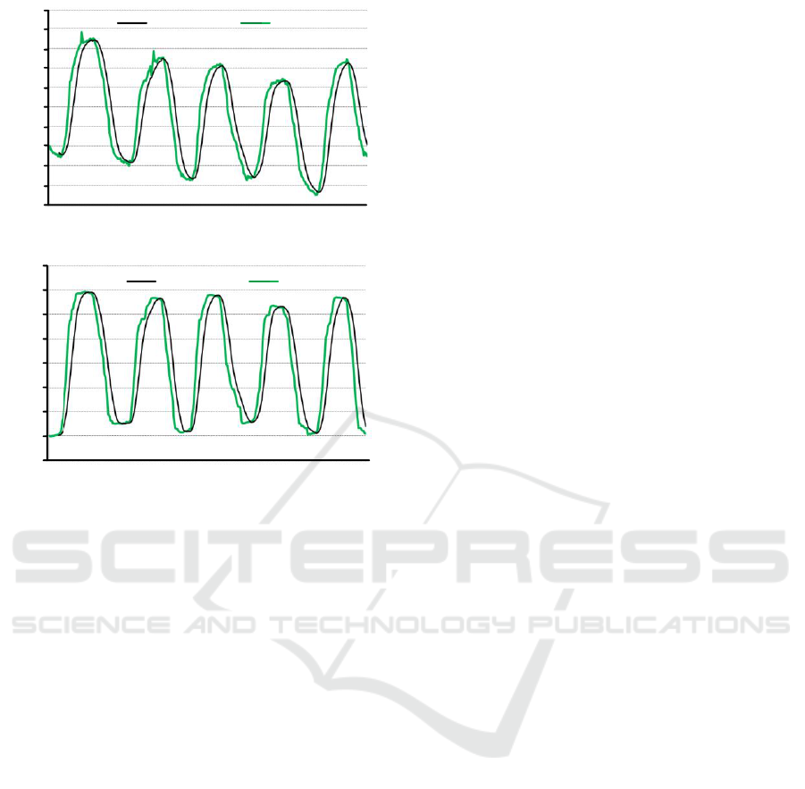
Figure 7. Diagrams of the GH joint motion information
relative to the sternum during humeral natural flexion and
extension rotation in five cycles: (a) humeral adduction
and abduction rotation angle, (b) humeral flexion and
extension rotation angle, (c) humeral internal and external
rotation angle, (d) X of the GH joint displacement variable,
(e) Y of the GH joint displacement variable, (f) Z of the
GH joint center displacement variable.
Fig. 7 shows the green curves (black lines is the
moving average) for the tester performing humerus
flexion/extension nature movement in five cycles
and the angle range is about 120°. The movements
of the GH joint in three dimensionsin
(adduction/abduction, flexion/extension, and
internal/external) and the GH joint center
displacement variable in the X, Y, and Z directions
are observed, which are presented in (a), (b), (c), (d),
(e), and (f), respectively. During the nature
flexion/extension movement of the humerus, a small
amount of adduction as well as abduction and
internal as well as external movement occurs with
the lifting process. This phenomenon is normal
during the natural flexion/extension movement of
the humerus, because it is impossible for the
humerus lifting process to completely guarantee in
the sagittal plane. However, the GH joint center
displacement variable large and regular in the X, Y,
and Z directions confirmed the coupled motion of
the shoulder complex. Subsequently, a great deal of
tests and analyses were performed, the above similar
results are also presented.
4 CONCLUSIONS
In this paper, a kinematic model of the shoulder
complex (3-DOF GH joint with floating center) was
proposed. Then, a detection system was designed.
Real-time GH joint motion information was
obtained, which confirmed the rationality of the
shoulder complex model and detection system.
It provides a method to obtain the movement
information of the GH joint and the detection system
can obtain the fundamental motion data of human
shoulder motion. Which has practical significance
for shoulder function simulation and ergonomics.
ACKNOWLEDGEMENTS
This work was supported by the National Natural
Science Foundation of China under Grants No.
51675008 and No. 51705007, the Beijing Natural
Science Foundation under Grants No. 3171001 and
No. 17L20019.
REFERENCES
B. Tondu, “Modelling of the shoulder complex and
application the design of upper extremities for
humanoid robots”, in Proc. 2005 5th IEEE-RAS Int.
Conf. Humanoid Robots., Tsukuba, Japan, 2006, pp.
313-320.
J. Lenarčič et al, “Positional kinematics of humanoid
arms”, Robotica. vol. 24, no. 1,January, 2006.
J. Yang et al, “Reach envelope of a 9-degree-of-freedom
model,” Int J Rob Autom., vol. 20, no. 4, pp. 240-259,
2005.
K. Kiguchi et al, “Design of a 7DOF upper-limb power-
assist exoskeleton robot with moving shoulder joint
mechanism,” in IEEE Int. Conf. Rob. Biomimetics,
Phuket, Thailand, 2011, pp. 2937-2942.
N. Klopčar and J. Lenarčič, “Bilateral and unilateral
shoulder girdle kinematics during humeral elevation,”
Clin. Biomech. vol. 21, no. supp-S1, pp. 20-26, 2006.
N. Tobias, et al. ARMin III ‒ Arm Therapy Exoskeleton
with an Ergonomic Shoulder Actuation. Appl. Bionics.
Vol. 6 (2009) No. 2, p. 127-142.
R. F. Kirsch et al, “Model-based development of
neuroprostheses for restoring proximal arm function”,
J. Rehabil. Res. Dev, vol. 38, no. 6, pp. 619-626, 2001.
W. Maurel, et al, “Human shoulder modeling including
scapulo-thoracic constraint and joint sinus cones,”
Comput. Graph-uk., vol. 24,no. 2, pp. 203-218, 2000.
ICVMEE 2019 - 5th International Conference on Vehicle, Mechanical and Electrical Engineering
226
