
Establishment and Simulation of the Damping Torque Model of
Hydraulic Intelligent Knee Prosthesis
Jinyue Sun
1, 2, a
, Qiaoling Meng
1, 2, b
, He Lan
1, 2
, Zongqi Jiao
1, 2
and Hongliu Yu
1, 2
1
Institute of Rehabilitation Engineering and Technology, University of Shanghai for Science and Technology, Shanghai
200093, P.R.China
2
Shanghai Engineering Research Center of Assistive Devices, Shanghai 200093, P.R.China
Keywords: Hydraulic, intelligent knee prosthesis, damping torque, dynamics model, simulation.
Abstract: The intelligent knee prosthesis structure was designed and the dynamics model of the lower limb prosthesis
system and hydraulic damper model were established in this paper. The flow area which adjusted the
damping torque was identified through the combination of hydraulic damper model and dynamics model.
The comparable analysis was done based on the Matlab simulation of damping torque curve with theoretical
curve. The damper opening of the specific speed was determined. The trend of the knee joint moment curve
produced by the hydraulic damper is consistent with the theoretical moment curve under different flow areas.
The damping moment of hydraulic knee joint can be controlled by adjusting the flow area. The proposed
damping torque model can provide effective guidance for the determination of the flow area and have
important consequences for adjustment of damping torque. Providing theoretical model of the damping
torque control for the hydraulic intelligent knee prosthesis.
1 INTRODUCTION
Human gait can be divided into two periodic
repeating phases: stance phase and swing phase. The
function of the above-knee prosthesis is to maintain
the stability of the knee in the stance phase and
provide essential damping in the swing phase (Kun
Shang, et al., 2009). Therefore, prosthetic knee joint
is the most important and complex component of the
above-knee prosthesis. Knee torque limits whether
the maximum knee flexion is close to the
physiological gait. And it determines whether the
shank can decelerate smoothly until knee fully
extend and the magnitude of the ground impact
when the heel strikes the ground. Inappropriate knee
torque control will lead to abnormal gait, reduce gait
symmetry, and increase energy consumption of the
wearer (Chunxia Zhao et al., 2015). The control of
knee joint moment can be divided into three kinds:
constant friction, mechanical spring and damper
control. The control mechanism is that the moment
curve generated at the knee joint is close to the
moment curve under the physiological gait, so that
the shank swing is close to the physiological gait
(Yanli Geng et al., 2013). According to whether the
knee joint can produce active moment, the knee
prosthesis can be divided into active prosthesis and
passive prosthesis. Passive knee prosthesis uses
pneumatic pressure, hydraulic pressure,
magnetorheological and other dampers to generate
damping torque, while active knee prosthesis
generates active torque through motor, pneumatic
muscle, micro hydraulic pump and so on. Intelligent
knee joint refers to the application of microcomputer
technology and intelligent control technology to the
control of knee joint damper, so that the knee joint
torque can be automatically adjusted with the change
of walking speed and joint angle in order to make
the gait symmetry and tracking more closely to
healthy people (Tengyu Zhang et al., 2016).
The control of knee torque is always the
importance and difficulty of research. Dundass
studied the effect of degradation of the hydraulic
damper on a patient's gait. In order to eliminate the
influence of variables on gait in the gait experiment,
a dynamic model was established based on the gait
data of patients in the experiment. The ground
reaction force predicted by this dynamic model is
consistent with the experimental data. However, the
drawback is that the model is only for one
experimental patient, and it is not universal
(Dundass et al., 2003). Furse improves the control
Sun, J., Meng, Q., Lan, H., Jiao, Z. and Yu, H.
Establishment and Simulation of the Damping Torque Model of Hydraulic Intelligent Knee Prosthesis.
DOI: 10.5220/0008856302030209
In Proceedings of 5th International Conference on Vehicle, Mechanical and Electrical Engineering (ICVMEE 2019), pages 203-209
ISBN: 978-989-758-412-1
Copyright
c
2020 by SCITEPRESS – Science and Technology Publications, Lda. All rights reserved
203
performance of swing phase torque by adding two
series springs to the friction brake single-axis
passive knee prosthesis, but it is difficult to apply to
the intelligent knee prosthesis with hydraulic and
pneumatic control (Furse et al., 2011). Based on the
concept of energy flow in human gait, Unal
proposed the passive control mechanism of reducing
energy consumption of swing phase by using three
elastic energy storage elements (Unal et al., 2010).
Dabiri designed a passive hydraulic damping
controller for swing phase of uniaxial knee
prosthesis, but the experimental results show that the
maximum flexion angle controlled by the damper is
quite different from that of normal people, and the
control effect is not ideal (Dabiri et al., 2009).
Tahani and Karimi proposed a dynamic model of
lower limb prosthesis based on torsion spring control,
and optimized the control parameters of swing phase
motion (Tahani et al., 2010). Suzuki optimized the
dynamics of the musculoskeletal model of the stump
to obtain the friction value of the passive knee
prosthesis and minimize the energy consumption of
the swing muscle (Suzuki, 2010). Based on the
control parameters of nonlinear hydraulic damper,
Hongliu Yu proposed a dynamic model of swing
phase for intelligent lower limb prosthesis, and the
dynamic relationship between the opening of
damper needle valve and the velocity of swing phase
is identified. But this research model think the
velocity of damper piston is constant, and it is
different from the actual piston velocity (Hongliu Yu
et al., 2010).
Domestic and foreign researchers have proved
the feasibility of the application of damper in the
torque control of knee prosthesis. However, there are
still relatively few studies on the design of
appropriate intelligent knee prosthesis structure, the
construction of dynamic model of the complete
system composed of knee damper and stump, and
the evaluation of the torque control performance of
intelligent knee prosthesis. This study designs a kind
of intelligent knee prosthesis with hydraulic damper
and establishes the dynamic model of the lower limb
prosthesis system and the coupled hydraulic damper
damping torque model. In this study, the torque
control of the knee prosthesis of the dynamic model
is simulated by Matlab, and the effectiveness of the
damping torque model and the rationality of the
designed intelligent knee prosthesis hydraulic
damper structure are proved.
2 MATERIAL AND METHODS
The function of the knee prosthesis is to maintain
stability in the stance phase and provide proper
damping in the swing phase. At present, the damper
used in intelligent knee prosthesis is mainly
hydraulic control, pneumatic control,
magnetorheological control and hydraulic and
pneumatic hybrid control. Pneumatic damping is
small. So it is difficult to guarantee the stability of
the stance phase and commonly used in multi-axis
knee prosthesis. Magnetorheological fluid damper
changes the magnetic field intensity and the
viscosity of fluid by changing the current, so the
damping force at the knee prosthesis is changed to
control the moment of knee prosthesis. But the
control mechanism of magnetorheological fluid
viscosity changes still need to be researched. In
addition, it cannot be close to places with strong
magnetic and electric fields, which limits the range
of use. Hydraulic damper can provide strong
damping when the volume is small, which can
effectively ensure the stability of the stance phase.
So it is mostly used for uniaxial knee prosthesis
(Wujing Cao et al., 2016).
2.1 Structural Design of Knee
Prosthesis
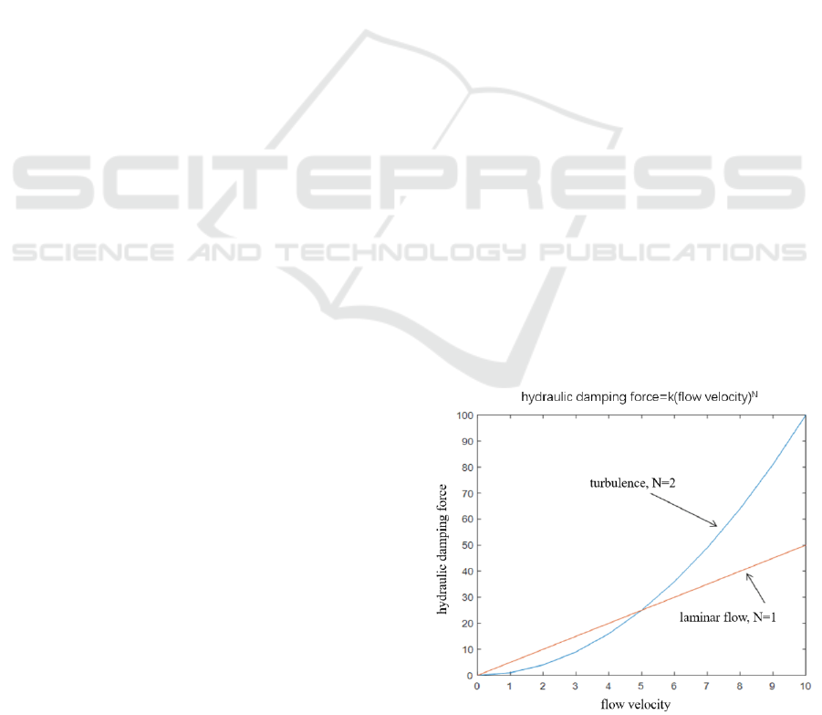
Hydraulic damping force presents different
properties with the change of hydraulic fluid
velocity. When the flow velocity is slow, the
damping and velocity are linear, that is, the damping
is proportional to the flow velocity. When the
velocity is large, the increase of damping is
nonlinear, that is, damping is proportional to the
Figure 1. Relation of flow speed and damping force.
ICVMEE 2019 - 5th International Conference on Vehicle, Mechanical and Electrical Engineering
204

Figure 2. Knee prosthesis structure.
square of velocity (Staros & Murphy, 2013). When
the hydraulic oil flows through the small hole in the
circular tube in laminar flow state, the flow velocity
will increase instantly due to the sudden decrease of
flow area, resulting in turbulence. The relationship
between hydraulic damping force and flow velocity
change is shown in Fig. 1. This property makes it
possible to adjust the damping force of knee joint at
different speeds by changing the flow area of
hydraulic fluid. And then it changes the velocity of
hydraulic oil to create turbulence to achieve rapid
adaptation and control of damping torque. This is
very beneficial to the acquisition of the
physiological gait of the knee swing phase.
Therefore, uniaxial hydraulic knee joint structure is
selected (Hongliu Yu et al., 2009). In order to realize
the independence of intelligent knee flexion and
extension damping torque control, two motors are
used to control the corresponding plug valve
respectively. The flow area of the oil passage is
changed by the DC motor rotating plug valve, so
that the flow rate of the hydraulic oil is
instantaneously increased to form turbulent flow and
cause pressure loss. And then it controls the pressure
difference between the upper and lower chambers to
generate the damping force so as to achieve the
control of the knee damping torque at different
speeds. The overall knee structure is shown in
Figure 2. In order to ensure that the damping of the
flexion oil passage and the extension oil passage do
not affect each other, a check valve is placed in each
of the two oil passages. When the knee is flexed and
the hydraulic piston moves downward, the check
valve in the extension oil passage is closed and the
check valve in the flexion oil passage is opened.
And then the hydraulic oil can only enter the upper
chamber from the lower chamber through the flexion
adjustment oil passage. When the knee is extended
and the hydraulic piston moves upward, the check
valve in the flexion oil passage is closed and the
check valve in the extension oil passage is opened.
And then the hydraulic oil can only enter the lower
chamber from the upper chamber through the
extension adjustment oil passage. In order to assist
the knee extension, a spring is placed in the bottom
of the hydraulic cylinder. In each phase state, the
opening of the hydraulic damper valve is controlled
to adjust the flow rate of the hydraulic oil and then
control the knee damping torque. The magnitude of
the damping torque is proportional to the square of
the knee angular velocity.
2
=M CV
(1)
M is the knee damping torque, V is the knee
angular velocity obtained by deriving the knee angle
signal, and C is the knee dynamic damping constant.
Five valve opening degrees, namely five different
damping constant values, are controlled during a
given walking cycle to achieve five phase
adaptations and adjustments. The damping value is
adjusted only when the gait phase transforms or the
period changes, and the damping constant is not
adjusted within a certain gait phase. The purpose of
the intelligent knee prosthesis adaptive control
system is to determine the damping constant which
is adapted to the phase state, that is, to control the
appropriate valve opening when the state transforms,
and then the physiological gait is achieved.
2.2 Dynamic Modeling of Lower Limb
Prosthetic System
The uniaxial knee prosthesis is connected to the
wearer's thigh stump through the prosthetic socket.
In order to design the knee controller, the thigh
motion experimental data is provided to the system
dynamics model to obtain the expected knee
damping torque curve. The damping torque curve
actually provided by the hydraulic damper is
obtained by adjusting the flow area of the hydraulic
damper in Matlab. The difference between the
simulation curve and the theoretical curve is
analyzed and compared, and the optimal flow area of
the hydraulic damper at different speeds is obtained.
The dynamic model is validated to provide
theoretical guidance for the control of the knee joint
damping torque.
The dynamic model of incorporating the
hydraulic damper into the lower limb prosthetic
system is shown in Fig. 3. The lower limb prosthetic
system of the amputated patient can be simplified
Establishment and Simulation of the Damping Torque Model of Hydraulic Intelligent Knee Prosthesis
205
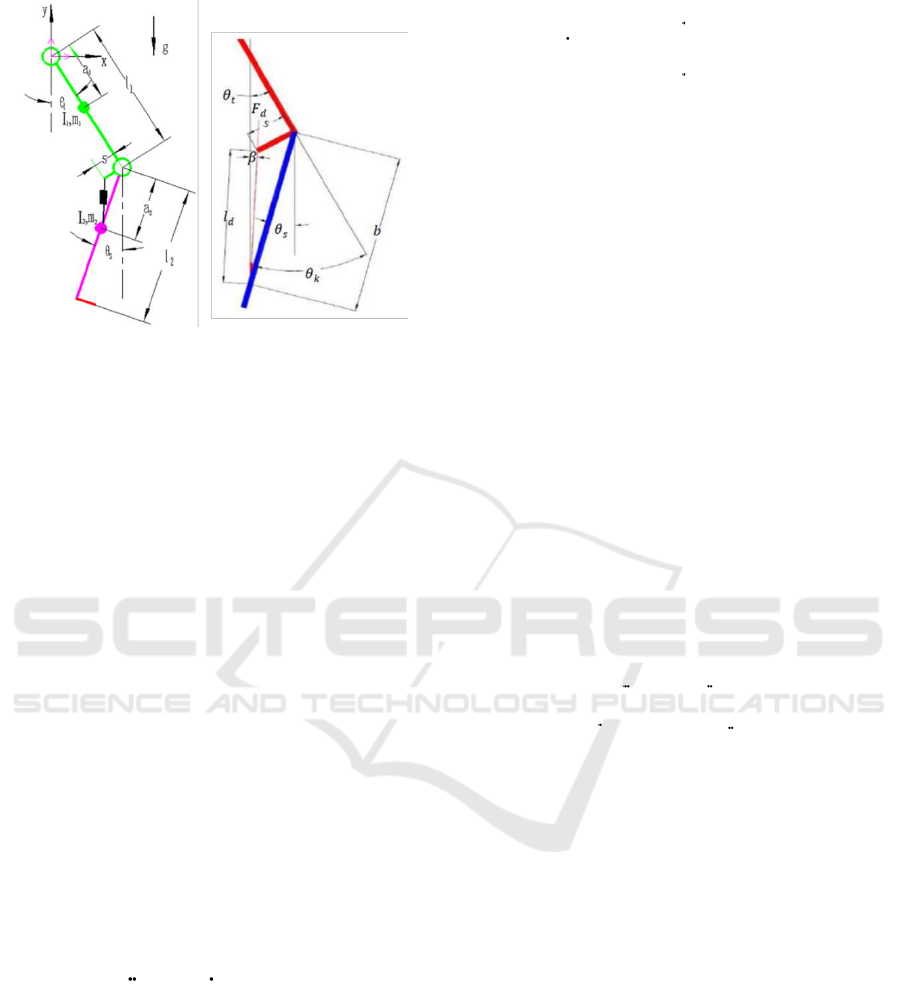
Figure 3. Dynamics model of lower limb prosthesis.
into a two rigid body model, which represents the
movement of the thigh and the calf in the sagittal
plane. The foot and leg tube are equivalent to a rigid
connection. In Fig. 3, subscripts 1 and 2 represent
the thigh and calf parameters respectively.
i
m
represents the mass.
i
a
represents the distance from
the centre of mass to the rotating joint.
i
I
represents the rotational inertia.
t
and
s
represent the angle between the thigh and the calf
and the vertical direction, respectively.
k
represents the knee angle.
d
l
represents the length
of the damper.
s
represents the distance between
the centre of knee rotation and the connection point
on the piston rod of the hydraulic damper.
b
represents the distance between the centre of knee
rotation and the joint point of the damper under the
leg tube.
1
T
represents hip torque.
Assuming that there is no friction between joints,
the second type of Lagrange equation is used to
establish the dynamic model (Xiaodong Wang et al.,
2015).
( ) ( + ( )D C G
,)
(2)
Inertial matrix is given by
22
1
1 1 2 1 2 1 2
2
2
2 1 2 2 2
cos( )
()
cos( )
ts
ts
D
ma m l m l a
I
m l a m a
I
(3)
Coriolis force and centrifugal force influence
coefficient matrix is given by
2
2 1 2
2
2 1 2
( ) sin( )
( , )
( ) sin( )
s
ts
t
ts
C
m l a
m l a
(4)
Gravity torque parameter matrix is given by
1 1 2 1
22
sin( ) sin( )
()
sin( )
tt
s
gg
G
g
m a m l
ma
(5)
Hip and knee parameter matrix is given by
1
sin( )
sin( )
d
s
d
s
b
b
TF
F
(6)
Thigh and calf angle vector matrix is given by
t
s
(7)
In the calculation of the dynamic equation of
lower limb movement, the hip torque and the thigh
angle produced by a normal person are known inputs.
Knee torque determined by Lagrange equation can
be expressed as follows:
2
2 2 1 2
2
2
2
2 1 2 2 2
'
cos( )
sin( ) sin
s t t s
t t s s s
k
g
m
a m l a
M
m l a m a
I
(8)
2.3 Hydraulic Damper Model
The hydraulic damper is a spring damper system. It
generates a real-time varying damping torque when
the knee prosthesis moves, so that the maximum
angle of the knee can be controlled at different
speeds to achieve physiological gait (Siyuan Gong et
al., 2010). The change of the hydraulic damping
torque is achieved by adjusting the opening of the
damper valve. The knee damping torque actually
generated by the hydraulic damper is given byx
( )L
kd
kx
MF
(9)
k
is extension spring modulus, and
x
is
spring compression. Real-time moment arm length
can be expressed as follows:
ICVMEE 2019 - 5th International Conference on Vehicle, Mechanical and Electrical Engineering
206
22
cos( )
2 sin( )
st
st
bs
L
bs
bs
(10)
Hydraulic damper pressure difference between
upper and lower chamber is
P
, and the effective
action area of the piston is
A
. Hydraulic damping
force can be expressed as follows:
d
PA
F
(11)
Damper piston velocity is
V
. When hydraulic
oil flows through the valve, the effective flow area is
0
A
. Flow coefficient is
d
C
. And Hydraulic oil
density is
. So
P
can be expressed as follows:
2
2
2
2
0
2
d
P
V
A
C
A
(12)
The length of the damper
d
l
is a variable during
the movement. It can be expressed as follows:
22
2 sin( )
d s t
bs
l b s
(13)
Damper piston velocity is given by
22
cos( )( )
2 sin( )
st
st
d
st
bs
Vl
bs
bs
(14)
So the knee damping torque actually generated
by the hydraulic damper is given by
2
3
2
2
22
0
cos( )
()
2
2 sin( )
st
k
d
st
bs
kx
bs
V
A
M
C
A
bs
(15)
And then the knee damping torque actually
generated by the hydraulic damper can be expressed
as follows:
22
3
22
2 2 2
2
0
22
cos ( ).( )
()
2 ( 2 sin( )
cos( )
2 sin( )
s
s t t
k
d s t
st
st
kx
bs
bs
bs
bs
A
M
C b s
A
bs
(16)
Coupling the knee torque determined by the
kinetic equation with the torque provided by the
hydraulic damper is given by
'
kk
MM
(17)
When the knee geometric parameters and human
body parameters are determined, the hip and knee
angle information are measured and the real-time
valve flow area can be obtained. However, due to
the short time of a gait cycle, if the motor is used to
drive the valve to make the real-time change of the
area completely and track the matching theoretical
torque curve in actual operation, speed adjustment
will be too late and power consumption will be fast.
Therefore, the following simulation simulates the
actual torque curve and the theoretical torque curve
generated by several fixed flow areas at a walking
speed, and compares the analysis curve to determine
the most suitable flow area at this speed. The area
data is stored. And when the sensor detects the
walking speed of the wearer, the stored data can be
directly called.
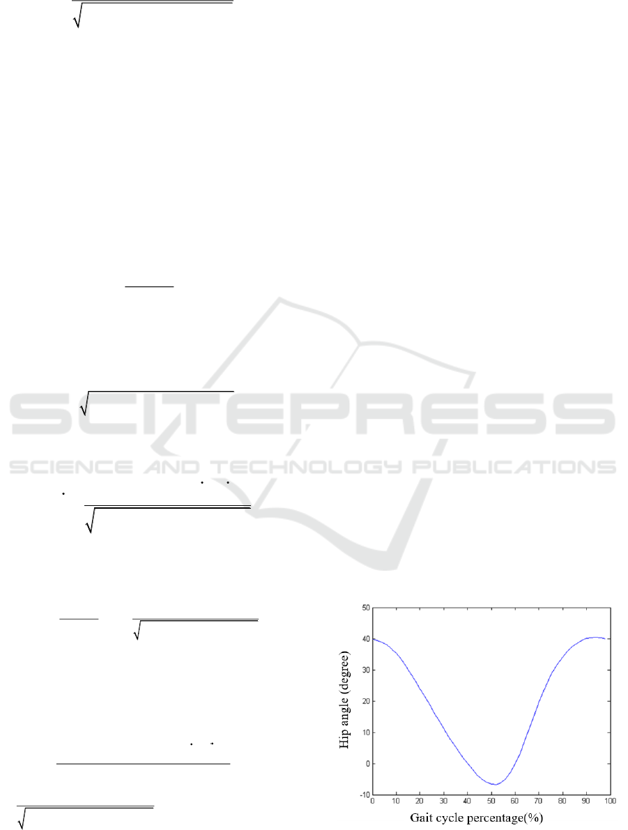
2.4 Damper Torque Simulation
Using the hip and knee angle information of a
healthy person at a walking speed, the damping
torque curve required by the Lagrangian equation is
obtained by Matlab. The damping torque curve
actually provided by the hydraulic cylinder is
obtained by Matlab under the same conditions
different flow conditions, and then the best flow area
0
A
under this walking speed is obtained. In this
way, the optimal flow area under different walking
speeds is obtained in turn. The parameters of the
lower limb prosthesis system are designed as follows:
Figure 4. Hip angle input.
Establishment and Simulation of the Damping Torque Model of Hydraulic Intelligent Knee Prosthesis
207
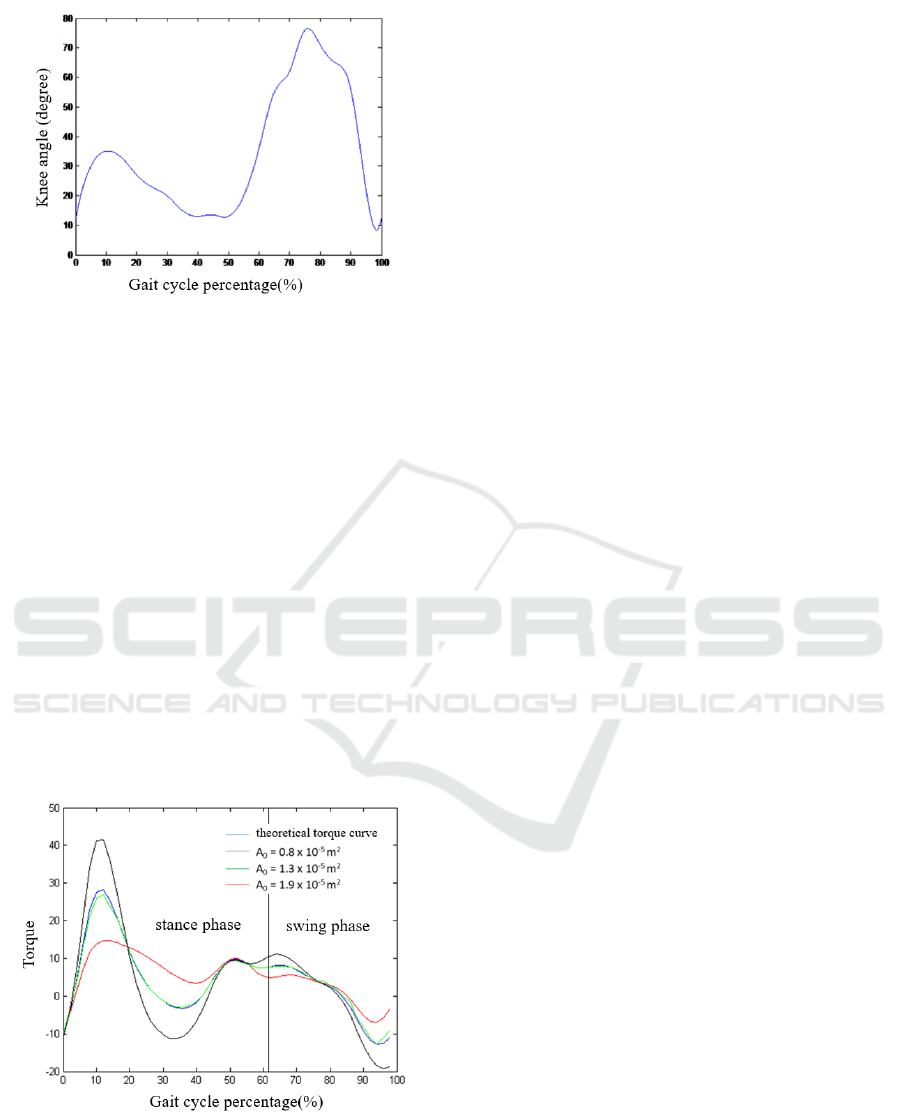
Figure 5. Knee angle input.
1
9.9kg
m
,
2
2.6kg
m
,
1
0.55m
l
,
2
0.4m
l
,
1
0.267m
a
,
2
0.176m
a
,
2
1
0.031 .kg m
I
,
2
2
0.0032 .kg m
I
,
3
870 /kg m
,
42
5.37 10Am
,
0.185bm
,
0.02sm
,
0.7
d
C
,
3
1.4 10 /k N m
. The walking experimental data
of the normal person was obtained from the
literature (Matinmanesh & Mallakzadeh, 2011). And
the hip angle curve and the knee angle curve are
shown in Fig. 4 and Fig. 5, respectively.
The theoretical calculation of the knee joint
torque curve and the flow area
0
A
are respectively
taken
52
0.8 10 m
,
52
1.3 10 m
,
52
1.9 10 m
,
and the hydraulic damper actually provides the
torque curve as shown in Fig. 6.
It can be seen from the figure that under different
flow areas, the overall trend of the
Figure 6. Knee theoretical torque and damping torque in
different flow area.
hydraulic damping torque curve is consistent
with the theoretical torque curve. When
0
A
is
52
1.3 10 m
, the simulated knee torque is closest to
the theoretical torque curve. So this flow area can be
used as a preset flow area at this speed.
3 DISCUSSION
The torque required for the knee prosthesis at
different speeds are different. The control of the
knee damping torque is realized by the damper to
realize the tracking speed of the wearer. The
adjustment of the hydraulic knee damping force is
achieved by changing the flow area of the upper and
lower chambers of the hydraulic cylinder, and the
specific traveling speed corresponds to a specific
optimal flow area. As the flow area increases, the
damping force decreases nonlinearly. And when the
walking speed is constant, there is always a
corresponding optimal flow area. The theoretical
simulation results verify the correctness of the
kinetic model for knee damping torque control.
Since the modeling parameters are taken from
healthy people, the actual application will inevitably
produce a certain deviation. For specific lower limb
amputation patients, data from healthy people with
similar body size can be used as initial data for
prosthetic wearers. After the prosthesis is worn, the
angle information of the wearer's healthy leg and the
knee parameters are recalculated to obtain an
optimized opening degree.
4 CONCLUSIONS
In this study, a dynamic model of the lower limb
prosthetic system was established by designing an
intelligent knee joint structure. The coupling of the
hydraulic damper and the system dynamics model is
used to determine the flow area of the knee damping
torque. The Matlab-based simulated damping torque
curve is compared with the theoretical curve to
determine the knee damper opening at the tester's
specific speed. The following results are obtained
from the simulation:
(1) The relationship between hydraulic damping
and flow rate determines its superiority for knee
joint damping torque control. The hydraulic
damping torque curve can be obtained by changing
the flow area of the valve. By comparing and
analyzing the theoretical knee torque curve and the
hydraulic damping torque curve, the optimal flow
area at a specific speed can be obtained.
ICVMEE 2019 - 5th International Conference on Vehicle, Mechanical and Electrical Engineering
208

(2) As the flow area increases, the knee joint
damping torque gradually decreases. The optimal
flow area at different speeds can be simulated
multiple times by using the measured hip and knee
angle curves as input data.
(3) The knee damping torque curve under the
optimal flow area obtained by the simulation has a
small deviation from the theoretical curve, but the
change trend is basically consistent with the
theoretical curve. The correctness of the kinetic
model is verified and can be optimized by replacing
the data of healthy people with the wearer's own
measured data.
REFERENCES
Chunxia Zhao, Ting Liu, et al., 2015. Design and
evaluation of an overall unloading knee brace. Journal
of Medical Biomechanics 30(6): 564-568.
Dundass C., Yao, et al., 2003. Initial Biomechanical
Analysis and Modeling of Transfemoral Amputee Gait.
Jpo Journal of Prosthetics & Orthotics 15(1):20-26.
Dabiri Y., Najarian S., et al., 2009. Passive Controller
Design for Swing Phase of a Single Axis Above-Knee
Prosthesis. Iranian Journal of War & Public Health
1(3):76-87.
Furse A., Cleghorn W., Andrysek J., 2011. Development
of a low-technology prosthetic swing-phase
mechanism. Journal of Medical & Biological
Engineering 31(2):145-150.
Hongliu Yu, Jiahua Hu, et al., 2010. Dynamics modelling
of artificial legs system based on knee joint damper
characteristics. Journal of Machine Design 27(2):40-
42.
Hongliu Yu, Ling Shen, et al,.2009. Design of electro-
nically controlled hydraulic damper for prosthetic
knee. Journal of Clinical Rehabilitative Tissue
Engineering Research 13(39):7635-7638.
Kun Shang, Lixing Shen, et al., 2009. Realization of
kinematics simulation software for four-bar artificial
limb knees. Journal of Medical Biomechanics 24 (2):
107-111.
Matinmanesh A., Mallakzadeh M., 2011. Inverse kinetic
and kinematic analysis of drop-foot patient's walking.
E-Health and Bioengineering Conference (EHB).
IEEE, 2011:1-4.
Suzuki Y., 2010. Dynamic optimization of transfemoral
prosthesis during swing phase with residual limb
model. Prosthetics & Orthotics International
34(4):428-38.
Staros A., Murphy E.F., 2013. Properties of fluid flow
applied to above-knee prostheses. Journal of
Rehabilitation Research & Development 50(3): XVI-
XVI.
Siyuan Gong, Peng Yang, et al., 2010. Development of
intelligent lower limb prostheses based on iterative
learning control: A follow of normal walking speed.
Journal of Clinical Rehabilitative Tissue Engineering
Research 14(13):2295-2298.
Tengyu Zhang, Yubo Fan, 2016. Motion recognition based
on EMG signals of residual limb in transfemoral am-
putee. Journal of Medical Biomechanics 31(6).
Tahani M., Karimi G., 2010. A New Controlling
Parameter in Design of Above Knee Prosthesis. World
Academy of Science Engineering & Technology,
2010(70):926.
Unal R., Carloni R., Hekman E.E.G, et al., 2010. Bio-
mechanical conceptual design of a passive
transfemoral prosthesis. Conf Proc IEEE Eng Med
Biol Soc 2010(10):515-8.
Wujing Cao, Hongliu Yu, et al., 2016. Research on intel-
igent knee joint control method based on different
signal sources. Chinese Journal of Rehabilitation
Medicine 31(10):1129-1132.
Xiaodong Wang, Chunhui Wang, et al., 2015. Bio-
mechanical simulation model of upper limb interaction
for human-spacesuit system. Journal of Medical
Biomechanics 30(6): 540-546.
Yanli Geng, Peng Yang, et al., 2013. Data acquisition and
motion simulation of lower limb. Journal of Medical
Biomechanics 2013, 28(2).
Establishment and Simulation of the Damping Torque Model of Hydraulic Intelligent Knee Prosthesis
209
