
Design of Lubrication and Cooling Flushing Mechanism for Hand-
held Pneumatic Rock Drill
Yueyong Wang
1, 2, a
, Yimin Zhang
1, 2, b
, Zunling Du
1, 2
, Shijie Wang
1
1
School of Mechanical Engineering, Shenyang University of Technology, Shenyang, Liaoning 110870, China
2
Institute of Equipment Reliability, Shenyang University of Chemical Technology ,Shenyang, Liaoning 110142, China
Keywords: Pneumatic rock drill, lubrication mechanism, cooling flushing mechanism.
Abstract: The advantages and disadvantages of the traditional lubrication and cooling mechanism of Air-leg Rock
drill are analyzed. In order to solve the shortcomings of the traditional structure and the fatal disadvantages
of gas-water linkage failure and hammer washing, a new lubrication and cooling mechanism of Air-leg
Rock drill is designed. It prevents the backfilling of pneumatic rock drill in the normal working process and
at the end, improves the life of pneumatic rock drill as a whole, and has been verified in the customer site,
and achieved good results.
1 INTRODUCTION
Pneumatic rock drills used in mining, railway and
highway construction generally work in open pits,
tunnels or mountainous areas (Liu Enguo., 2013).
When the pneumatic rock drill works, there is
relative movement between the head and the rotating
sleeve and between the piston and the rotating nut. It
is easy to wear and tear (Chen Bingzhi, 1987).
Insufficient lubrication is one of the reasons that
often cause the failure of rock drill and parts damage
(Class B, Grade, 1979). Because of the change of
working condition of rock drill, water pressure also
changes, which can't guarantee that water pressure is
always lower than air pressure. In the water washing
mechanism of conventional pneumatic rock drill,
water pressure in water needle can't be adjusted.
Reverse irrigation during normal working process
and at the end of pneumatic rock drill will destroy
the lubrication system of pneumatic rock drill,
accelerate wear and tear, reduce the service life of
parts, and also reduce the machine torque. Drilling
efficiency decreases (Liu Jian, et.al, 2015).
2 CURRENT LUBRICATION
MECHANISM
Air leg rock drill needs lubricating oil for three
purposes: reducing friction, anti-corrosion and
sealing clearance. At present, pneumatic rock drill
has three parts that need lubrication (Yang
Wansheng, 2008): spline pair, brazing tail pair, head
and rotating sleeve matching pair. The lubrication
oil supply of pneumatic rock drill depends on the
exhaust of the front chamber of the cylinder, and the
residual air of compressed air containing atomized
oil passes through the friction pair parts mentioned
above. There are two ways of drainage (Cai Shumei,
2002):
One is the single drainage mode, and the
compressed air residual flow through the spline pair
gap, through a narrow way, flows through the
brazing tail pair and the head and the rotating sleeve
matching pair, leading to the atmosphere. It is
simple in structure, but when the rock drill is
operated under heavy load, because of less gas
flowing through and less atomized oil, it causes poor
lubrication and shortens the service life of the rock
drill.
The other is double drainage and compressed air
surplus through spline pair, which only leads to
brazing tail pair. In addition, a drainage air passage
is provided to lubricate the matching pair of the head
and the rotating sleeve. Its structure is complex and
the lubrication condition of the spline pair becomes
worse due to the reduction of compressed air surplus
flowing through the spline pair, which will also
shorten the service life of the rock drill.
172
Wang, Y., Zhang, Y., Du, Z. and Wang, S.
Design of Lubrication and Cooling Flushing Mechanism for Hand-held Pneumatic Rock Drill.
DOI: 10.5220/0008849001720174
In Proceedings of 5th International Conference on Vehicle, Mechanical and Electrical Engineering (ICVMEE 2019), pages 172-174
ISBN: 978-989-758-412-1
Copyright
c
2020 by SCITEPRESS – Science and Technology Publications, Lda. All rights reserved
3 CURRENT COOLING AND
FLUSHING MECHANISM
In the working process of air leg rock drill, water
will supply water needle, through drill rod, to reach
the bottom of the hole, water will be used to cool
and wash the rock powder at the bottom of the hole
to achieve the purpose of dust and powder discharge
(Liu Guangwen, Wang Yueyong, Liu Enguo, 2018).
Ideally, when the Air-leg Rock drill works, the water
pressure of the water needle should be lower than
the air pressure. If the water pressure in the water
needle is higher than the air pressure, the water flow
will enter the air passage and cylinder block,
destroying the oil film of the moving parts, thus
affecting the normal work of the rock drill. When
the water pressure in the water needle is higher than
the air pressure, the water will be poured back into
the air channel. The water washing mechanism of
the existing pneumatic rock drill can not regulate the
water pressure in the water needle, and can not
guarantee that when the water pressure is higher
than the air pressure, the water pressure can be
regulated below the air pressure.
Therefore, there is a rigid requirement in the use
of air leg rock drill: the working pressure must be
lower than the working pressure. Excessive water
pressure can easily cause gas-water linkage (water
injection valve) failure; in particular, backfilling will
occur, which will cause air-water mixing to appear
"wash hammer" and destroy lubrication; there will
also be some disadvantages such as ice in silence
cover. The general water pressure is between 0.2
MPa and 0.3 MPa.
4 NEW DESIGN OF
LUBRICATION MECHANISM
In order to solve the above problems (Luo
Liangguang, 2008), a new design scheme of
lubrication mechanism is proposed.
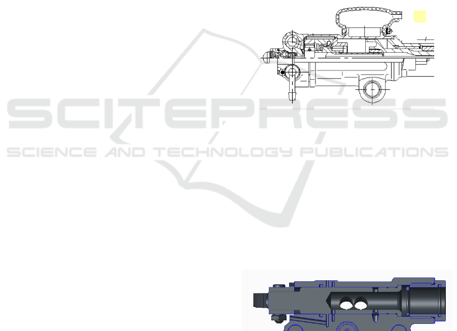
The lubrication of the new air leg rock drill
consists of a control valve, a handle, a cylinder block,
a guide sleeve and a head (see Figure 1). The control
valve is arranged in the handle body. A strong blow
hole is opened on the control valve and a handle
hole is arranged on the handle body. In the position
of the strong blow hole of the control valve, an
annular groove is opened along the radial direction
of the control valve. When the pneumatic rock drill
enters the compressed air (oil), the compressed air
(oil) enters the nose of the pneumatic rock drill
through the annular groove of the control valve
along the handle channel, cylinder block channel,
guide sleeve channel and the nose hole. The width of
the annular groove is 2 mm and the depth of the
annular groove is 0.5 mm. After compressed air
(containing oil) enters the head, it passes through the
gap between the head and the rotating sleeve and
forms oil film to realize lubrication function. Then it
enters the body of the rotating sleeve through the
hole of the rotating sleeve, passes through the gap
between the rotating nut and the piston and forms oil
film to realize lubrication function. At the same time,
the gas forms a pressure chamber in the head, and
the pressure in the pressure chamber is higher than
the water pressure, thus preventing water from
drilling. The center hole of the rod is poured back
into the pneumatic rock drill.
Figure 1. New lubrication mechanism diagram.
5 NEW DESIGN OF COOLING
AND FLUSHING MECHANISM
The cooling and flushing mechanism of the air leg
rock drill (see figure 2) includes a water valve body
and a pressure regulating device that allows the
valve body to move to a fixed position to control the
opening and closing of water flow in the water
needle.
Figure 2. Drawing of New Cooling and Flushing
Mechanism.
The valve body contains a passage for opening
the valve at preset pressure and allowing water flow
to pass through; together with the valve, it can
prevent the water pressure in the needle from
Design of Lubrication and Cooling Flushing Mechanism for Hand-held Pneumatic Rock Drill
173
exceeding the preset pressure, and the valve can
open freely without pressure resistance.
The water valve contains a passage that allows
the water pressure in the water needle to enter the
other end of the valve. When the water pressure in
the water needle exceeds the preset pressure, the
water valve moves towards the closing direction,
controls the water flow into the water needle, and
adjusts the water pressure in the water needle.
A spring is placed at the other end of the valve,
which can drive the valve to move in the direction of
closure; the valve contains a passage that allows
water from the needle to enter the other end of the
valve, so that the valve closes before the pressure
exceeds the preset pressure to prevent the pressure
from exceeding the preset pressure. When the rock
drill stops working, the spring can push the water
valve to the closed state and stop the water supply.
6 APPLICATION OF NEW
INSTITUTIONS AND
CONCLUDING REMARKS
The new lubrication mechanism of pneumatic rock
drill improves the structure of control valve,
optimizes the strong blow and lubrication channel of
handle, cylinder block, guide sleeve and head, thus
effectively improves the lubrication effect of
pneumatic rock drill.
The new cooling and flushing mechanism of Air-
leg Rock drill can ensure that the water pressure in
the water needle is lower than the air pressure in the
working process of rock drill, prevent water from
backfilling into the body, destroy the oil film of
parts and components, and lead to corrosion or
abrasion of parts and components.
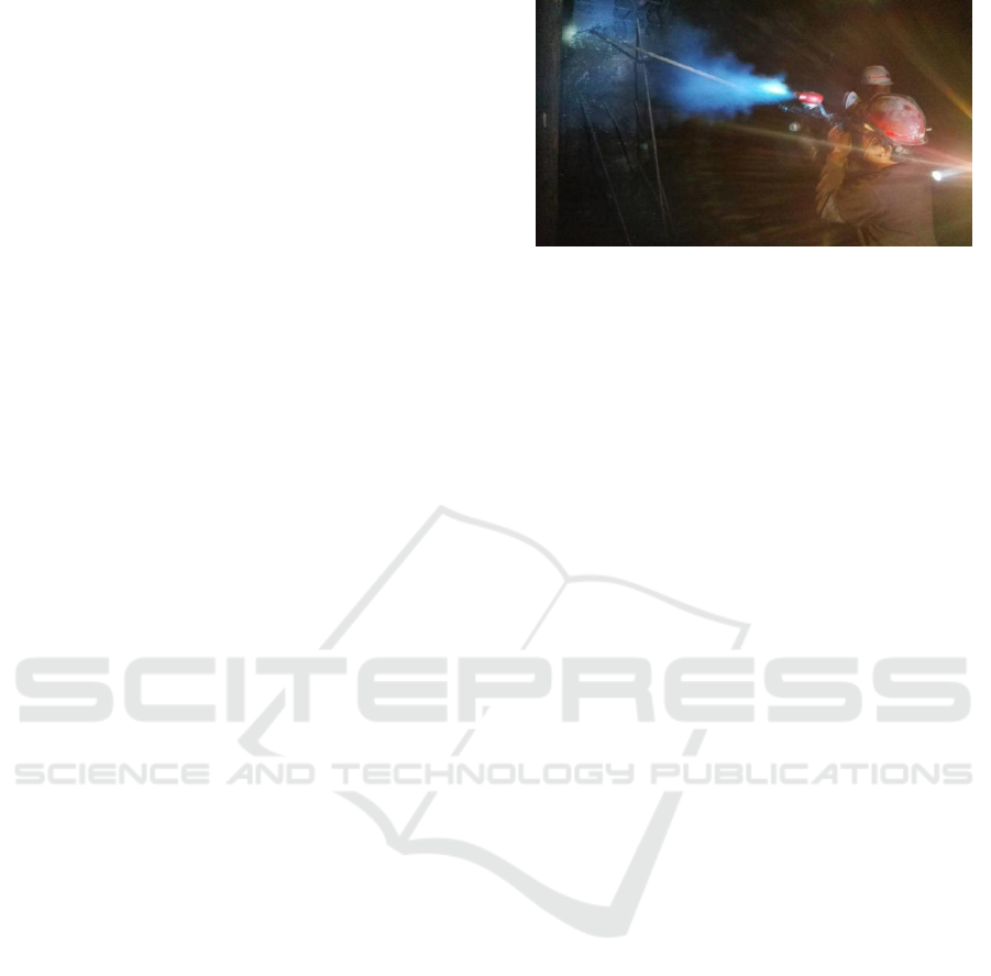
After the successful development of the above
two new mechanisms, they took the lead in the
application of S82 gas-leg rock drill. The first
prototype was tested in a metal mine (see Figure 3)
in Sichuan Province in 2017. The water pressure of
the mine is 0.2 MPa higher than that of the wind
pressure. The performance of the gas-leg rock drill
fully meets the design requirements, helping
customers to achieve rapid rock drilling, smooth
operation, shorter working hours, lower costs and
maximize the interests of customers. It is fully
recognized by customers.
Figure 3. Field tests.
REFERENCES
Cai Shumei. Lubrication mechanism for the head system
of a pneumatic rock drill [P]: China, 02243160.8.
2002-07-10.
Class B, Grade 75, Department of Foreign Languages,
Lanzhou University. Lubrication Theory and Practice
of Rock Drillers [J]. Pneumatic Tools for Rock
Drilling Machinery, 1979 (03), 27-34.
Liu Enguo. A Brief Analysis of the Development Trend of
Pneumatic Rock Drilling Machinery [J]. Pneumatic
Tools for Rock Drilling Machinery, Phase 4, 2013: 14-
16.
Liu Guangwen, Wang Yueyong, Liu Enguo. Research on
water washing mechanism of pneumatic rock drill [J].
Pneumatic tools for rock drilling machinery, No. 3,
2018: 37-39.
Liu Jian, Wang Yueyong. Lubrication and cooling
mechanism of a pneumatic rock drill [P]: China,
201520300855.6. 2015-05-12.
Luo Liangguang. Conception and Practice of New
Generation Energy-saving and Environmental-friendly
Rock Driller [J]. Pneumatic Tools for Rock Drilling
Machinery, 2008 (1), 4.
Translated by Chen Bingzhi. Durability of rock drilling
machinery and determination of accuracy of matching
parts [J]. Pneumatic tools for rock drilling machinery,
1987 (2), 47.
Yang Wansheng. Factors affecting the life of pneumatic
rock drills [J]. Pneumatic tools for rock drilling
machinery, Phase 2, 2008: 18-21.
ICVMEE 2019 - 5th International Conference on Vehicle, Mechanical and Electrical Engineering
174
