
Parametric Modeling and Hydrodynamic Analysis of Underwater
High Performance Propeller
Jixin Liu
1, a
, Tianhong Yan
1, b, *
, Bo He
2, c
, Hongbin Shen
1, d
and Jinliang Song
1, e
1
Department of Mechanical and Electrical Engineering, China Jiliang University, Hangzhou 310018, China.
2
Department of Information Science and Engineering, Ocean University of China, Qingdao 266100, China.
b)
Corresponding author email: thyan@163.com
c)
bhe@ouc.edu.cn
d)
shenhongbin94@163.com
e)
1195297498@qq.com
Keywords: Openprop, AUV, Propeller, Three-dimensional Modeling, Hydrodynamic Analysis, Thrust Test.
Abstract: At present, the propeller-dependent drive system is still the mainstream propulsion mode of underwater
vehicle. The propeller plays an important role in the whole propulsion system, and its effect directly affects
the thrust, speed, efficiency and endurance of the underwater vehicle. The propeller used by autonomous
underwater vehicle (AUV) should not only satisfy the demands of thrust and torque, but also high
efficiency. In this paper, four kinds of airfoil propellers with different sizes and shapes are designed based
on OpenProp software, and their performances are tested by thrust test. The comparison between the four
kinds of airfoil propeller and the contrast between the airfoil propeller and the MAU type four-bladed
propeller are made. In addition, a series of conclusions are drawn, which lays the foundation for designing
the propeller with high efficiency and thrust.
1 INTRODUCTION
Overview of underwater navigation equipment, both
large and small ships, yachts, lifeboats and various
underwater vehicles such as warships, submarines
are using propeller. Propeller propulsion is still one
of the most important way of propulsion. Although it
is not very efficient, but simple in structure and easy
to apply. With the progress of manufacturing
industry in China and the development of large-scale
machine tools and numerical control technology,
machining a propeller becomes more convenient.
The design parameters and machining accuracy of
propeller have a direct influence on the performance
of propeller, which in turn affects the movement of
underwater vehicle. Now the propeller machining
process is very simple. When the three-dimensional
software modeling is completed, model is imported
into the CNC machine tool. After simple
programming and tool setting, the machine tool
automatically completes the processing, and the
general accuracy can be guaranteed. Therefore, the
design parameters are really affecting the
performance of the propeller. The main parameters
includes paddle type, blade shape and quantity,
diameter, pitch ratio, disk ratio, longitudinal
inclination, propeller convolute and the diameter of
the rotor hub. When the propeller rotates, the side of
the cut water is the leading edge, and the other side
is the trailing edge. The surface of the blade pushing
the water is called the leaf surface, the other side is
called the leaf back. The leaf near the hub is the
blade root, and the outer side is the blade tip (X. F.
Xue, T. H. Yan, B. He, 2016). When the vehicle
travels forward, the propeller turns clockwise look
from the tail is right-rotor reverse propeller. When it
rotates counterclockwise, it is the left-rotor positive
propeller.
At present, the performance test method of the
propeller is mainly three-dimensional model open
water performance calculation (Z. Q. Yao, H. Gao,
C. L. Yang, 2008; L. Huang, L. Chen, 2014; W. G.
He, 2014; Y. W. Ding, J. M. Wu, Z. Q. Ma, 2018; X.
M. Wang, S. Feng, 2018; X. S. Xie, Z. F. Jiang, L.
Y. Qiu, 2015; J. M. Wu, Y. F. Lai, J. W. Li, 2016; F.
D. Gao, C. Y. Pan, 2011; C. Y. Liu, K. Luo, Q. Guo,
2017; T. Zhang, C. J. Yang, B. W. Song, 2011). The
advantages are low cost, save time and simple, but
144
Liu, J., Yan, T., He, B., Shen, H. and Song, J.
Parametric Modeling and Hydrodynamic Analysis of Underwater High Performance Propeller.
DOI: 10.5220/0008480601440154
In Proceedings of 5th International Conference on Vehicle, Mechanical and Electrical Engineering (ICVMEE 2019), pages 144-154
ISBN: 978-989-758-412-1
Copyright
c
2020 by SCITEPRESS – Science and Technology Publications, Lda. All rights reserved
the simulation results may not be accurate. Based on
OpenProp and SolidWorks, four kinds right-rotor
propellers used for AUV are designed. They are
processed into physicals to verify the design
parameters and propeller performance through thrust
test. The airfoil propeller and the map propeller are
compared, analyzed and summarized. Thrust test
both have advantage and disadvantage. The
advantage is that the result is accurate and reliable,
and the disadvantage is high cost and spend long
time.
2 THREE DIMENSIONAL
MODELING OF PROPELLER
The four propellers tested in this paper are suitable
for AUV. The AUV outer diameter is 324mm, total
length is 3800mm approximately and the mass is
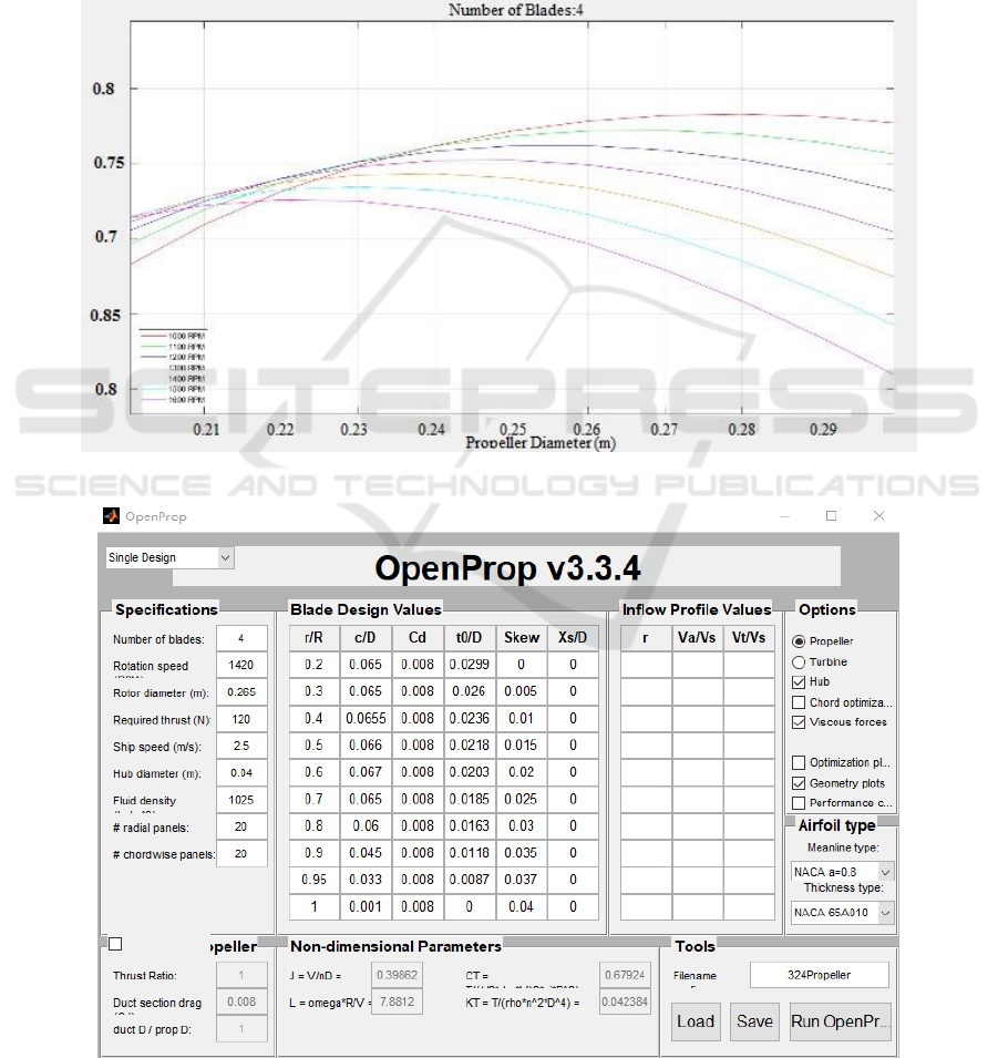
270kg in air. It is analyzed from the OpenProp
parameter research module that the big diameter of
the blade could improve the thrust and efficiency,
Figure 1. Parameter study curve.
Figure 2. Single design module parameters.
Parametric Modeling and Hydrodynamic Analysis of Underwater High Performance Propeller
145
but it can't exceed 85% of the outer diameter of the
AUV (R. S. Duelley, 2011). From the parameter
study curve as shown in Fig.1, the blade thickness
type is NACA 65A010 and the diameter is 210mm,
245mm, 265mm. There are three-bladed propeller
and four-bladed propeller. The rotation of them is
right-rotor, and the propeller hub diameter is 30mm
or 40mm.
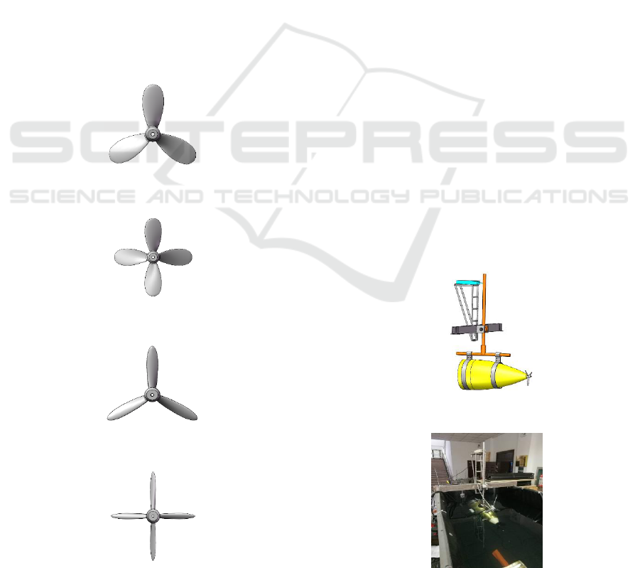
The silver narrow four-bladed propeller with a
diameter of 265 mm is taken as an example, and the
rest will not be described in this paper. First of all,
input the predetermined parameters in the single
design module of OpenProp as shown in Fig.2, and
run the program to generate the blade coordinate
points. Secondly, organize the data in three-
dimensional coordinate format to fulfill software’s
requirements, import the data into SolidWorks to
generate the blade, and design the hub through the
surface lofting and circumferential array (B. An, H.
H. Zhu, S. D. Fan, 2017; Y. F. Qin, X. J. Sun, X. H.
Lin, 2017). Then, add fillets at the root to increase
the intensity and generate the final three-
dimensional model as shown in Fig.3 to Fig.6.
Figure 3. Silver wide three -bladed propeller.
Figure 4. Silver wide four-bladed propeller.
Figure 5. Silver narrow three-bladed propeller.
Figure 6. Silver narrow four-bladed propeller.
3 THRUST TEST OF
PROPELLER
The experiment platform of this test is a thrust test
device as shown in Fig.7 and Fig.8. It is fixed on the
pool filled with seawater. The lever principle and the
equidistant force arm are used, and the lower arm is
connected to the AUV ankle propulsion system. The
upper arm is connected to the dynamometer. When
the propeller rotates to generate the thrust, the AUV
stern moves forward to drive the upper side to move
backwards. The thrust is transmitted 1:1 to the
dynamometer, and the thrust data can be read from
the dynamometer.
The thrust test is carried out in order from low
speed to high speed. The motor speed is changed
from 500 to 5000 rpm, for every 500 rpm increase.
The motor-to-propeller reduction ratio is 3.5. The
rated voltage of the motor to drive propeller is 48V,
and the peak current is set to 20A. Due to the low
manufacturing precision of the thrust test device and
the error of the underwater adjustment balance, the
data displayed by the tension meter has a jump when
the motor speed is below 1000 rpm. So the two
pieces of data recorded at the beginning have no
reference value. The test data is shown in Table 1
and Table 2. The black is a MAU type four-bladed
propeller with a diameter of 180 mm. The silver
wide four-bladed airfoil propeller has a diameter of
210 mm. The silver wide three-bladed airfoil
propeller also has a diameter of 210 mm. The silver
narrow four-bladed airfoil propeller diameter is
265mm, and the silver narrow three-bladed airfoil
propeller diameter is 245mm.
Figure 7. Three-dimensional drawing of thrust test device.
Figure 8. Physical drawing of thrust test device.
ICVMEE 2019 - 5th International Conference on Vehicle, Mechanical and Electrical Engineering
146

Table 1. Date of propeller thrust test one.
Motor
Rotating
Speed
(n)
Silver Wide Four-
bladed Propeller
(Reverse)
Silver Wide Three-
bladed Propeller
(Reverse)
Silver Narrow Four-
bladed Propeller
(Reverse)
Silver Narrow Three-
bladed Propeller
(Reverse)
Current
(A)
Thrust
(N)
Current
(A)
Thrust
(N)
Current
(A)
Thrust
(N)
Current
(A)
Thrust
(N)
500
1.2
16.5
0.7
10.2
0.95
7
1.1
21.1
1000
4
38.2
2.1
22
2.9
29.8
4.1
56.3
1500
9.5
86
4.8
46
5.9
65.2
8.2
104
2000
14.7
115
8.5
89
11.8
128
14
179
2500
—
—
12.5
120
13
148
—
—
3000
—
—
—
—
—
—
—
—
Table 2. Date of propeller thrust test two.
Motor
Rotating
Speed
(n)
Black Four-
bladed Propeller
(Correct)
Silver Wide
Four-bladed
Propeller
(Correct)
Silver Wide
Three-bladed
Propeller
(Correct)
Silver Narrow
Four-bladed
Propeller (Correct)
Silver Narrow
Three-bladed
Propeller
(Correct)
Current
(A)
Thrust
(N)
Current
(A)
Thrust
(N)
Current
(A)
Thrust
(N)
Current
(A)
Thrust
(N)
Current
(A)
Thrust
(N)
500
0.3
20
0.3
15
0.15
12
0.3
16
0.25
17
1000
0.65
22
1
17
0.35
14
0.55
18
0.85
19
1500
1.3
25
2.1
20
0.9
15
2
19
1.8
22
2000
2.65
28
4.1
25
1.7
16
3.3
20
3.3
25
2500
4
40
6
35
3.1
22
5.1
25
5.1
26
3000
5.7
55
9
55
4
28
6.5
32
8
44
3500
8.7
78
13
78
6.5
45
8.7
43
11
60
4000
10
93
20
100
8.5
60
11.5
55
13.5
74
4500
13.5
125
—
—
12
90
17.5
70
20
100
5000
18
145
—
—
14.5
95
19
80
—
—
In reference (J. M. Wu, L. Zhong, E. W. Zhang,
2017), the propeller thrust characteristics of the
underwater robot in reverse motion are studied. The
test shows that the propeller can generate a large
thrust at a lower speed after the reverse installation.
And the current is much smaller than the current
when the propeller is correct installation. However,
after the reverse installation, the phenomenon of
cavitation appeared. The phenomenon of cavitation
of the wide blade is more obvious than that of the
narrow blade. The influence of the cavitation factor
on the hydrodynamic characteristics of the propeller
blade is not only happened on the suction surface,
but also the pressure surface. There is a non-
negligible influence in reference (J. M. Wu, E. W.
Zhang, L. Zhong, 2018). According to the
relationship between the rotational speed and the
vacuole summarized in the reference (J. M. Wu, E.
W. Zhang, L. Zhong, 2018), further analysis and
improvement are needed to make the cavitation
phenomenon appear at high rotational speed,
avoiding the occurrence at low rotational speed.
4 DATA ANALYSIS AND
IMPROVEMENT
It can be clearly seen from Table 1 and Table 2 that
the performance of the four airfoil propellers is not
as good as the MAU type propeller tested in this
paper when in the correct installation, and the
performance in the reverse installation far exceeds
the MAU type propeller. Further, the efficiency of
each propeller is calculated from the data of the two
tables and the equations (1) to (3).
(1)
(2)
(3)
Parametric Modeling and Hydrodynamic Analysis of Underwater High Performance Propeller
147
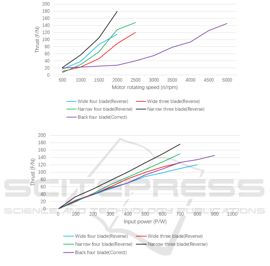
Figure 9. Relation curve between rotating speed and thrust.
Figure 10. Relation curve between input power and thrust.
In the formula, P1 is the input power. U is the
rated voltage of 48V. I is the current. P2 is the
output power. F is the thrust. P is the pitch ratio. D is
the propeller diameter. N is the propeller rotating
speed, the speed after deceleration of motor speed. η
is the efficiency of the propeller. When the propeller
is correct installation and motor speed at 4000 rpm,
the efficiency of the MAU type propeller is about
53%, and the efficiency of the four airfoil propellers
is between 40% and 46%. When the propeller
reverse installation and motor speed is 2000 rpm, the
efficiency of the silver narrow three-bladed propeller
and the silver narrow four-bladed propeller can
reach about 60%.
As shown in Fig.9 and Fig.10, the silver narrow
three-bladed propeller has the best performance
when it is reversed installation, and secondly the
silver narrow four-bladed propeller reversed
installation. In reference (R. S. Duelley, 2011), three
sets of chord/diameter parameters were studied
based on the lift line theory, and the efficiency
values of each group were compared as shown in
Table 3. Considering the performance, efficiency,
strength and ease of processing of the propeller, the
final design parameters are given in reference (R. S.
Duelley, 2011), as shown in Table 4.
ICVMEE 2019 - 5th International Conference on Vehicle, Mechanical and Electrical Engineering
148
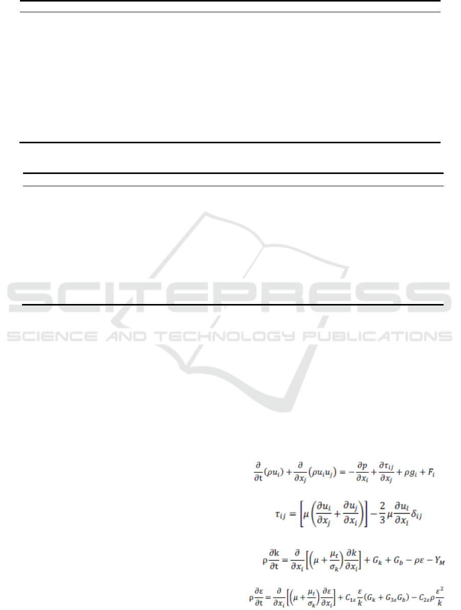
Table 3. Three sets of chord/diameter parameters.
r/R
C
1
/D
1
C
2
/D
2
C
3
/D
3
0.2
0.0800
0.0650
0.0530
0.3
0.0770
0.0770
0.0620
0.4
0.0730
0.0730
0.0650
0.5
0.0718
0.0718
0.0660
0.6
0.0680
0.0680
0.0670
0.7
0.0600
0.0600
0.0610
0.8
0.0500
0.0500
0.0500
0.9
0.0320
0.0320
0.0310
0.95
0.0200
0.0200
0.0200
1
0.0010
0.0010
0.0010
Efficiency
78.73%
78.74%
78.83%
Table 4. Final propeller geometry inputs.
r/R
t0/C
C/D
t0/D
Rake
0.2
0.4606
0.0650
0.0299
0
0.3
0.4001
0.0650
0.0260
0.005
0.4
0.3601
0.0655
0.0236
0.010
0.5
0.3302
0.0660
0.0218
0.015
0.6
0.3034
0.0670
0.0203
0.020
0.7
0.2841
0.0650
0.0185
0.025
0.8
0.2719
0.0600
0.0163
0.030
0.9
0.2632
0.0450
0.0118
0.035
0.95
0.2624
0.0330
0.0087
0.037
1
0.0000
0.0010
0.0000
0.040
According to the parameters of Table 4, the
narrow four-bladed propeller shown in Fig.6 was
designed. Through the thrust test and the actual
application test, although the ideal thrust was
generated, the autonomous underwater vehicle could
not achieve at a high speed under high efficiency.
The ratio of the chord/diameter of the above-
mentioned silver narrow three-bladed propeller is
about 1.7 times that of the narrow four-bladed
propeller. The optimized design of the silver narrow
three-bladed propeller is reduced to 210 mm in
diameter. The chord/diameter ratio is kept 1.7 times.
The thickness/diameter ratio is consistent with the
narrow four-blade, enabling it to achieve high
rotational speed while avoiding cavitation.
The optimized propeller is meshed by ICEM
CFD and imported into Fluent for hydrodynamic
performance simulation calculation (R. Muscari, G.
Dubbioso, M. Viviani, A. D. Mascio, 2017; W. H.
Lam, D. J. Robinso, G. A. Hamill, H. T. Johnston,
2012). The RNG k-epsilon turbulence model is
selected because this model is suitable for
calculating the rotational flow. Use MRF (A.
Bhattacharyya, V. Krasilnikov, S. Steen, 2016; S.
Sezen, A. Dogrul, C. Delen, S. Bal, 2018; M. M.
Helal, T. M. Ahmed, A. A. Banawan, M. A. Kotb,
2018) to calculate the flow problem of the rotating
domain. There are two domains, the flow domain
called Fluid and the rotating domain called Rotating,
and use the Interface to connect flow domain and
rotating domain. The simulation calculation is set as
the speed inlet, the pressure outlet. The inflow
velocity is 2.5 m/s. The propeller rotating speed is
1400 rpm. The simulation calculation (X. F. Xue, T.
H. Yan, B. He, 2016) is based on equations (4) to
(7):
(4)
(5)
(6)
(7)
Parametric Modeling and Hydrodynamic Analysis of Underwater High Performance Propeller
149
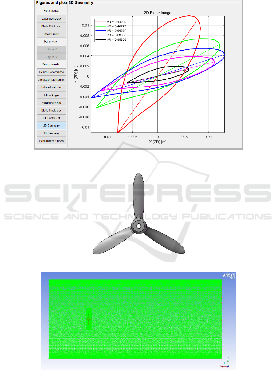
Figure 11. Optimized blade profile
Figure 12. Optimized narrow three-bladed propeller.
Figure 13. Mesh division of fluid and rotating domain.
ICVMEE 2019 - 5th International Conference on Vehicle, Mechanical and Electrical Engineering
150
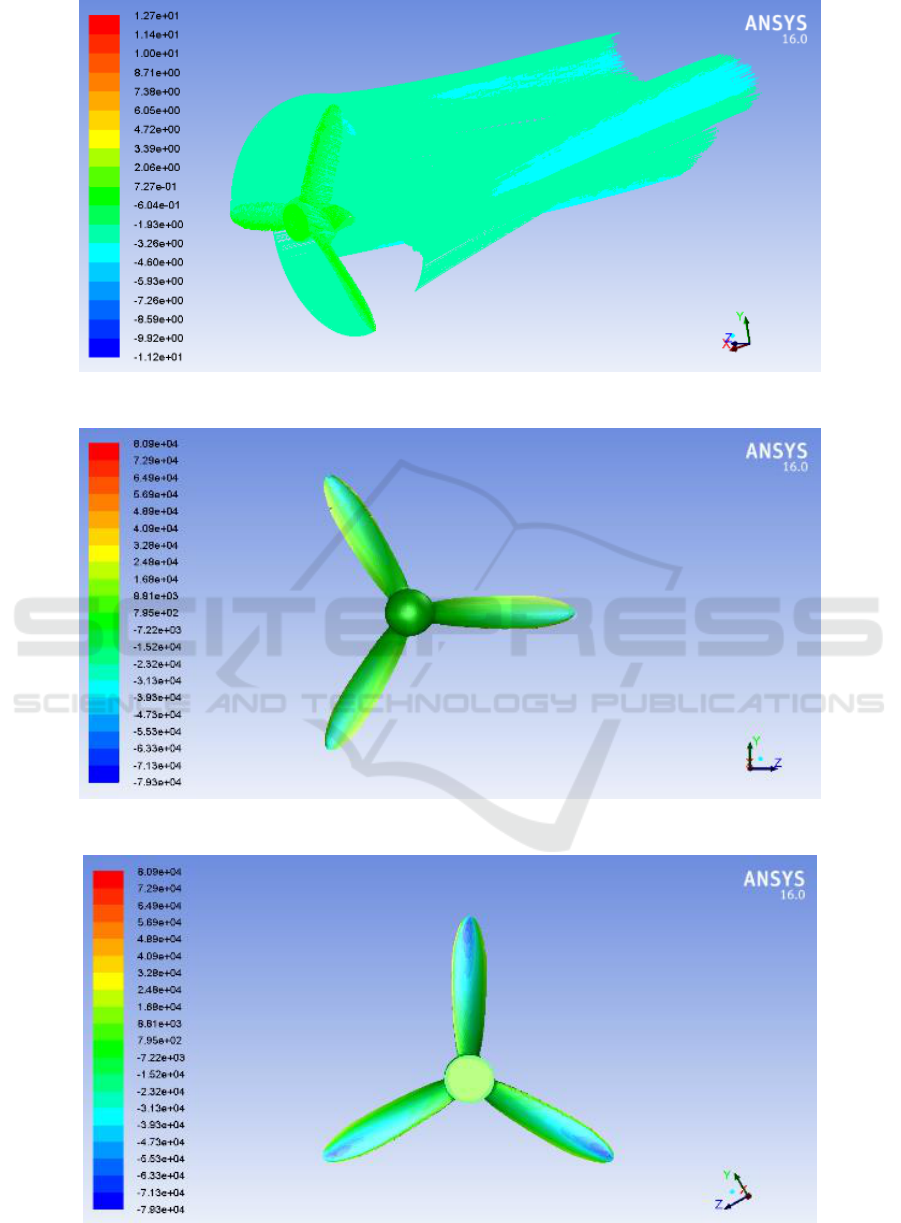
Figure 14. Axial velocity streamline diagram.
Figure 15. Propeller leaf pressure cloud map.
Figure 16. Propeller leaf back pressure cloud map.
Parametric Modeling and Hydrodynamic Analysis of Underwater High Performance Propeller
151
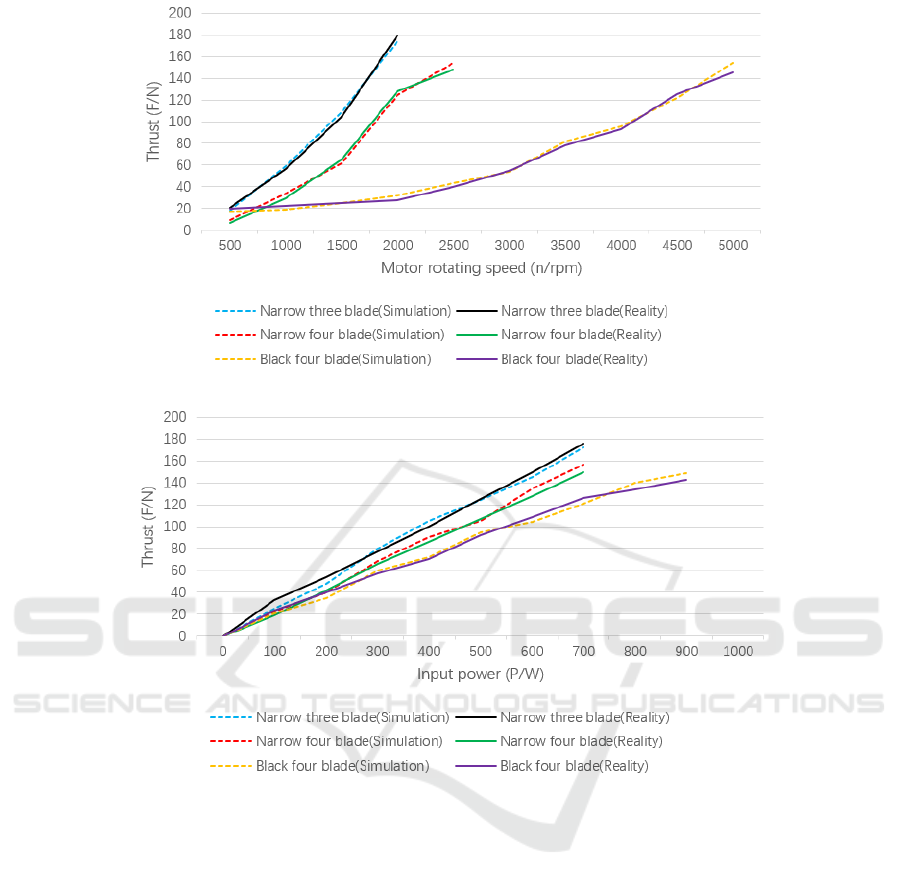
Figure 17. Relation curve between thrust and rotating speed.
Figure 18. Relation curve between thrust and input power.
In the formula, p is static pressure. τij is the
stress tensor. gi is the gravity volume force in the i
direction. Fi is the external volume force in the i
direction, Fi contains other model related source
terms. ui and uj are the mean value of the velocity
component in the xi and xj directions. ρ is the fluid
density. μ is the fluid viscosity coefficient. Gk is the
turbulent energy caused by the average velocity
gradient. Gb is the turbulent energy caused by
buoyancy. YM is influence of turbulent pulsation
expansion on total dissipation rate. μt is the turbulent
viscosity coefficient (X. F. Xue, T. H. Yan, B. He,
2016). The optimized propeller as shown in Fig.11
and Fig.12, and the mesh division and simulation
results. As shown in Fig.13 to Fig.16.
In this paper, the numerical simulation
calculation (N. Yilmaz, M. Atlar, M. Khorasanchi.,
2019; N. Abbas, N. Kornev, I. Shevchuk, P.
Anschau, 2015; D. Owen, Y. K. Demirel, E. Oguz,
T. Tezdogan, A. Incecik, 2018; A. Dubois, Z. Q.
Leong, H. D. Nguyen, J. R. Binns, 2019) uses speed
inlet and pressure outlet, which is the same as the
reference (Z. Q. Yao, H. Gao, C. L. Yang, 2008; W.
G. He, 2014; X. S. Xie, Z. F. Jiang, L. Y. Qiu, 2015;
J. M. Wu, Y. F. Lai, J. W. Li, 2016; F. D. Gao, C. Y.
Pan, 2011). The setting conditions are speed inlet
and free flow outlet in reference (H. P. Pei, R. Liu,
2018). Other setting conditions are similar. From the
simulation results, the propeller accelerates the rear
fluid. The water flows spirally through the propeller,
and the diameter of the rear flow field is smaller
than the diameter of the propeller. The fluid is dense
and smooth. The blade leaf of the propeller is
positive pressure, and the blade back leaf of the
propeller is negative pressure. The pressure
difference is large, indicating that the rotation of the
ICVMEE 2019 - 5th International Conference on Vehicle, Mechanical and Electrical Engineering
152

propeller produces a large thrust. The actual
application results are basically consistent with the
numerical simulation results, and the comparison
results are shown in Fig.17 and Fig.18. In summary,
the propeller has good hydrodynamic performance
and meets the needs.
5 CONCLUSIONS
According to the parameters of the reference (R. S.
Duelley, 2011), the propeller has not reached the
ideal efficiency value after the actual measurement.
In recent years, the research has not solved the
efficiency problem well. In this paper, the design
parameters are optimized based on the reference (R.
S. Duelley, 2011). The propeller produces a large
thrust while maintaining a high efficiency state.
Parametric modeling of propellers based on
OpenProp and SolidWorks, from theoretical analysis,
parameter research to data import and complete
three-dimensional modeling, saving a lot of time
spend on data calculation, making propeller design
and processing more convenient and faster. This test
verifies the reliability of this design method by
testing the actual application effect of the propeller
and comparing it with the theoretical design. The
test proves that the parametric modeling method by
using OpenProp are reliable. The results of the thrust
theoretical analysis are not much different from
those of the actual application.
This experiment tests the actual hydrodynamic
performance of the four propellers and draws the
following conclusions. Under the premise that other
parameters are consistent, the efficiency of the three-
bladed propeller is higher than the four-bladed
propeller. The efficiency of the narrow blade
propeller is higher than the wide blade propeller.
The efficiency of the small diameter propeller at
high rotating speed is greater than that at low
rotating speed. The efficiency of the large diameter
propeller at low rotating speed is greater than that at
high rotating speed. The change in back rake angle
has little effect on the hydrodynamic performance of
the propeller. For MAU type propeller tested in this
paper, the efficiency of correct installation and
reverse installation is very different. The correct
installation efficiency is much higher than the
reverse installation efficiency. However, the
efficiency of airfoil propeller correct or reverse
installation is not much different. And the
hydrodynamic performance in the reverse
installation is better than the MAU type propeller.
That is, the map propeller is suitable for single way
propulsion and the airfoil propeller is suitable for
double way propulsion.
ACKNOWLEDGEMENTS
This work was financially supported by the National
Key Research and Development Program of China
(Grant No. 2016YFC0301404) and the National
Natural Science Foundation of China (Grant No.
51379198).
REFERENCES
A. Bhattacharyya, V. Krasilnikov, S. Steen. A CFD-based
scaling approach for ducted propellers. Ocean
Engineering, 2016, 123, 116-130.
A. Dubois, Z. Q. Leong, H. D. Nguyen, J. R. Binns.
Uncertainty estimation of a CFD-methodology for the
performance analysis of a collective and cyclic pitch
propeller. Applied Ocean Research, 2019, 85, 73-87.
B. An, H. H. Zhu, S. D. Fan. Three-dimensional modeling
and performance analysis of an AU propeller. China
Ship Repair, 2017, 30(3), 48-52.
C. Y. Liu, K. Luo, Q. Guo. Performance prediction of
contra-rotating propellers for undersea vehicle.
Journal of Unmanned Undersea System, 2017, 25(5),
437-442.
D. Owen, Y. K. Demirel, E. Oguz, T. Tezdogan, A.
Incecik. Investigating the effect of biofouling on
propeller characteristics using CFD. Ocean
Engineering, 2018, 159, 505-516.
F. D. Gao, C. Y. Pan. Parameterized design and analysis
of the complicated curved-surface propeller in solid
modeling. Mechanical Science and Technology for
Aerospace Engineering, 2011, 30(1), 1-5.
H. P. Pei, R. Liu. Three-dimensional modeling and
hydrodynamic performance analysis of different pitch
angle propeller. Journal of Hangzhou Dianzi
University (Natural Sciences), 2018, 38(2), 78-83.
J. M. Wu, E. W. Zhang, L. Zhong. Thrust characteristics
of ducted propeller under the influence of cavitation.
Journal of South China University of Technology
(Natural Science Edition), 2018, 46(1), 41-49.
J. M. Wu, L. Zhong, E. W. Zhang. Simulation of
hydrodynamics of underwater robot in reverse
propeller and negative speed. Ship Engineering, 2017,
39(S1), 225-229,292.
J. M. Wu, Y. F. Lai, J. W. Li. Distribution characteristics
of thrust, advanced and induced velocity on ducted
propeller disk. Ship Engineering, 2016, 38(12), 23-26,
36.
L. Huang, L. Chen. Propeller modeling method and
open water performance study. Ship Electronic
Engineering, 2014, 34(8), 78-80.
M. M. Helal, T. M. Ahmed, A. A. Banawan, M. A. Kotb.
Numerical prediction of sheet cavitation on marine
Parametric Modeling and Hydrodynamic Analysis of Underwater High Performance Propeller
153

propellers using CFD simulation with transition-
sensitive turbulence model. Alexandria Engineering
Journal, 2018, 57, 3805-3815.
N. Abbas, N. Kornev, I. Shevchuk, P. Anschau. CFD
prediction of unsteady forces on marine propellers
caused by the wake nonuniformity and nonstationarity.
Ocean Engineering, 2015, 104, 659-672.
N. Yilmaz, M. Atlar, M. Khorasanchi. An improved Mesh
Adaption and Refinement approach to Cavitation
Simulation (MARCS) of propellers. Ocean
Engineering, 2019, 171, 139-150.
R. Muscari, G. Dubbioso, M. Viviani, A. D. Mascio.
Analysis of the asymmetric behavior of propeller–
rudder system of twin screw ships by CFD. Ocean
Engineering, 2017, 143, 269-281.
R. S. Duelley. Autonomous underwater vehicle propulsion
design. Master Thesis, Virginia Polytechnic Institute
and State University, Blacksburg, 2011, pp.78.
S. Sezen, A. Dogrul, C. Delen, S. Bal. Investigation of
self-propulsion of DARPA Suboff by RANS method.
Ocean Engineering, 2018, 150, 258-271.
T. Zhang, C. J. Yang, B. W. Song. CFD simulation of the
unsteady performance of contra-rotating propellers.
Journal of Ship Mechanics, 2011, 15(6), 605-615.
W. G. He. Simulation calculation and analysis of vessel
propeller’s open water performance. Ship Engineering,
2014, 36(S1), 48-51.
W. H. Lam, D. J. Robinso, G. A. Hamill, H. T. Johnston.
An effective method for comparing the turbulence
intensity from LDA measurements and CFD
predictions within a ship propeller jet. Ocean
Engineering, 2012, 52, 105-124.
X. F. Xue, T. H. Yan, B. He. Modeling and hydrodynamic
performance analysis of MAU propeller. Ship
Engineering, 2016, 38(1), 38-42.
X. M. Wang, S. Feng. Simulation and analysis of
hydrodynamic performance of propeller of small ROV.
Ship Engineering, 2018, 40(S1), 321-324,345.
X. S. Xie, Z. F. Jiang, L. Y. Qiu. Study on propeller
unsteady performance in viscous non-uniform wake.
Ship Engineering, 2015, 37(6), 37-40, 62.
Y. F. Qin, X. J. Sun, X. H. Lin. Propulsive efficiency of
low rotation propeller for underwater glider. Journal
of PLA University of Science and Technology (Natural
Science Edition), 2017, 18(1), 61-67.
Y. W. Ding, J. M. Wu, Z. Q. Ma. Analysis of thrust
characteristics of ducted propeller based on lattice
boltzmann method. Ship Engineering, 2018, 40(S1),
104-109.
Z. Q. Yao, H. Gao, C. L. Yang. 3D modeling and
numerical analysis for hydrodynamic force of
propeller. Ship Engineering, 2008, 30(6), 23-26.
ICVMEE 2019 - 5th International Conference on Vehicle, Mechanical and Electrical Engineering
154
