
Study on Intermittent Failure Phenomenon of the Automotive
Environmental Light Sensor
Guangming Li
1, 2, a, *
, Wenhua Yuan
1, 2
, Jun Fu
1, 2
and Yi Ma
1, 2
1
Department of Mechanical and Energy Engineering, Shaoyang University, Shaoyang 422000, China
2
Key Laboratory of Hunan Province for Efficient Power System and Intelligent Manufacturing, Shaoyang University,
Shaoyang 422000,China
Keywords: Cars, Environmental light sensor, Intermittent, Failure, Tide, seal.
Abstract: According to the failure or intermittent failure of the FC-3AB ambient light sensor that feedback from the
production site of Geely Automobile, the vehicles in this condition were tested and it is found that after the
key hits the ignition lock ON file and switch the AUTO file, ark light environment (palm cover sun sensor)
lights automatically open function is failure. When the car headlight is turned on manually, the headlight
can be turned on, indicating that there is no problem with the car headlight. In this paper, the factors that
cause the failure are collated and analyzed, and the fish bone map is drawn. Through the analysis of the
quality of the ambient light sensor and the analysis of the process steps, it is determined that the solution is
to seal the sensor assembly to ensure that the internal circuit of the shell does not fail due to moisture, the
headlights of the car can be turned on normally, and the light in the car can be automatically adjusted.
Eventually, the correctness of the solution is verified through experiments, and the failure rate of the
automotive ambient light sensor is minimized, effectively improving the reliability of the ambient light
sensor and the safety of driving.
1 INTRODUCTION
With the rapid development of power electronics
technology, electrical control systems are
increasingly integrated (Wu gang, wang xiaoyu,
zhang Yang, liu jia, 2015) Among them, the safety
fault of automobile ambient light sensor is directly
related to the safety of driving and can not be
ignored. The failure or intermittent failure of the
ambient light sensor will prevent the car headlights
from turning on automatically, resulting in a greater
probability of accidents in traffic when a tunnel or
dark light section is encountered, which will
seriously affect the safety of the occupants. At the
same time, it also poses a threat to facilities outside
the car and pedestrians or other vehicles (Zhang
deqian, hong yuanquan, zhao yongquan, 2017)
And ... According to statistics, about 5,000 traffic
accidents are caused by driving fatigue during
driving each year, of which about 400 directly cause
death, and the situation in Europe is roughly the
same. In June 2017, there were 63 failures or
intermittent failures of the FC-3AB ambient light
sensors that were feedback from the production site
of the Xiangtan Geely Automobile Assembly
Workshop. The phenomenon was that the vehicle
was charged (the key hit the ignition lock ON file) +
after switching the AUTO file. Dark light
environment (Palm cover sun sensor) lights
automatically open function failure. In this paper,
the failure rate of vehicle ambient light sensor is
minimized and the reliability of ambient light sensor
is improved.
2 ANALYSIS ON THE CAUSES
OF FAILURE OF
ENVIRONMENTAL LIGHT
SENSOR
2.1 Environmental Light Sensor
Voltage Testing
After testing, the input level V2 of the normal part is
less than the output level V3 under dark light
condition, and the headlamp can be turned on
10
Li, G., Yuan, W., Fu, J. and Ma, Y.
Study on Intermittent Failure Phenomenon of the Automotive Environmental Light Sensor.
DOI: 10.5220/0008387400100014
In Proceedings of 5th International Conference on Vehicle, Mechanical and Electrical Engineering (ICVMEE 2019), pages 10-14
ISBN: 978-989-758-412-1
Copyright
c
2020 by SCITEPRESS – Science and Technology Publications, Lda. All rights reserved

normally; under dark light condition, the input level
V2 is larger than the output level V3, and the
headlamp is not on. By testing the voltage of the
circuit, it can be determined that there is a quality
problem with the ambient light sensor assembly.
Voltage test values are shown in table 1 and table 2.
Table 1. Test results for normal parts.
Coding
Input
Voltage
V2(V)
Output
Voltage
V3(V)
Ispection
Results
1
373
125
qualified
2
396
142
qualified
3
367
119
qualified
4
402
183
qualified
5
421
166
qualified
6
385
152
qualified
7
397
169
qualified
8
372
143
qualified
Table 2. Test results for failure pieces.
Coding
Input
Voltage
V2(V)
Output
Voltage
V3(V)
Ispection
Results
1
298
672
unqualified
2
421
683
unqualified
3
361
1220
unqualified
4
200
872
unqualified
5
375
872
unqualified
6
321
962
unqualified
7
298
738
unqualified
8
342
697
unqualified
2.2 Photodiode Fault Troubleshooting
The photoelectric sensor fault screening, the most
important is whether the screening is photodiode
whether there is a quality problem, so the
photodiode also to carry out voltage testing. The test
of photodiode is also to verify the relationship
between input voltage and output voltage. As is
known to all, photodiode has one-way conductivity,
and if the photodiode is reversed, the resistance will
become infinite. The corresponding voltage will also
change, and this test is based on this principle to
verify whether the photodiode is qualified or not.
As shown in table 3 and table 4, the photocell
ratio of the two groups of components is basically
the same, and it can be seen from the voltage test
that they have one-way conductivity, which proves
that there is no fault of the two groups of
photodiodes, so the fault of the photodiode itself is
eliminated.
Table 3. Photodiode voltage test results for normal
components.
Coding
Input
Voltage
V2(V) (V)
Output
Voltage
V3(V)
Ispection
Results
1
19.26
1
qualified
2
19.14
1
qualified
3
19.24
1
qualified
4
19.07
1
qualified
5
19.33
1
qualified
6
19.12
1
qualified
7
19.27
1
qualified
8
19.36
1
qualified
Table 4. Photodiode voltage test results for fault
components.
Coding
Input Voltage
V2(V)(V)
Output
Voltage
V3(V)
Ispection
Results
1
19.27
1
unqualified
2
19.36
1
unqualified
3
19.14
1
unqualified
4
19.36
1
unqualified
5
19.33
1
unqualified
6
19.17
1
unqualified
7
19.07
1
unqualified
8
19.32
1
unqualified
Study on Intermittent Failure Phenomenon of the Automotive Environmental Light Sensor
11

2.3 Red Rubber Reflow Soldering Step
Checking
The so-called reflow soldering is to melt the solder
paste (solder paste) so that the surface-assembled
components and PCB boards are firmly bonded
together (Qi cheng, 2011). The equipment used is a
reflow soldering furnace located behind the mounter
in the production line. For example, table 5 is the
reference temperature of common red adhesive
reflow welding process, and the reference
temperature of three kinds of solder paste commonly
used in the table is at different temperature zones.
Table 6 is the equipment parameters of the
manufacturer. The solder paste used is SN63PB37.
You can see, the equipment parameters and
reference parameters are consistent basically,
because considering the time cost, this will be a
thing or two, three or four low temperature region
merging, and slightly increased the welding
temperature, but these smaller factor changes will
not affect the process to produce waste, therefore
rule out the possibility that this process has a
problem.
In addition, it is necessary to consider whether
the quality of the patch is affecting the overall effect
of the photoelectric sensor. So first check the patch
model, found no error. After the replacement of the
normal pieces of the patch, the products are OK.
Then check whether the patch position of the fault
parts is correct, and find that there is no part beyond
the welding pad at both ends, so there is no problem
with the patch. Therefore, there is no problem with
the process.
Table 5. Three solder paste reflow soldering temperature
Settings at 8 temperature zone.
Temperatur
e Range
SN63PB3
7
SN42BI5
8
SN96.CU
O
1
130°C
80°C
130°C
2
140°C
110°C
160°C
3
150°C
130°C
180°C
4
160°C
150°C
200°C
5
175°C
160°C
220°C
6
190°C
180°C
240°C
7
210°C
190°C
255°C
8
200°C
180°C
235°C
Table 6. Equipment parameters of manufacturers
1,2
3,4
5
6
7
8
140°C
170°C
190°C
200°C
220
190
2.4 Wave Crest Welding Procedure
Inspection
First consider whether the parameters for this
process are set correctly. First, consider preheating.
The tin furnace temperature of this process is kept at
250°C , which is consistent with the reference value.
Therefore, there is no problem with the process.
Then consider the transport speed (stripping speed).
Generally speaking, too fast stripping speed will
lead to PCB preheating not reaching the ideal
temperature, and too slow will lead to too high
temperature, which may damage PCB board.
Therefore, the speed is usually set at 1100mm-
1200mm, which is consistent with the
manufacturer's production parameters. Finally, the
quality of flux was considered. The flux model was
RF800, and the manufacturer was found to have the
production qualification, so there was no problem
with the model. However, it was observed that the
surface of the fault parts could help with flux
residue, and it was considered that poor contact of
the circuit was caused by flux residue. Therefore, the
surface of the fault parts was cleaned with washing
board water, and then assembled and tested. It was
found that the product could work normally, so we
considered that the intermittent failure of the
ambient light sensor was caused by the quality of
flux. In order to further confirm this idea, we applied
for trial production of 500 pieces of GOLF nh-4 flux
and put them into the refrigerator for moisture
regain. The final test results showed that no such
phenomenon occurred in all products. Therefore, it
can be concluded that the quality of flux causes
intermittent failure of ambient light sensor.
2.5 Wire Harness Welding Inspection
No broken skin or core leakage was found in the
wiring harness inspection. Therefore, the quality
problem of the two hardware is excluded. The
welding method is manual welding, and the
temperature is 350°C, which conforms to the
specified temperature.
Based on the above tests, it can be concluded that
the intermittent failure of ambient light sensor is
caused by short circuit due to poor flux quality. In
order to verify that the fundamental factor is the
quality of flux, make the following test again: clean
the flux residue of the failed parts with washing
board water, and then dry the test, and find that
100% of the failed parts can be used normally. Then
a control group was made again. Another part of the
defective parts were cleaned with plate washing
ICVMEE 2019 - 5th International Conference on Vehicle, Mechanical and Electrical Engineering
12
water and then dried naturally. Then they were put
into the refrigerator for moisture regain for two
hours. It is concluded that the flux residue absorbs a
certain amount of moisture and leads to short circuit.
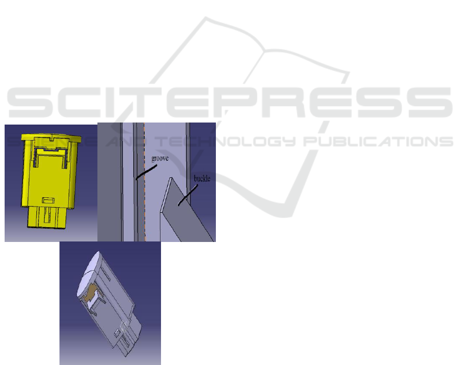
3 IMPROVED DESIGN
As shown in Fig.1 (a), there is no gap in the buckle
part of the shell to prevent the water vapor from
entering, but the buckle cannot be recessed when
under pressure, so the sensor assembly cannot be
easily installed in the car. If a large pressure
assembly is used, it may crack the sensor housing
and cause water vapor to enter. It is planned to set an
impervious groove in the location of the buckle.
Before drawing the groove, the dimensions of the
buckle and the shell should be analyzed. In the
modeling process of the original part mentioned
above, the shell thickness is defined as 1.05mm, and
the buckle height is 3.6mm. Suppose the groove
depth is defined as 1.0mm, the sensor assembly
moves the distance of the buckle to the inside when
assembling, which is 1.0mm, making it difficult to
assemble. Therefore, to increase the depth of the
groove, the inner wall of the shell should be
thickened. The improved design is shown in Fig.1 (b)
and Fig.1 (c).
(a) Fault component model, (b) The design of the grooves,
(c) Improved model
Figure 1. Comparison of models before and after
improvement.
Because the size of the base is designed
according to the outline of the bottom of the shell,
there will not be too large gaps in the assembly.
Sealing performance, in order to guarantee the
assembly requirements shell and base are assembled
on the base of the surface coated with sealant, if
adopts the integration of welding seal due to the
welding quality is not controllable, can cause there is
not roa (Zhang cao, 2008), and the price of this
product is very low ambient light sensor, when the
sensor in the cause of the problem, only need to
replace the sensor, so apply sealant is appropriate.
4 IMPROVE THE
EXPERIMENTAL
VERIFICATION OF THE
DESIGN SCHEME
Considering the contingency of failure, 300 pieces
of environmental light sensor with improved design
were trial-produced, and the test results were 100%
qualified rate, and the voltage was V2 less than V3.
Therefore, the possibility of deviation of
experimental results caused by product quality
problems is excluded.
Although the sealing technology is not a leading
technology, it is often a decisive key technology
(Chen feng, zhang wei, wang xunming, 2011). The
sealing technology in this paper is related to the
safety and reliability of vehicles, so it is necessary to
conduct an extreme environment test for the
inspection link. Check the sealing performance of
the product, put the product in the refrigerator for
moisture regain, so as to expose the product to the
air with the relative humidity of 100%, and simulate
the air environment with extreme humidity as much
as possible. In order to verify that the product can be
used reliably in a humid environment for a long
time, the moisture return time is specially set as 3
days. After the return of moisture, the voltage of the
ambient light sensor was tested, and it was found
that 100% of the input voltage of the product was
lower than the output voltage, and the voltage was
normal. The product is then assembled into the
vehicle, and the headlights can be started and opened
in the case of dark light. Cover the sensor with your
palm, and the headlights can be automatically
opened without failure.
Study on Intermittent Failure Phenomenon of the Automotive Environmental Light Sensor
13

5 CONCLUSION
Based on the ambient light sensor failure
phenomenon appears in the car caused headlight,
opening and closing failure first detect the quality of
optical sensor, found the photodiode itself there is no
quality problem, second to the ambient light sensor
process troubleshooting steps, mainly check the
reflow, wave soldering process, and found in wave
soldering, flux residues led to the sensor failure, the
last light sensor wiring harness for testing, test is
normal, thus determine only flux residues led to the
failure in the product. The failure reason is that the
flux is affected by moisture and water absorption,
resulting in short circuit of the circuit board.
According to the failure reason, the improvement
plan is to seal the shell, mainly to improve the size
and position of the shell and base buckle. Define
grooves to ensure that the buckle can move inward
under pressure and ensure the sealing of the shell; In
order to ensure no gap between the base and the
shell, interference fit is adopted. The rationality of
the improved design is verified by the sealing and
reliability test of the new product.
ACKNOWLEDGMENTS
Fund projects: outstanding youth project of
education department of hunan province (16B235),
general scientific research project of education
department of hunan province (17C1444 and
16C1432), and CX2016SY015 of postgraduate
scientific research innovation project of shaoyang
university.
About the author: li guangming (1983-), male,
born in shaoyang, hunan province, master degree,
mainly engaged in vehicle engineering teaching and
research of automobile testing technology.
REFERENCES
Chen feng, zhang wei, wang xunming. Design and
application of seal for super-large flow LNG pump [J].
Mechanical design and manufacturing, 2011 (05):74-
76.
Qi cheng. SMT process key points and defect treatment [J].
Printed circuit information, 2011 (08):62-67.
Wu gang, wang xiaoyu, zhang Yang, liu jia. Electrical
control system of ball mill based on PLC and sensor
technology [J]. Coal mine machinery, 2015,
36(10):281-283.
Zhang cao. Discussion on the sealing structure of multi-
cavity profile type flow detector [J]. Coal mine
machinery, 2008, 39 (10):74-76.
Zhang deqian, hong yuanquan, zhao yongquan.
Application of environmental light sensor TSL2581 in
highway tunnel lighting control [J]. Experimental
technology and management, 2017, 34 (10):78-81.
ICVMEE 2019 - 5th International Conference on Vehicle, Mechanical and Electrical Engineering
14
