
Power Supply Meshes based Line Routing for Urban MV
Distribution Network Planning
Ning Luo
1, a
, Hua Gao
1, b
, Zhuding Wang
2, c
, Molin He
1, d
1
Power grid planning research centre of Guizhou Power Grid Co., Ltd,Chongqing, 550000, China
2
State Key Laboratory of Power Transmission Equipment & System Security and New Technology, Chongqing University,
Chongqing 400044, China
Keywords: MV line routing planning, power supply mesh, shortest path algorithm, two-step algorithm, trunk line.
Abstract: Considering that it is difficult to determine the load points or the locations of user access facilities in urban
areas for the planning years, an optimization method for the routing planning of urban medium - voltage
(MV) trunk lines is proposed based on power supply meshes. Firstly, based on the results of load forecasting
and high voltage substation planning, power supply meshes are generated in the entire planning area
according to the principle of selecting standby substations close to loads. Then, based on the thinking line of
“trunk firstly, branch then”, a shortest path based two-step algorithm is proposed to find the shortest trunk
lines for the load centres of power supply meshes and the shortest trunk tie-line be-tween the load centres of
each mesh. A numerical example shows that the method is practical and feasible, which can provide a
reference for the reasonable routing scheme of medium voltage trunk lines.
1 INTRODUCTION
At present, most of the medium-voltage line routing
planning methods need to know the layout of load
points or the locations of user access facilities (such
as distribution transformers, switching stations or
ring network units) for the planning years (
Song
Meng, Liu Jian, Liu Gongquan, 2005; LI You, CHANG
Xianrong, 2013; LU Zhi-ying, TIAN Shuo, CHENG
Liang, et al, 2014; GE Shaoyun, WU Qing, et al, 2005;
Koutsoukis N C , Georgilakis P S, 2017
). Those
methods may be suitable for the rural distribution
network planning, but are not effective enough for
the urban distribution network planning because of
the difficulty in determining the locations of user
access facilities for the planning years. In recent
years, the power supply meshes based MV
distribution network planning has been carried out
successively in power grid enterprises (
Ming Xu,
Wang Zhuding, Wang Jingyu, etc, 2018; Wang Jingyu,
Wang Zhuding, Zhang Yongbin, et.al, 2018; Gu yuan,
2018)
. For the large-scale MV distribution net-work
planning, the main purpose of power supply meshes
based planning is to transform the large-scale
complex network planning of whole planning area
into relatively simple and independent network
planning for much smaller power supply meshes
with the mesh generation being satisfying the
technically feasible and economically optimal
principle for the whole network planning.
In this paper, the power supply meshes are firstly
generated in the entire planning area according to
the principle of selecting standby substations near
loads, and then based on the thinking line of “trunk
firstly, branch then”, a shortest path based two-step
algorithm is proposed for MV line routing planning
to find the shortest power supply trunk lines for the
load centres of power supply meshes and the
shortest trunk tie-line between the load centres of
each mesh. It is shown through a numerical example
that the thinking line and method presented in this
paper are of great practical value for MV line
routing planning.
2 MESH OPTIMIZATION
GENERATION
In this paper, a mesh is defined as the moderately
sized area supplied by the two substations (i.e., the
main supply one and standby one). Based on the
layout of main channels, the standby substations
310
Luo, N., Gao, H., Wang, Z. and He, M.
Power Supply Meshes based Line Routing for Urban MV Distribution Network Planning.
DOI: 10.5220/0008386403100316
In Proceedings of 5th International Conference on Vehicle, Mechanical and Electrical Engineering (ICVMEE 2019), pages 310-316
ISBN: 978-989-758-412-1
Copyright
c
2020 by SCITEPRESS – Science and Technology Publications, Lda. All rights reserved
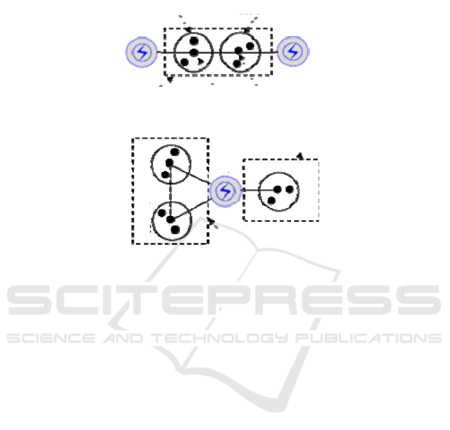
(a) inter-substation mesh
Inter-substation mesh
Load A1 Load B1
Substation A Substation B
Power supply area A1
Power supply area B1
(b) intra-substation mesh or radiation mesh
intra-substation mesh
radiation mesh
Power supply
area A3
Power supply
area A1
Power supply
area A2
Substation
A
Figure 1. Diagrams of tie-line mode based mesh classification.
close to loads are selected in the whole planning
area, resulting in the optimized meshes. The specific
steps of mesh optimization generation are as follows
(
Ming Xu, Wang Zhuding, Wang Jingyu, etc, 2018):
(1) Determining the main supply substation for
each load
Firstly, the power supply area of each substation
is obtained according to the substation optimization
planning (
Wang Yujin, 2011; HUO Kailong, WANG
Zhuding, ZHANG Daihong, et al, 2017)
, and then each
substation is called the main supply substation of the
loads in its power supply area. Taking the simplified
system shown in Fig.1 (a) as an example, if loads A1
and B1 respectively are located in the power supply
areas of substations A and B, the main supply
substations of loads A1 and B1 are respectively
substation A and substation B.
(2) Determining the standby substation for each
load
Based on the layout of main channels and an
allowable power supply radius, the possible standby
substation close to a load is found. Taking Fig.1 (a)
as an example, the standby substations of loads A1
and B1 are respectively identified as substation B
and substation A because they are closest to loads
A1 and B1 except for the loads’ main supply ones.
(3) Generating inter-substation meshes
In this paper, the inter-substation mesh is defined
as the area whose power supply substations can be
transferred between two substations. The inter-
substation mesh generation method is to firstly d
classify the loads of the same main supply substation
and the same standby substation into one supply
area, and to then merge the two supply areas with
opposite main and standby substations into one
inter-substation mesh.
Taking Fig.1 (a) as an example, the main and
standby substations of all loads (e.g. load A1) in
supply area A1 are respectively substation A and
substation B, and the main and standby substations
of all loads (e.g. load B1) in supply area B1 are
respectively substation B and substation A. Since the
main and standby substations of supply area A1 and
supply area B1 are opposite, they can be merged into
an inter-substation mesh involving substations A and
B.
(4) Generating intra-substation meshes and
radiation meshes
In this paper, an intra-substation mesh is defined
as the power supply area whose supply feeders can
be transferred between the different feeders from the
same substation, and a radiation mesh is defined as
the power supply area with no standby supply
substation or tie-line.
Power Supply Meshes based Line Routing for Urban MV Distribution Network Planning
311

For the loads which cannot be classified into
inter-substation meshes and are within the power
supply area of a certain substation, they are
classified into moderately sized areas based on
expert experience or a load clustering method. Then,
according to actual demand and the principle of
selecting standby feeders close to load centres, the
intra-substation meshes or radiation meshes are
generated with the main channel layout and the
power supply radius being satisfied, as shown in Fig.
1 (b).
(5) Manual intervention
Other issues of a power supply mesh may
include clear physical geography and management
boundaries, the same or close load classification
levels, the same power supply reliability
requirement, and the approximate same load sizes of
supply areas. Planners need to use their experience
to first analyse and then further adjust a mesh
generation scheme through manual intervention.
3 NETWORK MODEL
Based on an urban road network, the network model
of candidate channels for line routing and
corresponding network node types are defined.
3.1 Channel Network
With an urban road network being regarded as the
candidate channels for line routing, a channel
network can be represented by the weighted
undirected graph
,,
g
ggg
GVEW
()
, where
12
, ...
g
gg gn
VVVV()
and
g
E
respectively represent channel
nodes and the set of edges between channel nodes
(i.e., the segments of candidate channels),
g
W
is the
set of comprehensive costs for the corresponding
edges in
g
E
.
As in (
WANG Zhuding, QIU Jun, 2002), all
network edges (or segments) can be divided into two
subsets: 1) branches and 2) links. The branches are
the edges constituting the graph tree of network
along with the nodes, and the other network edges
are the links.
3.2 Node Classification
Channel network nodes are geographically divided
into three types: high voltage substation nodes, load
centre nodes and common nodes. In Fig.2, node #51
is a substation node, and node #26 is a load centre
node.
4 OPTIMIZATION MODEL OF
TRUNK LINE ROUTING
4.1 Optimization Model
For each of relatively independent meshes, the
optimization planning of trunk line routing is carried
out with the objective of minimizing the overall cost
of trunk lines with the connectivity of trunk line
channels being satisfied and the supply areas’ load
centres being passed through by trunk line channels
(hereafter abbreviated as a load centre constraint).
The corresponding routing optimization model can
be expressed as follows.
,
,g,
MV ,
MV ,
min , 1, ,
()1
..
()1
gi
g
ib m
bE
gi
gi
f
CiN
E
st
E
…
(1)
Where,
m
N
is the total number of all power
supply meshes,
,gi
E
is the set of channel segments
(or edges) for the trunk line in mesh i,
,gb
C
is the
comprehensive line cost of channel segment (edge)
i,
MV ,
()
gi
E
and
MV ,
()
gi
E
are respectively the
judgment functions of load centre constraint and
connectivity of trunk line channels corresponding to
,gi
E
(Being equal to 1 represents that the load centre
constraint or the connectivity is satisfied).
4.2 Determining of Load Centres
Let the coordinates of load point j in power supply
area i be (xj, yj). Considering that a load moment
(i.e., a load power multiplied by the distance
between the load and its supply substation) is
approximately proportional to the corresponding
voltage loss, investment and operation cost, the
selection of load centre position (xA,i, yA,i) for
supply area i should minimize the sum of all load
moments for the load points within power supply
area i,. Thus, we have
ICVMEE 2019 - 5th International Conference on Vehicle, Mechanical and Electrical Engineering
312
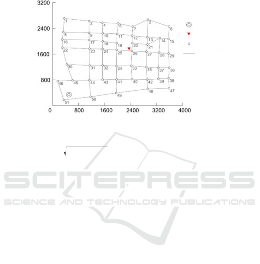
Abscissa of channel nodes / m
Ordinate of channel nodes / m
substation site
load center
channel nodes
candidate
channel path
Figure 2. Diagram of node classification.
,,
22
,,,
min - -
LP i LP i
Ai j j Ai Aiij
jS
j
j
j
S
fL xyyPxP
(2)
Where
j
P
is the active power of load point j,
,
L
Pi
S
is the set of all load points within power supply
area i,
,ij
L
is the distance between the load centre of
supply area i and load point j.
Let
,,
/0
Ai Ai
df dx
and
,,
/0
Ai Ai
df dy
, the load
centre coordinates of power supply area i can be
given by
,
,
,
,
,
,
/
/
/
/
LP i
LP i
LP i
LP i
jj ij
jS
Ai
jij
jS
jj ij
jS
Ai
jij
jS
Px
x
P
Py
y
P
L
L
L
L
()
,
()
()
()
(3)
Given the initial load centre location of a power
supply area, the final load centre location can be
obtained iteratively by an alternating method of
location and power allocation (
Wang Yujin, 2011).
5 SHORTEST PATH BASED TWO-
STEP ALGORITHM
If the load centres of supply areas are known, based
on the shortest path algorithm (
Gong Qu, 2009), the
routing of trunk lines from the load centres to their
main supply substations is performed firstly, and
then the routing of the trunk lines between the two
load centres in a mesh is carried out.
(1) Routing from a load centre to its main supply
substation
Firstly, a virtual node is created and the
comprehensive costs between the virtual node and
all main supply substations are assumed to be zero,
while the comprehensive costs between the virtual
node and the other channel network nodes are
assumed to be a large number. Then, taking the
virtual node as the root node of a shortest path tree,
all other channel network nodes are added to the
shortest path tree one by one according to the
adjacent relationship between the nodes and the
comprehensive line costs of paths between them and
the root node by using a shortest path algorithm,
until the shortest path tree contains all load centre
nodes. Based on the parent node information, the
shortest path from a load centre node to its main
supply substation node is obtained (i.e., the trunk
line path).
(2) Routing between load centres
Firstly, a virtual node is created and the
comprehensive costs between the virtual node and
all load centres are assumed to be zero, while the
comprehensive costs between the virtual node and
the other channel network nodes are assumed to be a
large number. Secondly, taking the virtual node as
the root node of a shortest path tree, all other
channel network nodes are added to the shortest path
Power Supply Meshes based Line Routing for Urban MV Distribution Network Planning
313
tree one by one according to the adjacent
relationship between the nodes and the
comprehensive line costs of paths between them and
the root node by using a shortest path algorithm,
until the shortest path tree contains all channel
network nodes. Then, the basic loop of a link is
identified based on the information of its end nodes
and parent nodes (
WANG Zhuding, QIU Jun, 2002).
Finally, the shortest inter-substation or intra-
substation path is extracted from the basic loop with
the smallest comprehensive cost for each inter-
substation or intra-substation mesh (i.e., the trunk
tie-line path).
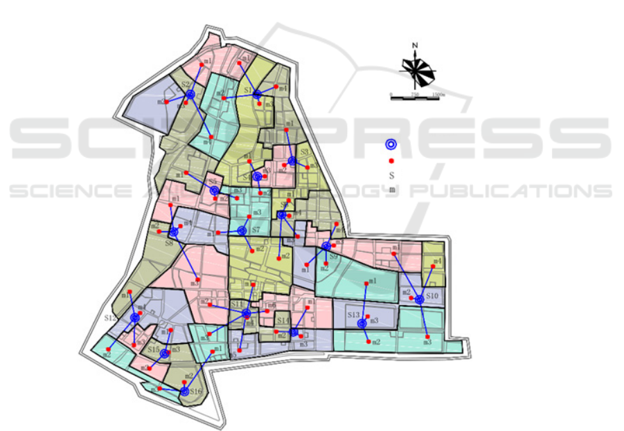
6 A NUMERICAL EXAMPLE
The following example is to perform the routing of
10kV trunk lines in an urban area where there are 16
110kV substations, 387 channel segments, 227
network nodes and 58 supply areas.
The meshes produced by the presented method
are shown in Fig.3 (a). The adjacent patches with the
same filling colour belong to the same mesh, and
only two of them are radiation meshes for which
only the trunk line paths need to be found.
According to the generated meshes and the load
centres of supply areas, the routing results of trunk
lines are shown in Fig.3 (b) where the purple
channels contain 2 feeders, and the other channels
contain 4 feeders. For the line wiring modes of
different meshes, the typical modes such as double
loops, N-supplies and one-backup and multi-
segment moderate tie connection can be selected
according to the actual situations (such as the load
density, power supply capacity, economy and
operability).
Load center
Substation node
Supply area
(a) Generated power supply meshes
110kV substation site
ICVMEE 2019 - 5th International Conference on Vehicle, Mechanical and Electrical Engineering
314
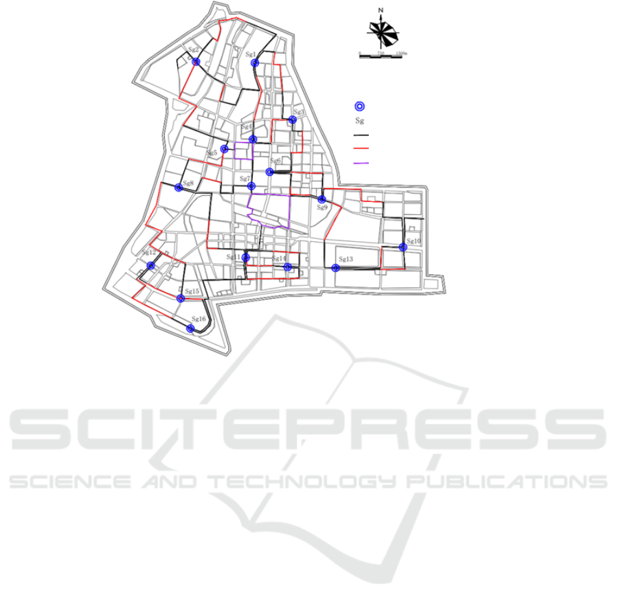
110kV substation site
Substation node
Trunk tie line path (4 feeders)
Trunk tie line path (2 feeders)
(b) Trunk line routing scheme
Trunk line path (4 feeders)
Figure 3. Generated power supply meshes and trunk line routing scheme.
7 CONCLUSIONS AND
DISCUSSIONS
A new method is proposed for the trunk line routing
for urban medium voltage distribution network
planning.
(1) A new thinking line is proposed for line
routing in this paper: based on generated meshes, the
routing of trunk lines is firstly performed along the
channels of a road network, and then the specific
scheme of user access to the trunk lines will be made
in the future when the locations of user access
facilities are known.
(2) To simplify the problem solution, the supply
areas are taken as the basic units of a power supply
mesh, and a power supply mesh may be taken as the
basic unit to carry out the trunk line routing. With
the constraints of channel resources and load centres
being satisfied, the shortest trunk line paths for all
supply areas and the shortest trunk tie-line paths for
all supply meshes are determined by a shortest path
algorithm.
(3) The proposed method results in a planning
scheme of clear power supply areas, reasonable
power supply radii and simple tie-lines, showing that
the method is practical and can provide a reference
for the trunk line routing of urban medium voltage
distribution network planning.
REFERENCES
GE Shaoyun, WU Qing, et al. Study on optimization of
the tie lines for urban medium voltage distribution
network [J]. Proceedings of the CSU-EPSA, 2005,
17(06): 43-49.
Gong Qu, Graph theory and network optimization
algorithm [M]. Chongqing: Chongqing University
Press, 2009.
Gu yuan, Guiding principles for grid planning of
distribution network[S], State Drid Corporation of
China, 2018.
HUO Kailong, WANG Zhuding, ZHANG Daihong, et al.
Practical Method of Multi-stage Planning
Optimization for Large-scale Substation [J].
Proceedings of the CSU-EPSA, 2017, 29(5): 122-128.
Koutsoukis N C, Georgilakis P S, Hatziargyriou N D.
Multistage Coordinated Planning of Active
Distribution Networks [J]. IEEE Transactions on
Power Systems, 2017:1-1.
LI You, CHANG Xianrong. Distribution network
intelligent planning consider feeder line automatic
layout and tie-line wiring investment [J]. Automation
of Electric Power Systems, 2012, 36(14): 30-35.
LU Zhi-ying, TIAN Shuo, CHENG Liang, et al.
Automatic planning about single loop distribution
Power Supply Meshes based Line Routing for Urban MV Distribution Network Planning
315

network based on improved ACO [J]. Proceedings of
the CSU-EPSA, 2014, 26(06): 47-53.
Ming Xu, Wang Zhuding, Wang Jingyu, etc. Medium-
voltage Distribution Network Planning Based on Mesh
Optimization Generation [J]. Automation of Electric
Power Systems, 2018, 42(22):232-242.
Song Meng, Liu Jian, Liu Gongquan. Urban distribution
network planning based on optimal partition-ing [J].
Relay, 2005, 33(23): 31-35.
Wang Jingyu, Wang Zhuding, Zhang Yongbin, et.al.
Three Layer Macro Network Constraint Based
Precision Planning of Middle Voltage Distribution
Networks [C]. Proceedings of 2018 3rd International
Conference on Electrical Engineering, Mechanical
Engineering and Automation (ICEEMEA2018), 2018:
13.
Wang Yujin. Substation Planning through Decreasing
Initial Redundant Substation in Meshes. [D].
Chongqing: College of Electrical En- gineering of
Chongqing University, 2011.
WANG Zhuding, QIU Jun. An efficient algorithm for
assessing reliability indexes of general distribution
sys-tems. IEEE Transactions on power systems, 2002,
17 (3): 608-614.
ICVMEE 2019 - 5th International Conference on Vehicle, Mechanical and Electrical Engineering
316
