
Integral Paraphrase of Physical Parameters of Non-uniformly
Induced Medium in Optical Current Transformer
Dong Yin
1, a
, Zhizhong Guo
1, b
, Guoqing Zhang
1, c
, Wenbin Yu
1, d
, Guizhong Wang
2, e
, Caiyun Mo
1, f
1
School of Electrical Engineering and Automation Harbin Institute of Technology Harbin, China
2
Research Institute of Industrial Technology Harbin Institute of Technology Zhangjiakou, China
f
853766565@qq.com
Keywords: Optical effect, non-uniformly induced medium, Jones Matrix, average uneven angle, average induction
angle, global phase shift difference.
Abstract: The three global physical quantities is presented to reveal optical sensing properties of a non-uniformly
induced medium. The study found that, the sine function of average induction angle is the weighted integral
of sine function of induction angle of optical path; the exponential function of average uneven angle is the
weighted integral of exponential function of uneven angle of optical path; the global phase shift difference
is the weighted integral of induced birefringence of optical path. The values verify that physical quantities
have a specific but non-approximate integral relation with the corresponding physical quantity of optical
path.
1 INTRODUCTION
The optical medium generates the optical effect
under the action of the physical field. The physical
field distributed along the optical path is sometimes
uniform, but sometimes not. Uniform case is an
exception of uneven cases, and the non-uniform
physical field is more universal. The uneven
physical field results in that the eigen coordinate
system of optical medium changes along the optical
path, unless the induction angle is constant. This
optical medium is a non-uniformly induced medium
(Xiao Zhihong, et al, 2017), and its Jones Matrix is
obviously different from that of the uniform medium.
Jones Matrix describes the input and output
relations of optical medium on the whole and its
basic physical parameters belong to the whole
medium (S.–Y.Lu and R. A. Chipman, 1994; Kyung
S. Lee, 1999; S.–Y.Lu and R. A. Chipman, 1994;
Sergey N. Savenkov et al, 2007; No´e Ortega-
Quijano et al, 2015; Alessandra Orlandini et al, 2001;
H. Kogelnik, L. E. Nelson, J. P. Gordon, and R. M.
Jopson, 2000). As for the non-uniformly induced
medium, the induction angle, uneven angle and
induced birefringence of the optical path cross
section are distributed unevenly. Intrinsically, the
global physical quantity depends on the physical
quantity of optical path. The relations between
average induction angle and induction angle of
optical path, between average uneven angle and
uneven angle of optical path and between global
phase shift difference and induced birefringence of
optical path are in close contact with each other.
Reference (Xiao Zhihong, et al, 2017)
established the three-part analytical expression with
the property of determinant of unitary matrix, laying
a model basis for analyzing the optical effect of
uneven physical field. In this paper, based on the
research of reference (Xiao Zhihong, et al, 2017),
the relational expression between global physical
quantity and physical quantity of optical path is
deduced with the Jones Matrix recurrence formula.
The result indicates that the global physical quantity
is the weighted integral of the corresponding
physical quantity of optical path.
2 INDUCTION ANGLE
PROPOSITION
A. The first recurrence relation of Jones Matrix
The non-uniformly induced medium is equally
divided into n+1 infinitesimal element. The
infinitesimal element Jones Matrix is
280
Yin, D., Guo, Z., Zhang, G., Yu, W., Wang, G. and Mo, C.
Integral Paraphrase of Physical Parameters of Non-uniformly Induced Medium in Optical Current Transformer.
DOI: 10.5220/0008384102800287
In Proceedings of 5th International Conference on Vehicle, Mechanical and Electrical Engineering (ICVMEE 2019), pages 280-287
ISBN: 978-989-758-412-1
Copyright
c
2020 by SCITEPRESS – Science and Technology Publications, Lda. All rights reserved
(1)
The infinitesimal element is sufficiently small,
and is regarded as uniform. So,
And
(2)
Where, indicate the complex number field and
indicate the real number field;
is the
induction angle of the optical path and
is the infinitesimal element phase shift
difference.
The cascade Jones Matrix constituted by the first
infinitesimal elements
(3)
Where,
.
According to reference (Xiao Zhihong, et al,
2017), the three-element expression of the diagonal
and non-diagonal elements of Jones Matrix
is
indicated below
(4)
Where
,
and
are respectively the
average induction angle, average uneven angle and
phase shift difference of Jones Matrix
.
It can be easily proved that the cascade Jones
Matrix
accords with the recurrence relation
(5)
Using three-element expression of
, is
rewritten into
(6)
(7)
The following simple symbols are used for the
abovementioned two formulas
(8)
B. Induction angle proposition
Induction angle proposition: for the non-
uniformly induced medium, the sine function of
average induction angle is the weighted integral
of the sine function of induction angle
of the
optical path.
(9)
Where,
is the normalized integral
coefficient, namely,
(10)
Where, is the length of optical path of the
medium.
Prove: according to , the real part of non-
diagonal element
has the following equivalent
relationship
Note
So, the real part of non-diagonal element
is
rewritten into
(11)
Where,
,
.
The abovementioned formula means that the
following formula holds.
Integral Paraphrase of Physical Parameters of Non-uniformly Induced Medium in Optical Current Transformer
281

Note
(12)
Where,
is the coefficient which makes the
equation hold and then put it into
is given as
So
Note again
There,
Due to
So
In case the medium is uniform,
,
therefore
The proposition holds.
3 PHASE SHIFT DIFFERENCE
PROPOSITION
Phase shift difference proposition: For the non-
uniformly induced medium, the global phase shift
difference is the weighted integral of the induced
birefringence
of optical path, namely
(13)
Where, is wave length;
is induced
birefringence. The relation is met
(14)
Where, is the intrinsic birefringence index,
is the non-diagonal component of cross
section induction tensor, is the average
deviation of diagonal components of cross section
induction tensor and , Namely
(15)
Prove: the real relation of (6) is
(16)
Wherein
The second item of is a small quantity,
meaning although
The coefficient
must exist. As a result, the
following formula holds
Therefore
Where,
,
. Moreover, when the
medium is uniform, .
The abovementioned formula predicts
So
That is
Because of
So
The proposition holds.
Deduction 1: For the non-uniformly induced
medium, the average induced birefringence and the
ICVMEE 2019 - 5th International Conference on Vehicle, Mechanical and Electrical Engineering
282

induced birefringence of optical path satisfy the
weighted integral relation
(17)
Because of
,
It’s substituted into , deduction 1 is
establishment,
Deduction 2: in case of uniform medium and
approximately uniform medium,
(18)
When the medium is uniform,
. So,
deduction 2 holds.
4 UNEVEN ANGLE
PROPOSITION
A. The second recurrence relation of Jones Matrix
The optical medium is equally divided into 2n+1
infinitesimal elements. The adjacent infinitesimal
elements of the Jones Matrix are multiplied with
each other in succession to obtain the Jones Matrixes
of n+1 combined infinitesimal elements. Without
loss of generality, the three-part expression of the
Jones Matrix
element is expressed as follows,
assuming the induction of combined infinitesimal
element is uneven.
(19)
Where
is the uneven angle of the combined
infinitesimal element , and its value is
(20)
Where the subscripts and respectively
indicate the first and second infinitesimal elements
of the combined infinitesimal element , and
(21)
Obviously, the uneven angle
of combined
infinitesimal element is the function of induction
angle differential .
The first combined infinitesimal element
Jones Matrixes are multiplied in series to obtain the
cascade Jones Matrix
. According to the
recurrence relation of (5), the three-element
expression form of Jones Matrix
can be obtained.
The non-diagonal element is
(22)
Where, the simple symbol of (8) is adopted.
B. Uneven angle proposition
Uneven angle proposition: For the non-uniformly
induced medium, the exponential function of the
average uneven angle is the weighted integral of
the exponential function of uneven angle
of
optical path
(23)
Where,
is the integral coefficient irrelevant
to the uneven angle of optical path. The relation can
be met.
(24)
Prove: according to , the non-diagonal
element meets the relation
Wherein
Where
,
.
This is similar to the verification of induction
angle proposition, so
According to (12),
Note
So
Integral Paraphrase of Physical Parameters of Non-uniformly Induced Medium in Optical Current Transformer
283

Because
,
When the medium is uniform,
So
The proposition holds.
Deduction: The uneven angle proposition can be
transformed into
(25)
Obviously, (21) can be written as
Therefore, the deduction holds.
5 VALUE VERIFICATION
The numerical method is adopted to verify the
abovementioned three propositions.
A. Verification method
If the changing rule of cross section induction
tensor along optical path is known
(26)
Where, when ,
is real symmetric, e.g.,
electric light, sound light, elastic light and other
effects, when ,
is complex symmetric,
e.g., magneto-optic effect.
According to the formula
(27)
The induction angle of optical path is calculated.
According to (14), the induced birefringence
of optical path is calculated
. Then,
according to the formula
(28)
The phase shift difference
of the
infinitesimal element is calculated.
The value will be large enough, and the
medium optical path is equally divided into
infinitesimal elements, namely
(29)
When the uneven angle proposition is verified,
the number of infinitesimal elements needs to be
doubled so that the infinitesimal element uneven
angle can be calculated according to (20).
Starting from the first infinitesimal element, all
infinitesimal elements are calculated. When the th
infinitesimal element is calculated, the Jones Matrix
is
(30)
So, the average induction angle
, average
uneven angle
and phase shift difference
of Jones Matrix
are already known. According
to the formulas
(31)
(32)
(33)
The average induction angle
, average uneven
angle
and phase shift difference
of Jones
Matrix
are obtained. So, because of
These are obtained
ICVMEE 2019 - 5th International Conference on Vehicle, Mechanical and Electrical Engineering
284
(34)
The abovementioned traverse calculation starts
from the starting end of medium and lasts until the
end. Therefore, three weight coefficient series of the
whole optical path can be obtained
(35)
The existence of the above-mentioned three
weight coefficient sequences is a numerical
verification for the induction angle proposition, the
uneven angle proposition and the phase-shift
difference proposition.
B. Verification case
The DOCT simulation model was created with
ANSOFT software of infinite element analysis to
conduct a simulated analysis on the integral
paraphrase and physical parameters of non-
uniformly induced material parameters. The initial
condition is set as: magneto-optic glass length is
0.05m, the vertical distance from its structural center
to conductor is 0.02m, and the linear birefringence
of magneto-optic glass is 3º/cm.
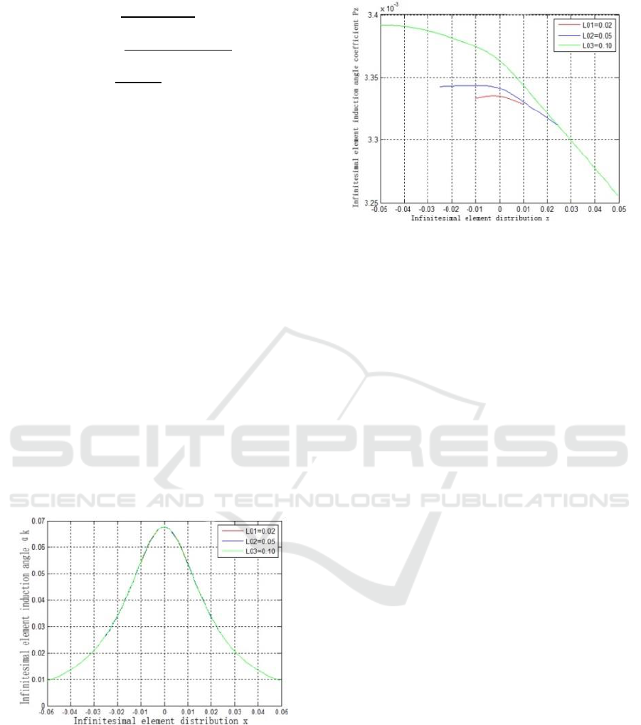
Fig 1. Infinitesimal Element Induction Angles with
Different Lengths.
Fig 2. Weighting Coefficients of Average Induction
Angles with Different Lengths.
As shown in Fig. 1, the infinitesimal element
induction angles at a same point of magneto-optic
glass with different lengths are the same, indicating
the induction angle is the function of the space
magnetic field, only depends on the space position,
and takes on the symmetric feature of an even
function around the conductor. When the
infinitesimal element is vertical to the conductor
center, the induction angle has a maximum value. As
shown in Fig. 2, the weighting coefficient of
infinitesimal element induction angle is a monotonic
decreasing function. When magneto-optic glass
, the infinitesimal element weight coefficient of
starting end is 1% more than that of terminal end;
when , the starting end is 4.5% larger than
the terminal end, and it tends to occur that the
difference between the weight coefficients of the
starting and terminal ends gradually increases as
increases. When the horizontal ordinate of the
selected conductor center is 0, the absolute value
of the derivative of the infinitesimal element
weighting coefficient on the left of magneto-optic
glass is smaller that of the right of the same,
indicating that the induction effect of the
infinitesimal induction angle on the integrity tends to
decline as the space position deviates.
(2) Infinitesimal element uneven angle and
weighting coefficient
The magneto-optic glass of L=0.02m, 0.05m and
are selected to calculate the infinitesimal
element induction angles of different positions and
their weighting coefficients. The simulation result is
shown in Fig.3 to Fig. 6.
Integral Paraphrase of Physical Parameters of Non-uniformly Induced Medium in Optical Current Transformer
285
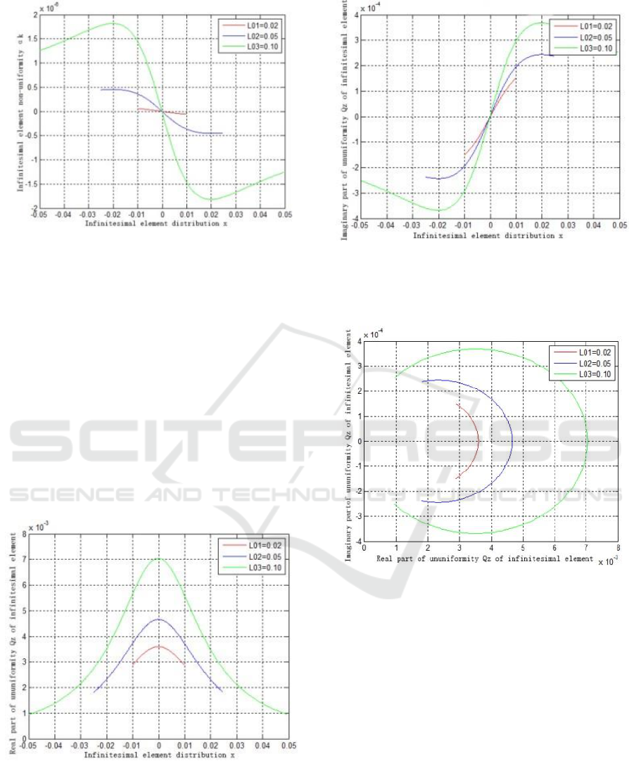
Fig 3. Unevenness of Infinitesimal Elements with
Different Lengths.
As shown in Fig. 3, the infinitesimal element
uneven angle increases as the deviation position
increases. And the infinitesimal element uneven
angle is 0, when the infinitesimal element is vertical
to the conductor center. Different from infinitesimal
element induction angle, infinitesimal element
uneven angle is affected by the sensor element
length except for depending on space position. . For
the infinitesimal element of the selected position
, the infinitesimal element uneven angle of
sensor length is 60% larger than
, indicating that the sensor element length
magnifies the non-uniformity of the infinitesimal
element.
(a) Real Part of Weight Coefficient
(b) Imaginary Part of Weight Coefficient
Fig 4. Average Uneven Angle Weighting Coefficient with
Different-Lengths.
Fig 5. Average Uneven Angle Weighting Coefficient of
Different Lengths (complex plane).
Judging from the deduction of , the weight
coefficient of infinitesimal element uneven angle is
complex. As shown in Fig. 4 and Fig. 5, the real and
imaginary parts of average uneven angle weighting
coefficient of different lengths takes on the
symmetric features of an even function and an odd
function. They increase the change degree of weight
coefficient as the sensor element length increases.
ICVMEE 2019 - 5th International Conference on Vehicle, Mechanical and Electrical Engineering
286
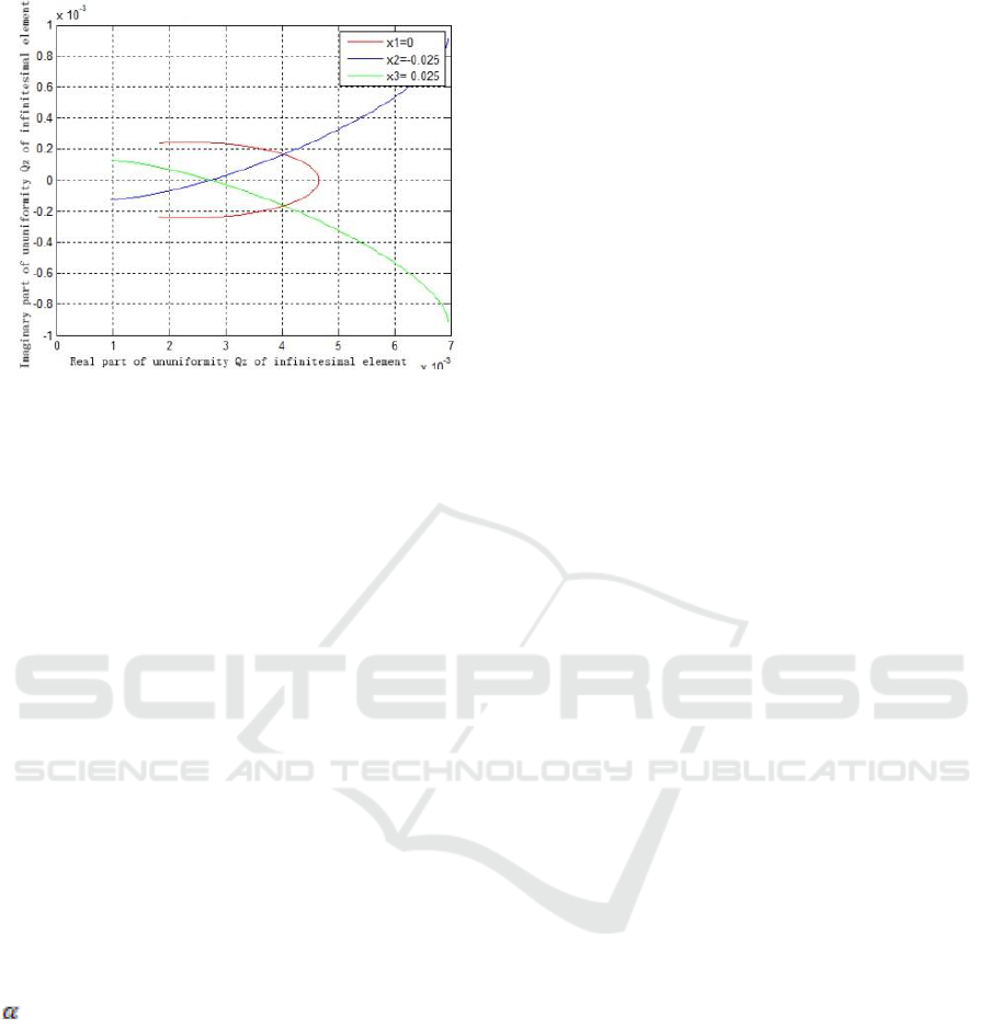
Fig 6. Average Uneven Angle Weighting Coefficient of
Different Deviation Layouts (complex plane).
The selected sensor element lengths are the same,
the simulation curve of all infinitesimal element
uneven angle weighting coefficients in case of
different deviation positions is shown in Fig. 6. With
the sensor element center deviating towards the left
or right, the non-uniformly induced degree
increases, the real and imaginary parts of the non-
uniform weighting coefficient no longer have the
symmetric feature but instead the monotonic feature,
and tend to increase progressively on the complex
plane.
6 CONCLUTION
The whole physical quantity of non-uniformly
induced medium depends on the physical quantity
of optical path, and accords with the specific but
non-approximate weighted integral relations.
Specifically:
(1) The sine function of average induction angle
is the weighted integral of the sine function of
induction angle
of the optical path.
(2) The exponential function of average uneven
angle
is the weighted integral of the exponential
function of uneven angle
of optical path.
(3) The global phase shift difference
is the
weighted integral of induced birefringence
of
optical path, i.e., the average induced birefringence
is the weighted integral of induced birefringence
of optical path.
REFERENCES
Alessandra Orlandini et al, “A Simple and Useful Model
for Jones Matrixto Evaluate Higher Order
Polarization-ModeDispersion Effects,” IEEE
photonics technology letters13 (11), 1176–1178
(2001).
H. Kogelnik, L. E. Nelson, J. P. Gordon, and R. M.
Jopson, “Jones matrix for second-order polarization
mode dispersion,”Opt. Lett. 25, 19–21 (2000).
Kyung S. Lee, “New compensation method for bulk
optical sensors with multiple birefringences,”Appl.
Opt. 28(11), 2001–2011 (1999).
No´e Ortega-Quijano et al, “Generalized Jones matrix
method for homogeneous biaxial samples,” Opt. Soc.
Am. A 23, 20428–20438 (2015).
S.–Y.Lu and R. A. Chipman, “Homogeneous and
inhomogeneousJones matrices”. Opt. Soc. Am. An 11,
766–773 (1994).
S.–Y.Lu and R. A. Chipman, “Homogeneous and
inhomogeneous Jones matrices”. Opt. Soc. Am. An
11, 766–773 (1994).
Sergey N. Savenkov et al, “Eigen analysis of dichroic,
birefringent, and degenerate polarization elements a
Jones-calculus study,” Appl. Opt. 46(20), 6700–6709
(2007).
Xiao Zhihong, Guo Zhizhong, Zhang Guoqing, Yu
Wenbin, Yu Tongwei, Li Zhiliang. “Study on the
Faraday optical rotation effect of inhomogeneous
magnetic field” Proceedings of the CSEE, 2017,
37(08):2426-2436.
Integral Paraphrase of Physical Parameters of Non-uniformly Induced Medium in Optical Current Transformer
287
