
Design and Implementation of Big Data Cloud Platform Supporting
Fault Diagnosis and PHM System for Switch Equipment
Long Shi
1, a
, Rong Zhou
1
and Shulin Tan
1
1
Beijing National Railway Research & Design Institute of Signal & Communication Group Co. Ltd, South Road of
Automobile Museum, Beijing, China
Keywords: Switch equipment, PHM, fault diagnosis, cloud platform.
Abstract: Switch equipment plays an important role in railway signal system with the high failure rate. Ensuring the
good work condition of railway switch equipment is of great significance for the safety and efficiency of
railway transportation. Based on technologies such as information sensing, Internet of Things, cloud
computing, expert system, artificial intelligence and fault prediction and health management (PHM), a
structure design of the fault diagnosis and PHM system for switch equipment is put forward. A big data
cloud platform, gathering and managing massive data reflecting the working state of switch equipment, is
designed and implemented. It will be a powerful support for the system to reduce failure rate and improve
operation and maintenance capability of switch equipment.
1 INTRODUCTION
As an important railway signal equipment, railway
switch equipment is an indispensable part of
ensuring the safe operation of trains. At present, the
monitoring method of switch equipment relies on the
data of switch action current and voltage in the
centralized monitoring system of manual browsing,
which has the shortcomings of poor intelligence and
high leakage rate (Su K.Y., et al, 2007). The major
railway bureaus in China generally adopt the mode
of periodic maintenance and post-fault maintenance
to maintain the switch equipment (Li N. and Dong
H.Y, 2013). The health status of the switch
equipment can not be obtained in time. The
maintainers who are not rich in experience can not
accurately judge the causes of the switch equipment
faults. It is difficult to form an effective maintenance
plan (Zhang X., Du X.S. and Liu C.Y, 2009).
In order to adapt to the new situation of railway
development, a system for the real-time monitoring
and fault diagnosis of the railway switch equipment
with modern technology needs to be established
(Gao C., Zhou W.X. and Zhang Y.B, 2016). It is a
general trend to improve the interconnection, data
sharing and intelligence level, eliminate data islands,
combine information sensing, artificial intelligence,
big data, cloud computing, Internet of Things and
other technologies. Build an intelligent switch
equipment fault diagnosis and PHM system to solve
the existing problems and meet the growing demand
is an important foundation for railway integrated
operation and maintenance platform.
2 STUCTURE DESIGN OF THE
FAULT DIAGNOSIS AND PHM
SYSTEM
2.1 System Description
The fault diagnosis and PHM system of switch
equipment is based on information sensing, wireless
communication for data transmission, building big
data cloud platform and configuring station
customer service terminal, combing fault diagnosis
and prediction algorithms, expert knowledge
database, artificial intelligence, etc.
Big data cloud platform provides data source and
serves as the basis for switch fault diagnosis and
PHM. Big data and cloud computing complement
each other. Data mining of big data relies on
distributed processing, distributed database, cloud
storage and virtualization technology of cloud
computing. Cloud platform is not limited by time
270
Shi, L., Zhou, R. and Tan, S.
Design and Implementation of Big Data Cloud Platform Supporting Fault Diagnosis and PHM System for Switch Equipment.
DOI: 10.5220/0008377302700273
In Proceedings of 5th International Conference on Vehicle, Mechanical and Electrical Engineering (ICVMEE 2019), pages 270-273
ISBN: 978-989-758-412-1
Copyright
c
2020 by SCITEPRESS – Science and Technology Publications, Lda. All rights reserved
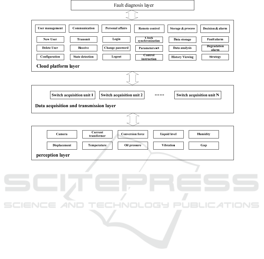
Figure 1. Structure of the fault diagnosis and PHM system for switch equipment.
and space, switch acquisition units transmit all kinds
of monitoring data to cloud platform through
wireless communication anytime. Large-scale data
management and calculation problems of switch
equipment are processed and solved.
PHM is a comprehensive subject related to the
study of systemic health management. It uses the
collected information to predict the system failure
effectively before it occurs through various
intelligent and self-learning algorithms and models
to assess the health status of the system. PHM is a
further expansion of built-in test and state
monitoring capabilities for complex systems
traditionally used. With the ability to predict future
faults of the system, it transforms traditional
condition monitoring into systematic health
condition management, the occurrence of faults can
be identified and managed. Then a reasonable
maintenance plan is planned to reduce the cost. The
maintainability, safety and reliability of the system
are improved, the condition-based maintenance and
self-support of the system are realized (Zeng S.K.,
Michael G.P. and Wu J,2005).
The application of PHM technology in switch
system and even the whole railway signal system
can describe the state of equipment through real-
time monitoring data. When the equipment is in a
healthy state, the system monitors continuously to
analyze the degradation types, define health level,
predict the possible future failure and formulate a
reasonable maintenance plan. When the equipment
is in failure state, the system sends alarm to identify
and position the failure, shortens fault diagnosis time
and improves diagnostic efficiency.
2.2 System Structure
The fault diagnosis and PHM system for switch
equipment collects various state parameters of
switch machine, external locking device, installation
device and switch environment online, monitors and
predicts the typical faults of switch equipment for a
long time, and forms a reliable fault diagnosis model,
which provides basis and decision-making reference
for routine maintenance. The system includes
sensing layer, data acquisition and transmission
layer, cloud platform layer and fault diagnosis layer.
The structure is shown in Figure 1.
Sensing layer consists of various sensors for
running and environment status information
collection of switch equipment, including camera,
displacement sensor, current transformer,
temperature sensor, conversion force sensor, oil
pressure sensor, liquid level sensor, vibration sensor,
humidity sensor and switch gap sensor.
Design and Implementation of Big Data Cloud Platform Supporting Fault Diagnosis and PHM System for Switch Equipment
271
Data acquisition and transmission layer is formed
by switch acquisition units with wireless
communication. An acquisition unit communicates
with sensors in the sensing layer to acquire switch
equipment data, and communicates with cloud
platform through wireless communication, such as
4G, Lora, NB-IoT, etc.
Cloud platform layer is responsible for real-time
data transmission, data display, storage, statistical
analysis, remote communication, condition
monitoring, fault handling, management and other
functions.
Fault diagnosis layer reflects the actual situation
of the switch equipment with the functions of alarm,
early warning, fault diagnosis, fault prediction,
operation log, maintenance suggestion, etc.
3 DESIGN AND IMPLEMENT OF
THE BIG DATA CLOUD
PLATFORM
3.1 Function Description
Real-time data transmission with switch acquisition
unit.
Data display, storage, management and analysis.
Remote control of all switch acquision units.
Communication status monitoring.
Fault handling and alarm.
Event processing and decision making.
Safety protection.
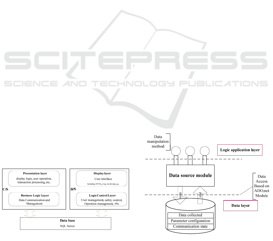
3.2 Software Structure
Cloud platform software consists of three parts: C/S,
B/S and database. As shown in Figure 2.
C/S of cloud platform is mainly used for
communication with switch acquisition unit. On the
one hand, the received data is stored in the database
for reading by B/S at the appropriate time; on the
Figure 2. Software structure of the cloud platform.
other hand, C/S sends user commands (operation
commands, switch acquisition unit parameter
configuration commands, etc.) to the switch
acquisition unit.
B/S of cloud platform processes user operations
and presenting system data and status to users.
The database is used to store data, including the
data received by C/S from the switch acquisition
unit, as well as the user's control instructions and
operation records. At the same time, the database
also plays the role of communication between B/S
and C/S. The control instructions of the user for the
switch acquisition unit are written to the database by
B/S, and then read and sent to the switch acquisition
unit by C/S.
3.3 C/S Design
Data source of C/S is used to interact with system
database. Database write and query services are
provided. The module encapsulates all the details of
accessing the database and provides transparent data
operation services for the upper layer.
Data source module of C/S is based on ADO.net
data access module. Strong data sets are used as data
manipulation intermediaries. The functions of the
data source module in the whole C/S section are
shown in Figure 3.
3.4 B/S Design
B/S of the cloud platform provides human-machine
interface for users to view the system status and data.
It is also responsible for interpreting the user's
operations, then the related operations are
transferred into commands and stored in the
database for C/S to read.
Figure 3. Data source module of C/S.
ICVMEE 2019 - 5th International Conference on Vehicle, Mechanical and Electrical Engineering
272
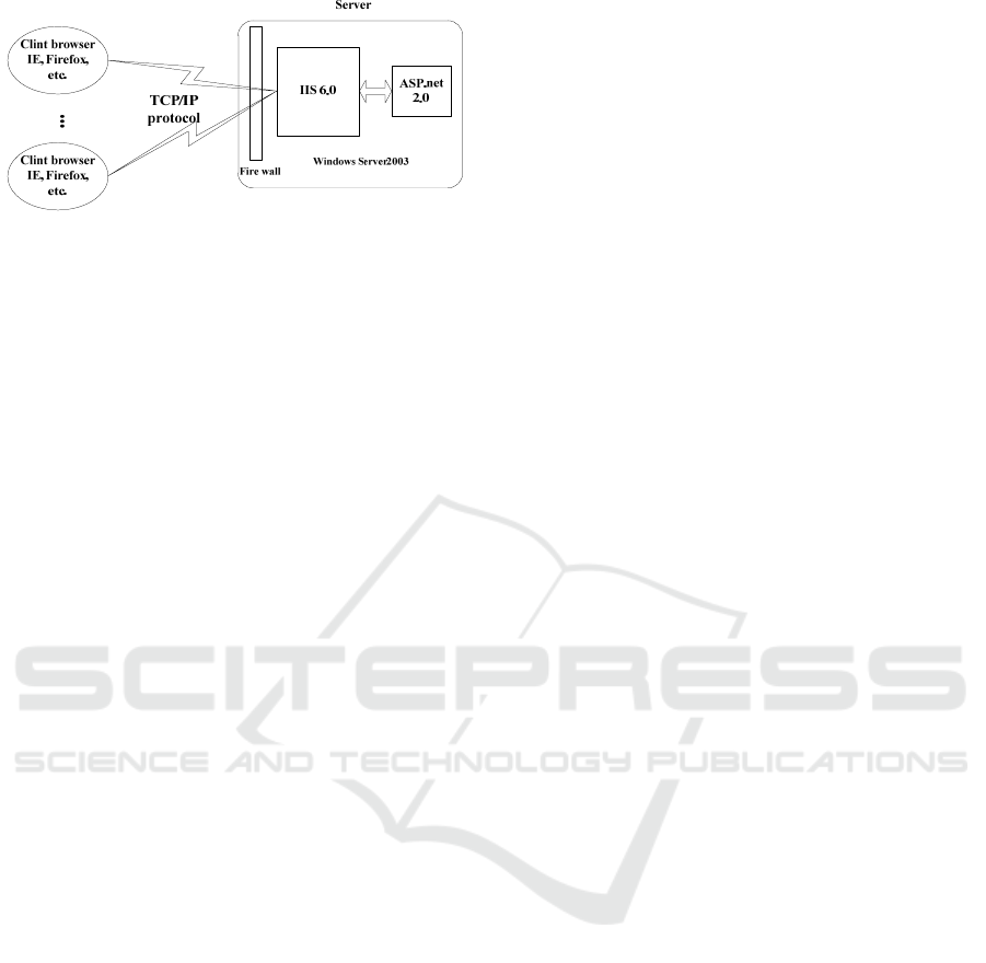
Figure 4. B/S network diagram.
The network part adopts the Web platform
provided by Microsoft IIS and uses ASP. NET as the
Web implementation method, as shown in Figure 4.
The server side runs Windows Server operating
system, which integrates IIS 6.0. The client side uses
IE and Firefox browsers, and the communicaiton
protocol between client and server is TCP/IP. clients
interact with the server by requesting ASPX web
pages. IIS receives the page request information
from client browser, locates the ASPX pages, and
sends the request information to ASP. NET module
for processing. ASP.NET module analyses ASPX
files, executes the server-side command code,
generates pure HTML documents, and returns them
to IIS. Finally, IIS returns HTML to the client
browser.
3.5 Safety Measures
Wireless VPN private network communication is
established, data is encrypted, and virtual servers are
replaced by physical independent cloud servers to
achieve physical isolation of data.
Clear the responsibility for security management,
check and strengthen the database system, server
operating system, application middleware and
system source code of cloud platform, improve the
overall safety of the system and ensure the normal
operation of the system.
Intrusion monitoring system is set up in the cloud
platform system to monitor the server operating
system, prevent virus from entering the server and
affect the cloud platform, prevent illegal personnel
from operating, and regularly analyze and check the
alarm information.
Strengthen the security of local network, design
the network structure rationally, devide the system
according to the importance of information, separate
the general server and the core server by logical
isolation, adopt higher security strategy in the
control process, set up corresponding access control
rules, and reduce the safety risk of the cloud
platform.
According to the actual needs, configure and
optimize the cloud platform system, deploy security
software on the cloud platform to protect the
relevant information of the cloud platform system.
Strengthen the internal audit work, establish and
improve the application of security audit platform to
ensure that illegal operations are tracked, traced and
evidenced.
4 CONCLUSIONS
The fault diagnosis and PHM system based on big
data cloud platform achieves Internet of Things of
switch equipment by information sensing,
distributed acquisition and wireless communication.
Multiple status data of switch equipment are
collected, stored and analyzed. based on PHM,
expert system and artificial intelligence and
combined with specific failure modes such as
external locking block, closure adjustment and
indication adjustment, a mathematical model to
characterize the corresponding relation between
switch equipment work state and fault modes can be
established. On one hand, the system can locate fault
position and diagnose fault causes, and guide on-site
maintenance. On the other hand, the health status of
switch equipment can be predicted, and the
condition-based predictive maintenance strategy can
be effectively executed.
REFERENCES
Gao C., Zhou W.X. and Zhang Y.B., 2016. Research
Situation and Development on Detection Technology
of Railway Turnout. Machinery, Vol. 7 No 43, p. 34-
38.
Li N. and Dong H.Y., 2013. Research on Fault Diagnose
Method of Switch Equipment Based on Information
Fusion. Railway Operation Technology. Vol. 19 No. 2,
p. 1-3.
Su K.Y., Chen H.Y. and Ouyang H.Z., 2007. Use
Artificial Intelligence to diagnose the fault of
speediness railway switch. Microcomputer
Information. Vol. 23, No. 8-1, p. 188-189.
Zeng S.K., Michael G.P. and Wu J., 2005. Status and
Perspectives of Prognostics and Health Management
Technologies. Acta Aeronautica et Astronautica
Sinica, Vol. 26 No. 5, p. 626-631.
Zhang X., Du X.S. and Liu C.Y., 2009. Development of
Railway Station Signalling Control Equipment Fault
Diagnosis Expert System. Journal of The China
Railway Society. Vol. 31, No. 2, p. 45-51.
Design and Implementation of Big Data Cloud Platform Supporting Fault Diagnosis and PHM System for Switch Equipment
273
