
Reliable Shadow Area Recovery with Two-Spatial-Frequency
Fringe Projections from Two Projectors
Yang Yang,
1
Wei Liu,
*
,
1
Yi Ding,
2
Yate Jiang,
1
Kai Peng
1
1
School of Electronic, Information and Communications, Huazhong University of Science and Technology, 1037 Luoyu
Road, Wuhan, Hubei, China
2
Wuyi University, Jiangmen, Guangdong, China
Keywords: Fringe projection profilometry, Three-dimensional reconstruction, Fringe analysis, Phase measurement.
Abstract: Shadow always appears on the captured fringe images in traditional fringe projection profilemtry system. To
recover the shadow area, in existing methods, fringe patterns from multiple projectors are employed to calculate
the absolute phase maps of entire object surface. However, if the fringe order errors in the absolute phase maps
were not corrected, significant errors would appear on the reconstructed three-dimensional result. In this paper
we propose a method to recover the entire surface profile with the fringe projections from two projectors. In the
proposed method, the shadow areas are identified, a novel technique is developed to correct the fringe order
errors in the absolute phase maps of the fringe patterns from two projectors, thus the reliability of shadow area
recovery could be improved. This method also can be used for various applications in industries and academics.
The methodology is exemplified with experimental data.
1. INTRODUCTION
Fringe projection profilometry (FPP) is considered
as a promising noncontact measuring method to
obtain three-dimensional profile data in industries
for product surface inspection and visual navigation
for decades (R. Leach,2011)(J. Geng,2011). In FPP, a
set of sinusoidal fringe patterns from micro-mirror
device is generated and projected onto the surface
of measured object and the light signals are captured
by a CCD camera. Due to the nature of structured
light illumination, shadow occurs in the capture
image when the projected illumination signal is
blocked by the shape of measured object. As the
shadow areas of captured image hardly reflect the
modulated light signals associated with object
surface, the captured signals in shadow areas cannot
be directly employed for three-dimensional
reconstruction. To eliminate the effect of shadow
areas in the captured fringe patterns, Lu et al. (L. Lu
et al,2015) developed a method to determine the
shadow areas by mapping the reconstruction depth
result to digital micro-mirror-device plane in pixel-
by-pixel manner.
The shadow areas in captured fringe image are
mainly resulted from the geometry of traditional
fringe projection profilometry system, if the fringe
patterns from different illumination angles could
cover the entire surface and their reflections are
captured by camera, it is possible to recover the
entire profile data. Skydan et al. (O. A. Skydan,2005)
employed the fringe images from multiple angles to
obtain the entire profile 3D reconstruction result.
Cai et al. (Y. Cai et al,2007)
proposed the inverse projected fringe technique
based on multiple projectors to recover the shadow
area more efficiently. Some methods have been
developed to improve the accuracy and robustness
of entire surface acquisition from multiple angles
for entire shape acquisition (W. H. Su,2008)(X.
Liu,2012). However, in these methods, fringe
patterns of only one spatial frequency is used, errors
may occur to the absolute phase maps due to the
complex object surface and shadow areas. Servin et
al. (M. Servin et al,2013) proposed a co-phased
profilometry to convert the phase demodulation of
multiple camera-projector systems into a single
process. In this method, the wrapped phase
extraction can be considered as an extension of the
standard Fourier Transform, thus the reconstructed
result is sensitive to the intensities of background
illumination and projected light signal. The points
of shadow areas generated by each projector may
affect the reconstruction results of the areas without
shadow. Furthermore, the sensitivities of the fringe
patterns from multiple projectors should be the
same to keep the accuracy of measurement, which
is difficult to satisfy in many applications.
Yang, Y., Liu, W., Ding, Y., Jiang, Y. and Peng, K.
Reliable Shadow Area Recovery with Two-Spatial-Frequency Fringe Projections from Two Projectors.
DOI: 10.5220/0008096702430250
In Proceedings of the International Conference on Advances in Computer Technology, Information Science and Communications (CTISC 2019), pages 243-250
ISBN: 978-989-758-357-5
Copyright
c
2019 by SCITEPRESS – Science and Technology Publications, Lda. All rights reserved
243

This paper proposes a method to improve the
reliability of the 3D profile recovery in shadow
areas with the two projectors in two angles. In
particular, this paper focuses on the case that, for
each projection, the fringe patterns generated by
projector can be reflected by the object surface and
are acquired by the camera. Only parts of the surface
are shadow areas, which are not illuminated by the
fringe pattern of projector.
The proposed method improves the reliability of
the shadow area recovery as follows. The points in
the shadow areas generated by each projector are
identified, the corresponding wrapped phase values
are labeled as invalid. For the points in the areas
illuminated by each projector, the corresponding
wrapped phase maps and absolute phase maps are
calculated with phase-shifting algorithm and two-
spatial-frequency temporal phase unwrapping,
which avoids the influence of the points in shadow
areas. For the possible fringe order errors in the
absolute phase maps around the shadow areas, we
develop a novel fringe order correction technique to
correct these errors. With the proposed method, the
profile of shadow areas generated by each projector
can be recovered. Finally, the complete 3D profile
could be obtained with high reliability.
The rest parts of this paper are organized as
follows. In Section 2 we present the identification
of points in shadow areas. In Section 3, reliable
absolute phase recovery for the fringe patterns
generated by each projector is developed. In Section
4, the method to recover the complete 3D profile is
developed. In Section 5, the experiments are
presented to confirm the method. Section 6
concludes the whole paper.
2. PRINCIPLE OF FPP AND
SHADOW AREA
IDENTIFICATION
2.1 Principle of FPP
Fig.1 shows the system structure diagram of
traditional fringe projection profilometry, which
includes one projector and one camera. Fringe
patterns are generated and projected onto the object
surface and reference plane. Camera acquires these
fringe pattern images for surface profile recovery.
For the area illuminated by projector, the
information of surface profile is modulated into the
deformed fringe pattern, thus it is possible to
reconstruct the surface of object with the captured
fringe images. In existing methods, wrapped phase
extraction should be implemented to obtain the
information of fringe pattern for height distribution
reconstruction. Among various wrapped phase
extraction and phase unwrapping methods, phase
shifting algorithm are the most widely used for the
reliability and the avoidance of the influences from
adjacent pixels, which can eliminate the effects
from the points in shadow area.
Figure 1: System structure diagram of traditional
FPP.
For the N-step phase shifting algorithm, the
fringe patterns captured by camera could be
expressed as
0
2 ( 1)
( , ) ( , ) ( , )cos(2 ( , ) )
c
n
n
d x y A x y B x y f x x y
N
(1)
where
1,2,3,...,nN
;
0
( , ) 2x y f x
is the
designed absolute phase map in the projector,
0
f
is
the spatial frequency of the fringe pattern;
( , )A x y
denotes the average intensity,
( , )B x y
denotes the
intensity modulation of the sinusoidal fringe pattern,
( , )xy
is the wrapped phase. When
3N
,
( , )A x y
,
( , )B x y
and
( , )xy
can be calculated as,
1
1
( , ) ( , )
N
c
n
n
A x y d x y
N
(2)
22
11
2 2 2
( , ) [ ( , )sin( )] [ ( , )cos( )]
NN
cc
nn
nn
nn
B x y d x y d x y
N N N
(3)
1
1
( , )sin(2 / )
( , ) arctan
( , )cos(2 / )
N
c
n
n
N
c
n
n
d x y n N
xy
d x y n N
(4)
Define
( , )
( , )
( , )
B x y
xy
A x y
(5)
where
( , )xy
denotes the data modulation, it is
always used as the index to evaluate the quality of
the fringe pattern (S. Zhang,2006). Higher
( , )xy
means the better fringe quality.
To recover the surface profile of object, phase
unwrapping should be implemented to obtain the
CTISC 2019 - International Conference on Advances in Computer Technology, Information Science and Communications
244

absolute phase from wrapped ones calculated by
phase-shifting algorithm in Eq.(4) . The relation
between absolute phase and wrapped phase is
expressed as
( , ) 2 ( , ) ( , )x y m x y x y
(6)
where
( , )m x y
denotes the fringe order, which is in
integer,
( , )xy
is the absolute phase. When the
absolute phase maps of the fringe patterns on object
( , )
D
xy
and on reference plane
( , )
R
xy
are
obtained, the difference of the absolute phase maps
( , )xy
, where
( , ) ( , ) ( , )
RD
x y x y x y
,
is used to calculate the height distribution of the
surface profile of object as:
0
00
( , )
( , )
2
x y l
h x y
df
(7)
where
0
l
and
0
d
are the parameters calibrated
before the measurements.
2.2 Shadow Area Identification
Due to the geometry in traditional fringe projection
profilometry in Fig.1, shadow always occurs in the
captured images. The shadow areas in the captured
images do not reflect the modulated light signal of
the projected fringe patterns. When phase shifting
algorithm or other wrapped phase extraction
algorithm is directly used to the pixels in shadow,
errors will occur in the corresponding wrapped
phase value. These incorrect wrapped phase values
will cause the errors in the reconstruction of the
object. We use Fig.2 to illustrate the reason causing
the shadow in traditional FPP system.
Figure 2: Shadow area formation and absolute.
phase of illuminated area in FPP system.
The field of view of the camera and projector is
12c
E C C
and
12p
E PP
respectively. The light beam
p
E PS
emitted from the projector reaches point
S
through point
P
on the object. Since the light beam
is blocked by the object through point
P
, shadow
area
2
PO S
is formed. The camera acquires the
fringe patterns in another direction, so the shadow
area
2
PO S
will be captured by the camera, which
does not reflect the modulated light signal to the
camera. Thus the pixels in the image acquired by
camera can be divided into two types of area as the
fringe pattern area and shadow area.
To identify the surface profile in shadow areas,
the points in shadow can be recognized by checking
whether the captured fringe patterns are from the
digital micro-mirror device plane (L. Lu,,2015).
Theoretically, if the points of the results calculated
by phase-shifting algorithm were mapped to the
digital micro-mirror device plane, the mapped
points from the shadow area will be out of the
boundary of digital micro-mirror device plane.
Therefore the points in shadow area can be
determined through this mapping. Since the
wrapped phase values in shadow areas are not
reliable, we label these values as invalid to
distinguish from the points in the area illuminated
by projector.
3. RELIABLE ABSOLUTE PHASE
RECOVERY
3.1 Absolute Phase Map Recovery with
Temporal Phase Unwrapping
To calculate the absolute phase and fringe order of
the surface with shadow, we take one section from
point
1
C
to point
2
C
shown in Fig.2 as an example.
1
C
,
2
C
,
1
O
,
2
O
,
P
,
S
are used to represent the
coordinates of the corresponding points on the
section respectively. For simplicity, we use
()x
and
()mx
to denote absolute phase
( , )xy
and
fringe order
( , )m x y
respectively. In Fig.2, the
areas from point
1
C
to point
P
and from point
1S
to point
2
C
are illuminated with fringe
projections, the area from point
1P
to point
S
is
the shadow. Based on the shadow area identification
in (L. Lu,2015), the unreliable absolute phase values
in shadow from point
1P
to point
S
are also
labeled as empty values. For the area illuminated by
fringe projections, the point on the fringe image
captured by camera is one-to-one map to the point
in digital micro-mirror device plane. Therefore,
when the absolute phase and fringe order in the
areas illuminated by fringe projections are correctly
Reliable Shadow Area Recovery with Two-Spatial-Frequency Fringe Projections from Two Projectors
245

recovered, the absolute phase should be
monotonically increasing, the fringe order should be
stepwise increasing. So the absolute phase from
point
1
C
to point
P
and from point
1S
to point
2
C
keeps monotonically increasing, we also have
( 1) ( )SP
(S. Zhang,2006). Since the fringe
order from point
1
C
to point
P
and from point
1S
to point
2
C
is stepwise increasing, we also
have
( 1) ( )m S m P
(S. Zhang,2006).
In order to recover the absolute phase map of the
surface with shadow, temporal phase unwrapping is
used due to its independence of the wrapped phase
values of adjacent pixels. In temporal phase
unwrapping, the fringe order of absolute phase is
uniquely determined with selected multiple-spatial-
frequency fringe projections(H. O. Saldner,1997)(Liu,
Y. Wang,2010).
However, when the noise in wrapped phase map
exceeds the phase error tolerance bound, errors may
occur in the fringe orders recovered by temporal
phase unwrapping (Y. Ding,2012)(L. Song,2014),
which makes the recovered fringe order value
different from its true value. To illustrate the fringe
order error in the recovered absolute phase, we
show an experiment results shown in Fig.3. In this
experiment, we project two sets of fringes at the two
normalized spatial frequencies 8 and 15 onto the
measured object, the normalized spatial frequency 8
means the image is covered with 8 complete fringe,
the normalized spatial frequency 15 means the
image is covered with 15 complete fringes. We label
the wrapped phase, fringe order and absolute phase
of the points in shadow areas as invalid, which are
indicated as empty in Fig.3(a) and Fig.3(b). The
wrapped phase maps of the area illuminated by
fringe projections are obtained with phase-shifting
algorithm (X. Su,1992), the corresponding fringe
orders are recovered with temporal phase
unwrapping method in (Y. Ding, 2011). The
recovered fringe order and absolute phase and of
section y=690 at the normalized spatial frequency
15 are shown in Fig.3 as follows.
(a)
(b)
Figure 3: The recovered fringe order (a) and the
recovered absolute phase (b) of section y=690 at the
normalized spatial frequency 15.
From Fig. 3, we notice that few points are with
fringe order errors in the area illuminated by fringe
projections, thus it is necessary to correct these
errors for high reliable temporal phase unwrapping.
3.2 Fringe Order Error Correction for
the Absolute Phase Separated by
Shadow Areas
For the surface without shadow, some methods find
and amend the fringe order errors by checking the
numerical difference of the calculated absolute
phase values between neighbor pixels (H.
Wang,2015)(C. Zhang,2015) or designing the filter
window size according to this difference (D.
Zheng,2017). Since the absolute phase and the fringe
order of the area illuminated by fringe projections
are separated into several intervals by shadow areas,
these correction methods cannot be used for the
surface with shadow areas.
To correct the fringe order errors occurring in
the absolute phase map separated by shadow areas,
we have the discussion as follows. According to the
physical meaning of fringe order, the section of
fringe order map is divided into some steps by the
fringe projections, the fringe order values of the
points in each step should be the same. The bounds
of steps can be found by checking the phase
discontinuities in wrapped phase map, the bounds
of shadow areas are also considered as the bounds
of step. The diagram of step division is shown in
Fig.4.
Figure 4: Step division separated by shadow area.
CTISC 2019 - International Conference on Advances in Computer Technology, Information Science and Communications
246

Thus when the fringe order values of the pixels
in one step are not the same, the fringe order error
must occur in this step. Since the noise in temporal
phase unwrapping can be modeled as Gaussian
distribution with the mean as the true fringe order
value (Y. Ding,2017), thus most of the fringe order
values of the pixels in each step recovered by
temporal phase unwrapping will be correct,
experimental results in many references confirm
this inference. Based on this inference, we can find
that in each step, it is high probability that the fringe
order value with the most pixels is the true fringe
order of this step. We consider this fringe order
value as the true fringe order of this step, the fringe
order values of the pixels in this step are all replaced
by this value.
If the fringe order value with the most pixels is
not the true fringe order, this processing can reduce
the random fringe order errors into the same wrong
fringe order value. The fringe order error is in
integer, thus the absolute phase error is in the times
of
2
. This kind of fringe order error can be found
by checking the difference of the absolute phase
values in this step with the nearest two steps. Along
the x-axis, one of the nearest two steps is on the right
side of this step, the other is on the left side of this
step. When this error occurs, the difference of the
absolute phase values will exceed pi, the increase
and decrease of absolute phase will appear in pair as
in Fig.3(b).
Therefore, for the surface with shadow, we can
summarize the technique to correct the fringe order
error of the absolute phase separated by the shadow
area as follows:
1. On the fringe order map recovered with
temporal phase unwrapping, divide the section of
fringe order map into several intervals row by row
based on the phase jump and bounds of shadow
areas in wrapped phase as Fig. 4., each interval
corresponds to one step.
2. Count the number of pixels for every fringe
order value in each step. If the fringe order value of
one step keeps the same, the fringe order value is
judged as true fringe order value of this step.
3. For the step with multiple fringe order values,
find the fringe order value with the most pixels. This
fringe order value is judged as the true fringe order
value, the other fringe order values are replaced by
this value.
4. Mark the steps corrected in Step 3. Compare
the absolute phase values on the bounds of these
steps with the absolute phase values on the bounds
of the two nearest steps. In the two nearest steps,
one is on the right side of the corrected step, the
other is on the left side of the corrected step. When
the increase of the absolute phase values on the
bounds of the two nearest steps exceeds
and the
decrease of the absolute phase values on the bounds
of the two nearest steps is less than
, we can
judge the fringe order value of the corrected step as
wrong. If such pair appears, we discard the absolute
phase values in the corresponding step since they
are not reliable. If there is no such pair, it means the
fringe orders are correctly fixed.
By this technique, we can detect and correct the
fringe order errors of the area illuminated by fringe
projections. Thus, the height distribution of such
area can be corrected with high reliability.
4. SHADOW AREA RECOVERY
WITH TWO PROJECTORS
From the discussion in Section 2, we can see that
the shadow area is formed when the illumination
signal emitted by projector is blocked by object
surface. To recover the surface profile in shadow
areas, information of fringe pattern in these areas
should be added. Based on this consideration, we
design a fringe projection profilometry system with
two projectors and one camera, the two projectors
are on the two sides of camera. For the objects with
convex surface profile, two projectors could cover
the entire surface. The diagram of this system is
shown in Fig.5.
(a) (b)
Figure 5: FPP system with two projectors and
one camera.
In Fig.5(a) and Fig.5(b), the shadow area formed
by the left projector can be illuminated by the right
projector, the shadow area formed by the right
projector can be illuminated by the left projector.
The object is illuminated by the fringe patterns
emitted by two projectors sequentially. By this
design, the shadow area from one projector can be
illuminated by another projector. The positions of
two projectors are on the symmetry of camera.
From the discussion in Section 3, we infer that
the possible errors in recovered fringe order values
Reliable Shadow Area Recovery with Two-Spatial-Frequency Fringe Projections from Two Projectors
247

could be corrected by the monotonic property of
absolute phase. Therefore, we design the
projections from the left projector as its true
absolute phase monotonically increasing along the
x-axis, the height distribution of can be obtained.
The projections from the right projector are similar,
the height distribution the area illuminated by the
fringe projection from left projector can be obtained.
The 3D profile of the shadow areas generated by
one projector can be recovered with the reliable
absolute phase of the fringe projections generated
by another projector, the complete three-
dimensional reconstruction result of object can be
obtained. For areas illuminated by two projectors,
we can decide which height value is used for 3D
profile reconstruction based on the quality
evaluation of fringe projection in Eq.(5).
We summarize the procedures to recover the 3D
profile of shadow area as:
1. Fringe patterns are casted onto the object from
two projectors sequentially as Fig.5 and make sure
that the shadow area generated by one projector is
covered by another one. For each projector, two-
spatial-frequency fringe patterns are casted. The
fringe projections from two projectors are designed
as Fig.5(a) and Fig.5(b) respectively.
2. For each projector, the points in the shadow
areas are identified by the method in Section 2.2,
which is proposed in [3], the wrapped phase values
of these points are labeled as empty. The wrapped
phase maps of the areas illuminated by fringe
projections are obtained by phase-shifting
algorithm.
3. For each projector, the absolute phase maps
of the areas illuminated by fringe projections are
obtained with temporal phase unwrapping. The
fringe order errors in the recovered absolute phase
maps are corrected by the novel technique
developed in Section 3.2.
4. The complete 3D profile data are
reconstructed with the corresponding reliable
absolute phase maps of the fringe projections from
two projectors by Eq.(7). For the areas illuminated
by two projectors, we decide which height value is
used based on the quality evaluation of fringe
projection with Eq.(5).
5. EXPERIMENTS
To exemplify the performance of the proposed
method, experiment is implemented. The purpose of
experiment is to show the proposed method could
recover the entire surface correctly. The test object
is a plaster model (Voltaire, the maximal z-axis
direction depth is 130mm), the shadow areas will
occur when these objects are illuminated by fringe
projections. The rich detailed of object surface is
suitable to illustrate the proposed method. Our
experiment system is set up with two projectors and
one camera, the experiment system is shown in
Fig.5. The camera in the experiments is Basler MV-
CS30G with its highest resolution
1296 966
, the
resolution of camera can be adjusted. The projector
is Acer H65010BD.
We use the fringe projection profilometry
system shown in Fig.5 to capture the fringe images
from the two projectors. The captured image is
composed of
648 480
pixels. For each projector,
we project the fringe image of two normalized
spatial frequencies 8 and 15 onto the objects.
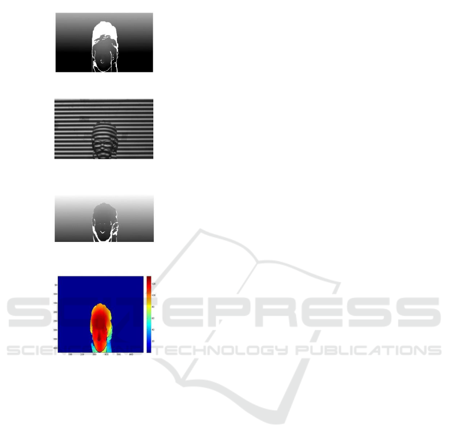
The fringe images from two projectors are
shown in Fig.6(a) and Fig.6(c). In these images, we
find some areas do not reflect the modulated light
signal to camera, which are formed as the shadow
area. The wrapped phase maps of the fringe
projections from two projectors are calculated by
phase shifting algorithm for noise reduction. The
shadow points can be found by the method in [3],
thus the wrapped phase values of shadow areas are
labeled as invalid. For the areas without shadow, the
absolute phase maps of these fringe projectors the
two projectors are obtained by the temporal phase
unwrapping developed in [22]. The fringe order
errors in absolute phase maps are corrected by the
technique described in Section 3.2, the corrected
absolute phase maps of the fringe patterns of two
projectors are shown in Fig.6(b) and Fig.6(d). The
absolute phase values in shadow areas are also
labeled as invalid, showing as the white parts in
Fig.6(b) and Fig.6(d) respectively.
With these absolute phase maps, we can obtain
two partial 3D reconstruction results. The complete
3D reconstruction result is obtained with the process
in Section 4, the entire three-dimensional
reconstruction result is shown in Fig.6(e), the unit
of depth data in z-axis direction is mm. We can see
the most parts of shadow areas in Fig.6(a) and
Fig.6(c) are recovered in Fig.6(e), there is no fringe
order error in the complete 3D reconstruction results,
thus the proposed method can recover the shadow
areas with high reliability.
(a)
CTISC 2019 - International Conference on Advances in Computer Technology, Information Science and Communications
248
(b)
(c)
(d)
(e)
Figure 6: (a) Fringe image from lower projector. (b)
Corrected absolute phase map of (a). (c) Fringe
image from higher projector. (d) Corrected absolute
phase map of (c). (e) Complete reconstructed 3D
profile.
6. CONCLUSION
This paper develops a method for entire surface
three-dimensional reconstruction with improved
fringe projection profilometry. To add fringe
information onto the shadow area, two projectors at
symmetrical positions are used to illuminate the
object surface. For the area illuminated by each
projector, points in shadow areas are identified,
phase-shifting algorithm and temporal phase
unwrapping are employed to avoid the influence of
the points in shadow area. The possible fringe order
errors in recovered absolute phase map are
corrected with the mathematical characteristics of
fringe order. Thus the 3D profile of shadow area for
one projector can be reconstructed by the fringe
projections from another projector with high
reliability. The method developed in this paper can
be applied to obtain entire surface profile for
industrial applications.
REFERENCES
R. Leach, Optical Measurement of Surface Topography,
1
st
. Edition, (Springer, 2011).
J. Geng, “Structured-light 3D surface imaging: a tutorial,”
Advances in Optics and Photonics, 3, 128-160
(2011).
L. Lu, J. Xi, Y. Yu, Q. Guo, Y. Yin, and L. Song,
“Shadow removal method for phase-shifting
profilometry,” Applied Optics, 54, 6059-6064
(2015).
O. A. Skydan, M. J. Lalor, and D. R. Burton, “Using
coloured structured light in 3-D surface
measurement,” Optics and Lasers in Engineering, 43,
801-814 (2005).
Y. Cai, and X. Su, “Inverse projected-fringe technique
based on multi projectors,” Optics and Lasers in
Engineering, 45, 1028-1034 (2007).
W. H. Su, C. Y. Kuo, C. C. Wang, and C. F.Tu, “Projected
fringe profilometry with multiple measurements to
form an entire shape,” Optics Express, 16, 4069-
4077 (2008).
X. Liu, X. Peng, H. Chen, D. He, and B. Z. Gao, “Strategy
for automatic and complete three-dimensional
optical digitization,” Optics Letters, 37, 3126-3128
(2012).
M. Servin, G. Garnica, J. C. Estrada, and A. Quiroga,
“Coherent digital demodulation of single-camera N-
projections for 3D-object shape measurement: Co-
phased profilometry,” Optics Express, 21, 24873-
24878 (2013).
S. Zhang and P. Huang, “Novel method for structured
light system calibration,” Optical Engineering, 45,
083601 (2006).
H. O. Saldner and J. M. Huntley, “Temporal phase
unwrapping: application to surface profiling of
discontinuous objects,” Applied Optics, 36, 2770-
2775 (1997).
K. Liu, Y. Wang, D. L. Lau, Q. Hao and L. G. Hassebrook,
“Dual-frequency pattern scheme for high-speed 3-D
shape measurement,” Optics Express, 18, 5229-5244
(2010).
Y. Ding, J. Xi, Y. Yu, W. Cheng, W. Wang and J.
Chicharo, “Frequency selection in absolute phase
maps recovery with two frequency projection
fringes,” Optics Express, 20, 13228-13251 (2012).
L. Song, Y. Chang, Z. Li, P. Wang, G. Xing, and J. Xi,
“Application of global phase filtering method in
multi frequency measurement,” Optics Express, 22,
13641-13647 (2014).
Reliable Shadow Area Recovery with Two-Spatial-Frequency Fringe Projections from Two Projectors
249

X. Su, W. Zhou, G. von Bally, and D. Vukicevic,
“Automated phase-measuring profilometry using
defocused projection of a Ronchi grating,” Optics
Communications, 94, 561-573 (1992).
Y. Ding, J. Xi, Y. Yu and J. Chicharo, "Recovering the
absolute phase maps of two fringe patterns with
selected frequencies," Optics Letters, 36, 2518-2520
(2011).
H. Wang, Q. Kemao, and S. H. Soon, “Valid point
detection in fringe projection profilometry,” Optics
Express, 23, 7535-7549 (2015).
C. Zhang, H. Zhao, and L. Zhang, “Fringe order error in
multifrequency fringe projection phase unwrapping:
reason and correction,” Applied Optics, 54, 9390-
9399 (2015).
D. Zheng, F. Da, Q. Kemao, and H. S. Seah, “Phase-
shifting profilometry combined with gray-code
patterns projection: unwrapping error removal by an
adaptive median filter,” Optics Express, 25, 4700-
4713 (2017).
Y. Ding, K. Peng, L. Lu, K. Zhong and Z. Zhu,
“Simplified fringe order correction for absolute
phase maps recovered with multiple-spatial-
frequency fringe projections,” Measurement Science
and Technology, 28, 025203 (2017).
CTISC 2019 - International Conference on Advances in Computer Technology, Information Science and Communications
250
