
Active Lower Limb Orthosis
with One Degree of Freedom for Paraplegia
Takuhiro Sunada
1
, Goro Obinata
1
and Yanling Pei
2
1
Department of Robotic Science and Technology, Chubu University, 1200 Matsumoto-cho, Kasugai 487-8501, Japan
2
Department of Electronic Control and Robot Engineering, Aichi University of Technology,
50-2 Nishihasama-cho, Gamagori 443-0047, Japan
Keywords: Assistive Robot Device, Lower Limb Orthosis, Active Control, Mechanism of Linkage, All in One.
Abstract: This paper describes a new design of active lower limb orthosis which is called as oneDHALO (one-actuator
Drive Hip and Ankle Linked Orthosis). The oneDHALO has a linking mechanism which connects both ankle
joints with a medial hip joint and an actuator which drives the rotation angle. The joints linkage mechanism
keeps feet always in parallel with the floor to avoid stumbling, and assists swinging of the leg. One servo
motor has been introduced to assist and control the movement constrained by the mechanism. To match the
active movement to walking phase, optical sensors have been introduced at the soles for detecting the distance
between the feet and floor. The control device which consists of internal communication system, sensor
interfaces and a single board computer (Raspberry Pi) is designed for all in one with the mechanical part of
the orthosis. The system has achieved continuous walking based on the feedback signals from the sensors.
This paper reveals the preliminary experimental results of the system to show the good points of the design.
1 INTRODUCTION
Several hip-knee-ankle-foot orthotic systems have
been developed
for
the bipedal locomotion of
paraplegics (Rose, K. G., et al., 1979). However,
most
of existing orthotic systems have problems in use;
1)
a large energy consumption for bipedal walking on
flat floor
(Stallard, J. and Major, E. R., 1998), 2)
bulky, 3) difficult to don/doff (Merati at al., 2000). To
solve those disadvantages, recent studies for lower
limb orthoses have aimed
at the usability with simple
and lightweight design (Kirtley, et al., 1996).
Problems of those systems are that the strides
were
short because the characteristic of the
horizontal rotation of
the pelvis in the orthosis,
otherwise the patient feel pain
(Saito et al., 1996,
1997). Genda et al. (2004) proposed an
orthosis,
HALO (Hip and Ankle Linked Orthosis), which
has
a link mechanism connecting ankle joints with a
medial
single hip joint. HALO partly solved the
problems of short strides
or large rotation of the
pelvis (Genda et al., 2004). The orthosis allows the
users to keep their
both feet always parallel with the
floor to avoid stumbling, and it
assists the swinging
of the leg when the contralateral ankle
is fixed
dorsally by loading. The energy consumption of the
user is a problem of HALO remained unsolved.
The
consumption energy of the users was
about
five
times larger than normal walking (Genda et al.,
2007). To reduce the
energy consumption of
walking with HALO, the authors proposed
an
extension of HALO w i t h one-actuator drive, which
is called as oneDHALO in our previous study
(Michal et al., 2017). In this paper, we describe a new
software development system and an all-in-one
design for oneDHALO.
The next chapter shows the mechanical
configuration and the motion behaviour of HALO. In
chapter 3, the extension with one actuator has been
proposed for the all in one system including the power
source. The active control system and the software
development system are proposed in chapter 3. The
comparison with another active assistive devices is
also given from the aspect of the usability,
performance and cost in the chapter. Chapter 4 shows
the concept of motion planning and the preliminary
experimental results. The role of each subsystem and
the system integration seeking suitable active motions
are explained. The preliminary experimental results
of the system are also shown to understand the good
points of this new design in chapter 5. The concluding
remarks are given in the final chapter.
504
Sunada, T., Obinata, G. and Pei, Y.
Active Lower Limb Orthosis with One Degree of Freedom for Paraplegia.
DOI: 10.5220/0007959905040509
In Proceedings of the 16th International Conference on Informatics in Control, Automation and Robotics (ICINCO 2019), pages 504-509
ISBN: 978-989-758-380-3
Copyright
c
2019 by SCITEPRESS – Science and Technology Publications, Lda. All rights reserved
2 MECHANICAL
CONFIGURATION OF HALO
The features of HALO come from the link
mechanism and the connections between the medial
hip joint and the ankle joints by Boden wires. The
hip
joint has two pulleys which rotate
independently around the same hip joint axis. Each
pulley is connected with the contralateral
knee-ankle-
foot orthosis. One Boden wire is set for coupling the
ankle
joint with a certain moment arm to the same
side
pulley at the hip joint. It is noted that the pulley
is
combined with the other side link, which is shown
in Figure 1. The wire of the other pulley is set in similar
manner for the other couple.
When dorsal flexion at
one ankle occurs with loading, the
wire connected
to the heel of the same side pulls and rotates
the
pulley of the hip joint connected with the
contralateral
knee-ankle-foot part of orthosis, and
then the generated torque at hip joint assists the
other
side leg in swinging forward.
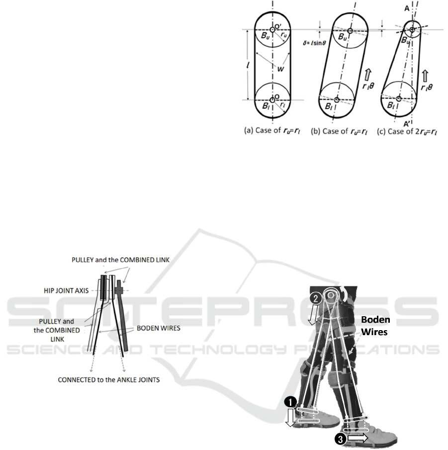
Figure 1: Medial hip joint and the connections.
The Figure 2 explains the operation of Boden wire
in sagittal plane. The lower bar B
l
is connected to
the foot link and rotates around the axis O; the
upper bar B
u
is connected to the contralateral link
system and rotates around O’. The Boden wire W
connects the two Bars to transfer the rotation of B
l
to the upper bar B
u
(See (a) in Figure 2). The tilt
occurs, then the loading around O by the foot link
keeps B
l
in the horizontal orientation. This causes
that the bar B
l
pushes the bar B
u
up r
l
θ, where θ
is the rotation angle of B
l
. When r
u
= r
l
, the bar B
u
rotates the same angle θ. This means that the bar
B
u
is always parallel to B
l
(See (b)). If 2r
u
= r
l
, the
bar B
u
rotates double (See(c)). In this case, the
contralateral link system connected to the bar B
u
as
shown in Figure 2 is in a symmetric position with
respect to the line A-A’. The Boden wire of the
contralateral link makes the lower bar in parallel to
Figure 2: Operation of Boden wire.
the bar B
l
. When r
u
= r
l
and the link works as
supporting leg, the clearance to the floor bigger
than lsinθwill be required for the swinging leg
(the contralateral link). In the case of 2r
u
= r
l
, the
swinging leg (the contralateral link) declines
oppositely the same angle as the supporting leg; the
lower bar is parallel to the floor. Moreover, the
height of the swinging leg is equal to the supporting
leg. This causes that zero clearance is required for
the swinging leg.
Figure 3: Schematic illustration of mechanism operation.
The illustration in Figure 3 explains the way in which
the link mechanism works as an assistive device for
walking with paraplegia. When the upper body
inclines forward, a certain amount of dorsiflexion
torque is generated at the ankle joint because the body
weight is loaded on the supporting leg. First, the
torque is converted by the lower bar to the force,
which pulls the wire to rotate the upper bar which is
just the pulley at hip joint. Second, the torque
generated at the hip joint rotates the contralateral
knee-ankle-foot orthosis (the swinging leg). Third, it
results in the forward swing of the contralateral leg.
Active Lower Limb Orthosis with One Degree of Freedom for Paraplegia
505
Moreover, the loop connection of the Boden wire
keeps the lower link at the ankle joint parallel to
the floor as explained above with Figure 2. This
means that the user can enjoy his/her foot clearance
of the swinging leg without being anxious while
walking with HALO.
3 CONFIGURATION OF ACTIVE
CONTROL SYSTEM
In previous study, Genda et al. (2007) revealed the
pelvic rotation with Loftstrand crutches helped
enough
for the physiologically normal level by the
gait analysis with HALO in
the experiments.
However, the consumption energy of the user was
five times larger than normal walking. In this
paper, one servo motor with a communication port
has been introduced to assist and control the
movement constrained by the mechanism of HALO.
All in one orthosis including power source is the
target for our new design. There are several ways
when active control is applied to HALO mechanism.
An active extension of HALO with two electric
motors was proposed (Lee et al., 2015), which is
called as powered HALO (pHALO). In the extension,
the problem is solved how two motors are set into the
one degree-of-freedom mechanism. The direct
introduction of two motors in the two Boden wires of
HALO’s both legs provides a function for changing
the relative positions between the three links at the
two joints, ankle and hip. The function was used for
Table 1: Comparison of HALO and powered HALO
(Obinata, G., et al., ,2015).
Stride
length[m]
Gait speed
[m/s]
Displacement
of CoG [m]
Power
[Nm/s]
HALO
617.9
×10
−3
m
225.5
×10
−3
m/s
51.6
×10
−3
m
12.9
Nm/s
pHALO
637.9
×10
−3
m
283.5
×10
−3
m/s
25.7
×10
−3
7.84
Nm/s
cf.
[%]
+3.23 % +5.76 % -50.2 %
-39.2 %
pushing up the supporting leg to decline the upper
body forward in pHALO. Experimental results of
such a function showed the advantageous effect on
strides, gait speed, fluctuation of body COG,
mechanical power as shown in Table 1. The results
looks good; on the other hand, the total weight of the
device including the orthosis was more than 12Kg.
Taking out the link mechanism with Boden wires and
setting four motors at hip joint and at knee joints make
a multi-actuated assistive device. Device called as
Rewalk (ReWalk Robotics, 2011) is a typical and
successful one with four actuators. If the control
scheme is good for the user, Rewalk may work well
because it has enough degree-of-freedom to achieve
an ideal motion for the user’s severity of impairment.
However, the weight is 22Kg and it is expensive.
Lighter weight of assistive device is desired for users’
handling and make it possible bring the device
everywhere.
To reduce the weight, only one motor
has been introduced into HALO in this pa per. With
one motor, the movement of HALO which is
described in Chapter 2 will be compensated by
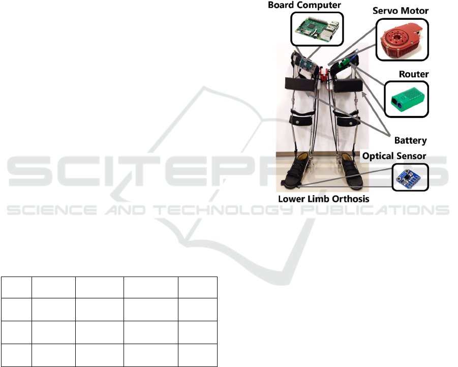
Figure 4: oneDHALO, the actuator and the sensors.
appropriate motor control scheme. The preliminary
results of one-drive HALO (oneDHALO) showed the
similar effects as powered HALO with two motors
(Michal et al., 2017). However, the device can work
only in the case that the control signal to the motor
and the electric power are provided from outside
through wires. In other words, the subsystems: the
controller, the sensor interface and the power source
were located outside of the HALO mechanism. On
the other hand, all in one system has been achieved
including the mechanism, the sensors, the actuator,
the controller, and the power source in a new design
of oneDHALO. To match the active movement to
walking phase, optical distance sensors (Ambient
light sensor, VCNL4010) have been introduced at the
soles of feet. The mechanical part, the actuator, the
power source, controller and the sensors are shown in
Figure 4. The control system which consists of
internal communication system (Ethernet), interfaces
for sensors and a single board computer (Raspberry
Pi) is designed for all in one with the mechanical part
of the orthosis, which is shown in Figure 5. The
ICINCO 2019 - 16th International Conference on Informatics in Control, Automation and Robotics
506
sensors have infrared emitter to analyze the
proximity, and transmit the measured distance to the
board computer (main controller) by I2C communica-
tion interface. The signals from the sensor are used
for the main controller to decide which leg is
supporting one. The total weight including the
mechanical part and the power source is 7.1kg. The
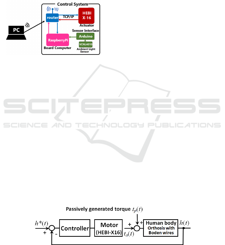
control system includes a router of TCP/IP, which
Figure 5: Software development system for oneDHALO.
communicates with a high specification personal
computer through Wi-Fi. The PC enjoys several kinds
of high-level programming languages for developing
the control algorithms of the active assistive orthosis.
In this design, the PC is used only for the software
development. The developed program for controlling
the active orthosis in real time will be sent to the
board computer, and be executed locally. The
actuator (HEBI X8-16, HEBI Robotics) is an
Ethernet-enabled device that integrates a brushless
motor, gear-train, a rotary encoder and control
electronics into a compact package. It runs on
standard DC voltages and communicates using
standard 10/100Mbps Ethernet. The module run a real
time operating system in the modules itself that
process commands and feedback at 1kHz. The
actuator accepts commands and responds to requests
to feedback through the network.
4 MOTION PLANNING AND
EXPERIMENT
4.1 Motion Planning
Assume that right leg is in supporting phase with
oneDHALO. When the motor gives torque of a
positive magnitude to swing the left leg forward, this
action assists the user’s walking forward. In this
situation, the torque of a negative magnitude
interferes walking forward. Hence, the controller
must detect which leg is in supporting phase. For this
purpose, proximity and ambient light sensing
modules (
VCNL4010) have been introduced for
measuring the distance between the feet and the floor.
The distance below a certain value means that the foot
is in supporting phase. To avoid malfunction of the
sensors due to unevenness of the floor surface, four
sensing modules are set for one foot. To plan the
motion of motor, the following parameters have to be
defined: the stride, the cycle time, and the assist level
of walking with the actuator. These parameters define
the pattern of hip joint angel while walking as in
Figure 7, or our simulation technology can generate a
suitable pattern for the hip joint angle (Obinata et al.,
2015). Assume that h*(t) is a cyclic function desired
for the hip joint. The following control system is
considered to achieve the desired motion of the hip
joint (See Figure 6). The controller is a simple
position controller with P, I, D elements for hip joint
angle h(t). The generated torque of hip joint is the
summation of the motor torque and the passive torque
generated by loading on the supporting leg. The
assistive level of active control can be adjusted by
tuning the controller parameters. The level of active
control L
a
is defined as follows:
=
|
()
|
/
(
)
(1)
The passive torque can be considered as a disturbance
for the controller. If the passive torque t
p
(t) is
satisfactory and enough to generate exactly the joint
motion h*(t), the active torque t
a
(t) generated by the
Figure 6: Proposed control system.
Active Lower Limb Orthosis with One Degree of Freedom for Paraplegia
507
motor takes zero. If the passive torque t
p
(t) is short,
then the active torque t
a
(t) compensates to achieve the
joint motion h*(t). Therefore, if we can define
available reference joint angle h*(t) as the
reference,the control system automatically achieves
the required torque by compensating for the passive
torque. From the energy efficiency viewpoint, the
timing for applying h*(t) to the control system has to
be matched to the generated passive torque. For this
purpose, the phase matching between the passive
torque and the reference joint angle is important. The
sensors at feet for detecting walking phase can
provide the signals for the phase matching of the
reference joint angle h*(t) to the passive torque.
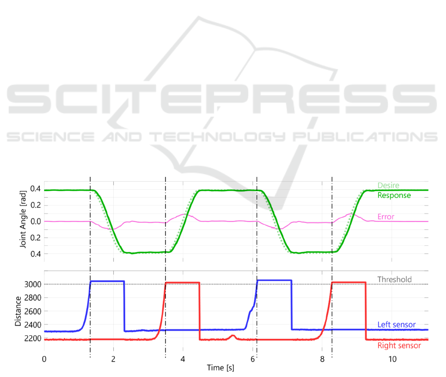
4.2 Experiment
Operation tests with the control system described
in the former chapter were conducted. The tests
were on the tracking performance of angle position
with a sinusoidal reference input and on the timing
problem with signals of the proximity sensors. The
tests was conducted without any load on the
actuator. The tracking performance of joint angle
to the reference was near perfect. The result is
shown in Fig. 7 with the signals of the proximity
sensor. It seems sufficient that the device achieves
a certain tracking performance and provides
enough assistive swing force to the user. The
control program made the actuator start when the
measured distance from the floor of the swinging
leg exceeded 2mm. This is the typical usage of the
proximity sensor. If the actuator starts before the
swing leg leaves the floor, it may cause turning in
situ. Signals from eight sensors (four sensors per
one foot) can be used to estimate upper body
movements of the user. Such estimation may be
useful to match the active assistive torque to the
passively generated torque specially for achieving
the coincidence between the two torques.
5 CONCLUDING REMARKS
This paper proposes a new design of active control
orthosis for paraplegic walking. After explaining
the operation of the link mechanism, the
configurations of the active control system and the
software development system are given. The total
weight including power source is 7.1kg, which is
the lightest device of active lower limb assistive
device for paraplegia in the world. This is achieved
because the device has only one electric motor as
the actuator and it works in concert with the
passively generated torque induced by the shift of
the upper body’s CoG (center of gravity). Finally,
the concept of motion planning and the preliminary
experimental results are given in this paper. The
tracking performance of active control system
indicates enough potential for the purpose of
assisting paraplegic walking in the preliminary
experiment. Moreover, the proximity sensors
introduced here will be useful for various control
schemes, which may provide the adaptability to
several types of the user. Defining and taking the
Figure 7: Reference, measured value of angle, and signals from the proximity sensors.
ICINCO 2019 - 16th International Conference on Informatics in Control, Automation and Robotics
508

timing of the reference input for the device
movement in concert with the user’s action or
intension is the main issue that should be solved in
further research.
ACKNOWLEDGEMENTS
This works is supported by JSPS KAKENHI Grant
Number JP16H03214. The authors thank to JSPS,
for the grant and to Dr. Genda for his original idea
of HALO.
REFERENCES
Genda, E.,Oota, K., Suzuki, Y., Koyama K., Kasahara, T.
(2004) “A
new walking orthosis for paraplegics: hip
and ankle linkage system,”
Prosthet Orthot Int, Vol.28,
pp.69-74.
Genda, E., Koyama, K., Oota, K., Suzuki, Y., Hayashi, M.
(2007) "Energy efficiency of walking with Hip and
Ankle Linked Orthosis: HALO," Gishisougu-
Gakkaishi (Journal of the Japanese Society of
Prosthetics and Orthotics), vol. 23, pp. 65-70, (in
Japanese).
HEBI X-SERIES ACTUATOR Ⓡ at: https://www.
hebirobotics.com/x-series-smart-actuators (Accessed:
20 April 2019).
Kirtley, C., McKey, K. S. (1992) “A medially-mounted
orthotic hip joint
for paraplegic walking systems
preliminary report on the polymedic
walker Device,”
Polymedic Technical Note, Australia.
Lee, J., Mizumoto, R., Obinata, G., Genda, E., Stefanov, D.,
Aoki, H., et al. (2015) "Gait generation for powered
Hip-Ankle-Linkage-Orthosis," Engineering in
Medicine and Biology Society 37th Annual
International Conference of the IEEE, pp. 5732-5735.
Merati, G., Sarchi, P., Ferrarin, M., Pedotti, A., Veicsteinas,
A. (2000)
“Paraplegic adaptation to assisted-walking;
energy expenditure during
wheelchair versus orthosis
use,” Spinal Cord, vol.38, pp.37-44.
Michal, G., Obinata, G., Genda, E., Babjak, J., Pei, T.
(2017) “Active lower limb orthosis with one degree of
freedom for people withparaplegia,” International
Conference of Rehabilitation Robotics of the IEEE,
pp.258-263.
Moore, P., Stallard, J. (1991) “A clinical review of adult
paraplegic patients
with complete lesions using the
ORLAU Para Walker,” Paraplegia, vol.
29, pp.191-196.
Obinata, G., Mizumoto, R., Lee, J., Genda, E., Hase, K.
(2015) "Simulation of knee-locked walking for
designing powered orthosis," Engineering in Medicine
and Biology Society 37th Annual International
Conference of the IEEE.
Rewalk, 2011. at: https://rewalk.com/ (Accessed: 20 April
2019)
Rose, K. G. (1979) “The principles and practice of hip
guidance articulations,”
Prosthet Orthot Int, vol.3,
pp.37-43.
Saitoh, E., Suzuki, T., Sonoda, S., Fujitani, J., Tomita Y.,
Chino, N. (1996)
“Clinical experience with a new hip-
knee-ankle-foot orthotic system
using a medial hip
joint for paraplegic standing and walking,” Am J
Phys
Med Rehahil, vol.75, pp.198-203.
Saitoh, E., Baba, M., Sonoda, S., Tomita, Y., Suzuki M.,
Hayashi, M. (1977)
“A new medial single hip joint for
paraplegic walkers,” In Proc. The
world congress of the
international rehabilitation medicine association,
Kyoto Japan, August 31, pp.1299-1305.
Stallard, J., Major, E. R. (1998) “A review of reciprocal
walking systems
for paraplegic patients: factors
affecting choice and economic justification,” Prosthet
Orthot Int, vol. 22, pp.240-247.
Active Lower Limb Orthosis with One Degree of Freedom for Paraplegia
509
