
Automated Shoe Last Customization using MATLAB Algorithm
T. Y. Pang
1 a
, K. H. Soh
1
, S. Ryan
2
and P. Dabnichki
1
1
School of Engineering, RMIT University, Bundoora Campus East, Bundoora VIC 3083, Australia
2
Glenrowan Enterprises T/A GoodFit Feet Sizing, 9 De Laeter Way, Technology Park, Bantley, WA 6073, Australia
Keywords: Shoe Last, Customization, Cycling, Automated, Algorithm, CAD.
Abstract: Footwear plays an essential role in human daily life as properly fitting and comfortable footwear will
significantly improve human lives and productivity. Footwear customisation techniques aim to manufacture
footwear that fits an individual’s foot geometric. Footwear that exactly fits a person’s foot geometric will
provide more support and reduce impact when walking or when doing other activities. A customised shoe last
is an important tool used by shoemakers in manufacturing customised shoes. Currently, most customised shoe
lasts are made from the moulds of clients’ feet and all the measurements are done manually, which is a tedious
and time-consuming process. This project aims to develop a novel MATLAB (2017) algorithm that will
shorten the shoe last customization process and do so with higher accuracy. This MATLAB algorithm can
reconstruct the foot model to smooth the surface texture and rearrange the three-dimensional (3D) model
vertices for easier dimension calculations. It can also locate makers on first and fifth metatarsophalangeal
joint automatically for more accurate shoe last design. The shoe last developed using the novel algorithm was
used to create its equivalent negative moulds for the manufacturing of carbon fibre cycling shoes. The negative
moulds were 3D printed and used to produce a prototype of cycling shoes. Future research needs to consider
developing an automated algorithm to create negative moulds to speed up the cycling shoe manufacturing
process.
1 INTRODUCTION
Footwear is necessary in human daily life, as it is
designed to protect the foot from external pressure
and improve walking and sports performance. Well-
fitting footwear is important to provide support and
enhance user comfort. Ill-fitting footwear can cause
injuries and foot shape deformation, which will
reduce gait quality (Terrier et al., 2009). Finding the
right pair of shoes with the correct fit is important for
athletes, particularly with the emergence of
competitive sports. Therefore, footwear must not only
be designed to fit the users properly and to improve
comfort, but also maximize athletic performance and
minimize injury (Luximon et al., 2009, Werd et al.,
2010).
Footwear customization is an essential aspect of
manufacturing footwear that fits an individual’s feet
geometrics and dimensions to improve fit and user
comfort (Davia et al., 2013). The shoe last is an
important tool that determines the design, shape, size
and, more importantly, the fit of the final product
a
https://orcid.org/0000-0002-4766-3042
during the footwear manufacturing process. The
production speed of shoe last is very important in
shoemaking industry, in order to decrease the overall
shoe production budget in terms of time and money
(Zhang et al., 2012).
There are two main methods in manufacturing
customised shoe lasts: (i) the traditional method; and
(ii) a computer-based method (Telfer et al., 2010). In
the traditional footwear manufacturing method, shoe
makers use plaster to form a client’s foot geometric
in a mould. Then, footwear will be made according to
the mould (Figure 1), normally known as shoe last.
The manufacturing of a shoe last through the
traditional method is done manually and through a
trial-and-error approach that is a purely artisanal and
based on the shoemaker’s experience to fit specific
feet dimensions. It is an arduous and complex process
that takes a lot of time to manufacture due to
constraints imposed by the manual measuring of
several feet’s dimensions (Leng et al., 2006).
Nowadays, with an increasing cost of labour even
in developing countries, there is great interest in
Pang, T., Soh, K., Ryan, S. and Dabnichki, P.
Automated Shoe Last Customization using MATLAB Algorithm.
DOI: 10.5220/0007949301170122
In Proceedings of the 7th International Conference on Sport Sciences Research and Technology Support (icSPORTS 2019), pages 117-122
ISBN: 978-989-758-383-4
Copyright
c
2019 by SCITEPRESS – Science and Technology Publications, Lda. All rights reserved
117
manufacturing and design automation in the footwear
industry. The footwear customisation process can
become a lot easier when a computer-aided design
(CAD) system is introduced into this process.
Shoemakers start by using a three-dimensional (3D)
camera to scan the plaster last and user’s feet (Figure
2) and then import the scan into CAD software for
further editing and processing (Weisedel, 2007). This
CAD modelling technique can speed up the
prototyping process of customising shoe lasts, which
saves manufacturing time and money (Jimeno-
Morenilla et al., 2013). 3D scanning and CAD
techniques can also recognise landmark positions on
a foot scan accurately for more reliable measurement
results, with less than a 2mm error (Luo, 2010).
However, due to the complexity of the data, the 3D
foot scan model post-processing and analysis process
can be tedious and time-consuming. Significant error
might occur during the analysis process because of
low consistency. After the 3D data has been post-
processed, shoe lasts will be produced through either
the additive manufacturing processes, such as 3D
printing, or the subtractive manufacturing processes
such as computer numerical control machining.
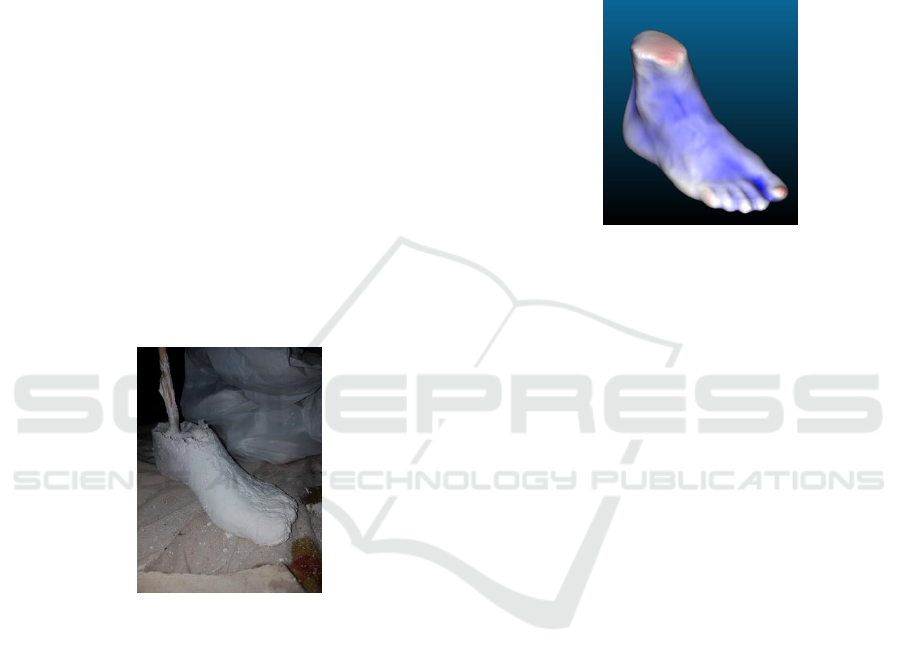
Figure 1: Plaster foot mould sample.
Cycling shoes, like many other footwear, has seen
a paradigm shift in its design and manufacturing
processes. Some manufacturers are now offering
custom-tailored and handcrafted cycling shoes to fit a
specific person’s feet. For instance, Simmons Racing
(Simmons Racing©, 2019) offers fully customised
cycling shoes made out of carbon fibre, but its process
requires manual casting of a mould, which is very
time consuming and costs about US $2000 a pair.
The cycling shoe is unique when compared with
other athletic shoes. The sole of the cycling shoe
serves as the rigid link between the foot and pedal,
whereas the pedal serves as a link between shoe sole
and crank arm of the bike (Werd and Knight, 2010).
Hence, cycling shoes normally have a stiff or rigid
sole. According to Langer (Langer, 2010), cyclists try
to fit their cycling shoes as snugly as possible to
minimize any motion of the foot inside the shoe in
order to maximize energy transfer to the foot-shoe-
crank arm interface. The foot arch, heel cup and toe
box structures are the three most important parts to
consider when designing a pair of customized cycling
shoes. These are the parts that are required to fit the
user’s feet perfectly to achieve maximum support and
minimum side-to-side pressure in the toe box area.
Figure 2: 3D scanned image of a user foot from plaster last.
Our project aims to develop an automated 3D
design algorithm to create a customised cycling shoe
last from the digital data scanned from an individual's
foot shape. It is envisaged that this novel algorithm
will reduce the time required for the post-processing
phase and improve consistency and accuracy when
reconstructing the raw scanned data. A reconstruction
method is applied in this algorithm because it can
repair holes in the foot model and smooth the surface
texture to reduce noise. The algorithm will speed up
manufacturing by casting a user's foot as a mould for
a bespoke shoe last to manufacture customised
cycling shoes.
2 METHODOLOGY
The detailed design process of the algorithm
foundation is presented in this section. It is separated
into (1) foot data collection, (2) post-processing, and
(3) the raw data sectioning concept development and
MATLAB code development phase.
2.1 Foot Data Collection
All 3D foot scanned data used in this project are
collected using an INFOOT 3D foot scanner (Figure
3(a)). Five markers were placed on a user’s feet
before the scanning process, as shown in Figure 3(b).
The INFOOT scanner produced the raw scanned data
as a binary CADfix Geometry Database File (FBD)
that includes the position of markers.
icSPORTS 2019 - 7th International Conference on Sport Sciences Research and Technology Support
118
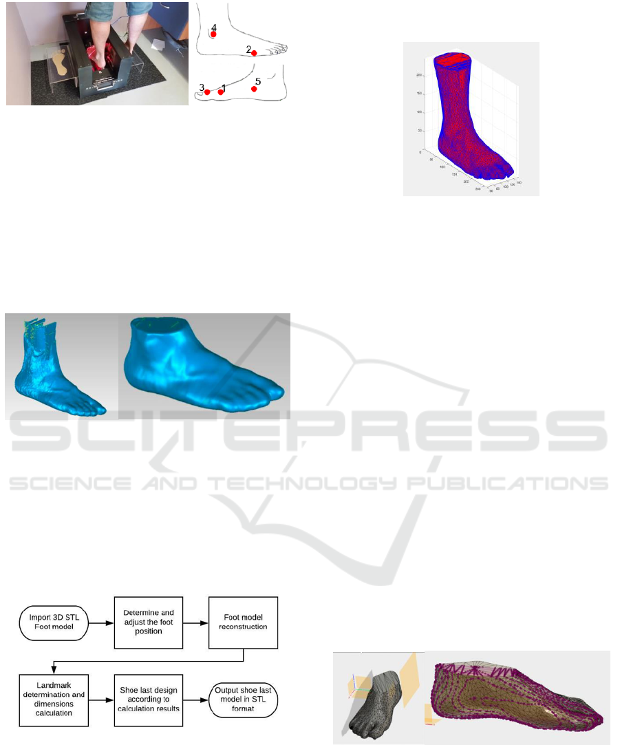
Figure 3: (a) Infoot scanner [I-Ware Laboratory Co., Ltd],
(b) Landmark locations.
2.2 Post-processing and Intersection
Foot Model Reconstruction
The raw scanned data were post-processed to remove
noise and unwanted parts, as well as to patch holes
using a CAD software. Figure 4 shows the raw
scanned data and the cleaned foot model after post-
processing in Standard Tessellation Language (STL)
format.
Figure 4: (a) Raw scanned data, (b) cleaned foot scan model
after post-processing.
2.3 MATLAB Script Development
MATLAB was used to develop an automated
algorithm that expressed matrix and array
mathematics directly. The flowchart in Figure 5
describes the brief MATLAB algorithm development
process.
Figure 5: MATLAB algorithm development process
flowchart.
The foot scan data was converted into a vertices
and faces matrix when imported into MATLAB by
using stlTools. Figure 6 shows the imported foot
model in MATLAB. All the vertices are connected by
faces triangles, which are presented in red, while blue
lines are the edges that form triangle faces.
Figure 6: 3D scanned foot model imported in MATLAB.
2.3.1 Determining the Position of the 3D
Foot Model
After the scanned foot data was imported into the
MATLAB environment, the first step was to detect
the pointing direction of the foot’s scanned data. Due
to the different system used to scan the user’s foot,
the position of foot models was not always placed on
x-axis; rather, they were randomly positioned on of
either positive or negative x and y axis. After
ascertaining the position of the foot model, the
algorithm needed to relocate the foot model to a fixed
positive x direction for the calculation of landmark
position.
2.3.2 Reconstructing the Foot Model
After that, the foot model needed to be reconstructed
to rearrange the vertices points of the foot model. A
foot sectioning needed to be considered before
developing the analysis algorithm to ensure that the
sectioning was clear and feasible. The sectioning
process was designed to cut out the unused part of the
foot scan model. Figure 7(a) shows the foot model
that has been sectioned at most lateral malleolus
height.
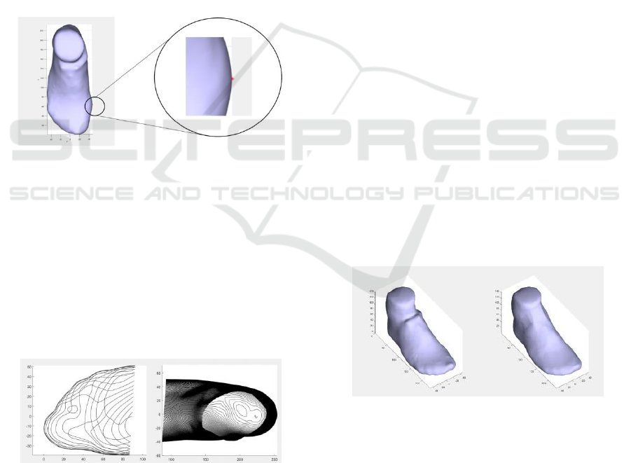
Figure 7: (a) sectioned foot model, (b) Intersection concept
testing on foot model.
The MATLAB code converted the 3D foot
scanned models from STL format into a ‘vertices’ and
‘faces’ matrix structure. Vertices express the 3-
dimensional coordination points of the foot model
Automated Shoe Last Customization using MATLAB Algorithm
119
and faces are the triangles connecting each vertex.
The vertices from the imported foot model are usually
random and messy, so an intersection method was
needed to rebuild the foot model to generate uniform
vertices for higher accuracy in the analysis of results
(Figure 7(b)).
2.3.3 Calculating the Landmark Location
The landmark position that was calculated in this
algorithm was the first Metatarsophalangeal (MTP)
joint, which joins the head of first metatarsal and
proximal phalanx of big toe. The reason that
approximating first MTP joint position needs to be
specifically calculated is for toe box development.
The first MTP joint is always the most prominent part
of the forefoot region for the general population.
Figure 8 shows the calculated landmark position on a
foot model.
Figure 8: Calculated first MTP joint landmark position on
foot model.
The red dot on the figure above shows the calculated
first MTP joint position on the foot model. The landmark
was used to separate the foot model into rearfoot and
forefoot sections. The separation was done by calculating
the instep and fibula instep length and separating the foot
from the cross section of these two points. This was done
because the customised shoe last required the geometric of
the rearfoot (e.g. foot arch and heel) and toe box. The
examples of separated forefoot and rearfoot parts are shown
in Figure 9.
Figure 9: Forefoot and rearfoot areas.
3 RESULTS AND DISCUSSION
3.1 MATLAB Algorithm
The novel algorithm we employed processed the 3D
foot scanned models in STL format by reconstructing
and calculating the landmark positions on the foot
model using the mathematical algorithm. The first
step of the algorithm detected the normal direction of
the imported foot model, then relocated it to the
positive plane for easier calculation.
The original scanned foot model was compared
with the reconstrued shoe last model constructed by
the MATLAB algorithm shown in Figure 10. It was
clear that the forefoot and rearfoot parts had a
different number of vertices points. This occurs
because a customised shoe last model keeps the
detailed geometrical shape of heel and arch parts, so
it needs more vertices points to provide the
information. In terms of the 3D model reconstruction,
it not only rearranges the vertices points but also
rebuilds the faces that link all the vertices points
together to form a closed 3D profile. This action was
done by a boundary function in MATLAB. The
boundary function can generate faces that connect all
the reconstructed vertices to form a 3D object, and the
details of the generated faces can also be controlled
by changing the boundary function coefficient
number. However, the boundary function cannot
completely cover every detail of the reconstructed
model. Holes will appear in some foot model data due
to the complexity of the input model and some
geometric information will disappear due to the
boundary error.
Figure 10: Reconstructed shoe last model, Original (left)
and result (right) of the 3D foot model.
An overlapped comparison between the original
and reconstructed model is shown in Figure 11. The
red part refers to the original foot model and the blue
part is the reconstructed model. The boundary error
can be minimised by reducing the number of
intersections produced during the reconstruction
phase.
icSPORTS 2019 - 7th International Conference on Sport Sciences Research and Technology Support
120
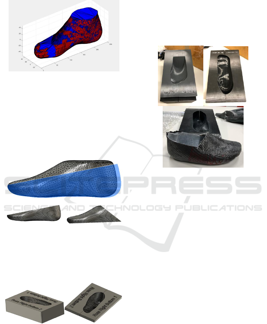
Figure 11: Overlapped comparison of original (red) and
reconstructed foot model (blue).
3.2 Shoe-last Customization and
Prototyping
The intention was to use the shoe last as a mould to
produce a pair of cycling shoe prototypes using
composites materials. The reconstructed foot model
was then split into two parts: the top and the bottom
parts (Figure 12).
Figure 12: The reconstructed foot model was sectioned into
two parts: top and bottom parts.
The top and bottom parts was then converted into
negative male and female moulds (Figure 13) for
manufacturing of carbon fibre cycling shoes through
composite layering.
Figure 13: Male and female mould for carbon fibre
manufacturing processes.
The output products of this algorithm were 3D
printed using Acrylonitrile Butadiene Styrene (ABS)
3D filament for prototype testing purposes. During
the manufacturing process, a multi-layer of composite
fiber materials was laid over the negative male and
females shoe last moulds. The moulds and composite
fibre materials were then placed into a vacuum bag to
shape the materials according to the shoe last’s design
(Figure 14).
Figure 14: 3D printed male and female moulds, and
porotype of carbon fibre cycling shoes.
4 CONCLUSIONS
The MATLAB algorithm developed in this project
successfully designed a shoe last from a raw STL file
automatically, regardless of the normal direction of
the original input model. It cleaned up the original
scan file by reconstructing the vertices of the 3D
model, which allowed further calculations. In other
words, the algorithm did significantly shorten the
shoe last customisation process to under two seconds,
as everything was done automatically by the
MATLAB algorithm.
The output shoe last model had an approximate
+/-2mm error difference from the original foot model,
which was deemed an acceptable result for accurate
shoe last design. Future development of this
algorithm will focus on improving the boundary
function and creating a better resolution of the
enclosed surface.
The output shoe last was converted into a negative
male and female moulds, 3D printed and tested by
using it in the actual shoe manufacturing process. We
created negative moulds based on the shoe last
developed by the novel customization algorithm, and
the attempt at producing a composite cycling shoe
Automated Shoe Last Customization using MATLAB Algorithm
121

was successful. Future work in this project will focus
on automating the negative mould development
processes.
ACKNOWLEDGEMENTS
The authors would like to thank the technical staff
from RMIT Advanced Manufacturing Precinct for
their help in 3D printing the prototypes. We would
also like to express our sincere thanks to Dr Floreanna
Coman for her valuable advice and assistance in
constructing the carbon fibre shoes.
REFERENCES
MATLAB and Statistics Toolbox Release 2017b academic
version The Mathworks, Inc, Natick, Massachusetts,
United States.
Davia, M., A. Jimeno-Morenilla and F. Salas (2013)
Footwear bio-modelling: An industrial approach.
Computer-Aided Design, 45, 1575-1590.
Jimeno-Morenilla, A., J. García-Rodriguez, S. Orts-
Escolano and M. Davia-Aracil (2013) 3D-based
reconstruction using growing neural gas landmark:
application to rapid prototyping in shoe last
manufacturing. The International Journal of Advanced
Manufacturing Technology, 69, 657-668.
Langer, P. 2010. Cycling. In Athletic Footware and
Orthoses in Sports Medicine, ed. M. B. W. a. E. L.
Knight. New York: Springer.
Leng, J. and R. Du (2006) A CAD Approach for Designing
Customized Shoe Last. Computer-Aided Design and
Applications, 3, 377-384.
Luo, S. 2010. Landmark design in 3D PDM for PCA of
shoe last. In 2010 3rd International Conference on
Advanced Computer Theory and
Engineering(ICACTE), V1-517-V1-521.
Luximon, A. and Y. Luximon (2009) Shoe-last design
innovation for better shoe fitting. Computers in
Industry, 60, 621-628.
Simmons Racing©. 2019. Simply The Best, Simply
Simmons. https://www.simmons-racing.com/.
Telfer, S. and J. Woodburn (2010) The use of 3D surface
scanning for the measurement and assessment of the
human foot. Journal of Foot and Ankle Research, 3, 19.
Terrier, P., O. Dériaz, A. Meichtry and F. Luthi (2009)
Prescription footwear for severe injuries of foot and
ankle: Effect on regularity and symmetry of the gait
assessed by trunk accelerometry. Gait and Posture, 30,
492-496.
Weisedel, W. (2007) Tru-Mold shoes brings automated
manufacturing techniques to the world of custom shoe
making. Podiatry Management, 26, 176-176.
Werd, M. B. and E. L. Knight. 2010. Athletic Footwear and
Orthoses in Sports Medicine. New York, NY: Springer
New York : Imprint: Springer.
Zhang, Y., A. Luximon, A. K. Pattanayak and M. Zhang
(2012) Shoe-last design exploration and customization.
The Journal of The Textile Institute, 103, 541-548.
icSPORTS 2019 - 7th International Conference on Sport Sciences Research and Technology Support
122
