
Depth Generation using Structured Depth Templates
Lei Zhang
Lenovo Research Center, Lenovo Group Ltd., Beijing, China
Keywords: Depth Map, Stereoscopic, Structured Depth Template.
Abstract: We propose a new stereoscopic image / video conversion algorithm by using a two-directional structured
depth model matching method. This work is aimed at providing an effect depth map to a 2D scene. By
analyzing structure features of the inputting image frame, a kind of depth model called structured depth model
is estimated to be as an initial depth map. Then the final depth map can be obtained by a depth post processing.
Subjective evaluation is performed by comparing original depth maps generated manually and generated from
the proposed method.
1 INTRODUCTION
Since 3D stereoscopic images provide higher realistic
viewing experience than conventional monoscopic
images, 3D stereoscopic technology and display
system (i.e. 3D-TV) are nowadays often seen as the
next major milestone in the ultimate visual experience
of media (Harman, 2000). An important part in any
3D system is the 3D content generation. However, the
traditional capture techniques with a single camera
leads that the tremendous amount of current and past
media data is in 2D format but in lack of 3D video
content. To evade this situation, 2D to 3D conversion
technology is used to convert a monoscopic image or
video movie to a stereoscopic image or video movie.
A necessary step of 2D to 3D conversion
processing is depth map generation, which recovers
the depth information by analyzing and processing
the 2D image. Some of conversion methods are using
image classification (Battiato et al., 2004), vanishing
line (Cheng et al., 2009), motion estimation
(Moustakas, 2005; Kim et al., 2007). In one side,
these methods are difficult to be processed in real
time because of higher complexity and more memory
needs. In another hand, some of them are just suited
to special scenes, like object motion scenes or outside
scene with vanishing line. So these methods have
some limitations to general applications, like 3D
home TV or broadcasting with various scenes.
In view of the foregoing, the intent of this paper is
to impart a new depth map generation algorithm by
using a two-directional structured depth template
matching approach (SDTM). In the proposed method,
a kind of initial component, named structured depth
template (SDT), is defined. Two SDTs for horizontal
and vertical directions are estimated respectively by
analyzing structure features of the inputting scene.
Then the final accurate depth map can be obtained by
a depth post processing. The SDTM method may be
applied in a real-time software or hardware system
because of the lower complexity and higher
performance.
2 DEPTH MAP GENERATION BY
SDTM
2.1 Main Architecture
The main architecture operates on an embodiment
described below with reference to figure 1. The whole
processing consists of several constitutive modules
At image preprocessing stage, the noise
reduction, gray conversion and resolution reduction
processing will be done, which can enhance accuracy
of depth estimation and also reduce the computational
complexity.
From template change detection to depth map
post processing stages, a depth map matching the
inputting scene will be estimated and generated. The
details of these stages will be described later.
Finally, the stereoscopic image pairs are
generated by using computed depth map and the
original video (Kim et al., 2007).
326
Zhang, L.
Depth Generation using Structured Depth Templates.
DOI: 10.5220/0007916903260330
In Proceedings of the 16th International Joint Conference on e-Business and Telecommunications (ICETE 2019) - Volume 1: DCNET, ICE-B, OPTICS, SIGMAP and WINSYS, pages 326-330
ISBN: 978-989-758-378-0
Copyright
c
2020 by SCITEPRESS – Science and Technology Publications, Lda. All rights reserved
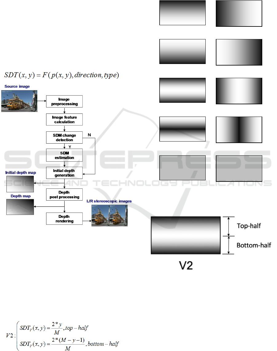
2.2 SDT Designation
Before describing details, a plurality of depth
structures called SDT are designed, which can
describe characteristics of a 2D scene in 2 dimensions
as shown in figure 2. There includes V0-V4 for
vertical direction and H0-H4 for horizontal direction.
The darker color denotes smaller depth, and the
brighter color denotes bigger depth. According to the
characteristics of structure, each independent SDT or
combination of several SDT can describe any scene.
To any SDT, depth value SDT(x,y) of position
(x,y) is a mapping of position p(x,y), direction and
type, which can be describes as follows.
(1)
Figure 1: SDTM’s architecture.
where direction means one of two directions,
including horizontal, vertical directions. Type means
one of 5 SDTs as shown in figure 2. The definition
domain of the mapping function F(p(x,y), direction,
type) is from MinDepth to MaxDepth, where
MinDepth and MaxDepth are the minimum and
maximum values of the expectable depth. In general,
they are 0 and 255.
The equation 2 describes an example of the
mathematic relationship for V2.
(2)
where M is height of the image. The structure of
V2 is shown in figure 3. Based on the same way, each
SDT can be easily calculated when it is required.
They don't need to be stored in memory.
Figure 2: Structured depth models for horizontal and
vertical directions.
Figure 3: Structure of V2 template.
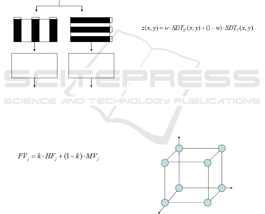
2.3 Image Feature Calculation
Figure 4 shows a block diagram for describing image
feature calculation. It comprises a frame blocking
processing which selects 6 blocks regions from the
inputting image. The size of L (left), C (center) and R
(right) blocks in horizontal direction is W
B
*H and the
size of T (top), C (center) and B (bottom) blocks in
vertical direction is W*H
B
V0
V1
V2
V3
V4
H0
H1
H2
H3
H4
Depth Generation using Structured Depth Templates
327
=∗
=∗
(3)
where W and H mean width and height of the
target image H.
Then for each block, three feature parameters will
be calculated, which include high frequency
component (HF), mean value (MV) and histogram
vales (HV). HF is the sum of edge pixels’ values,
which can be obtained from edge detection. MV is the
average value of all pixels inside of a block. HV is a
matrix of histogram values from 0 to 255, which
describes distribution of pixel values of a block
.
Figure 4: Image feature calculation.
2.4 SDT Estimation
Firstly, the feature value need to calculated, which is
the weighted average of HF and MV by a following
equation
(4)
where j is one of the three block. FV is
corresponding feature value. And k is weight, which
can be set adaptively according to different frames.
Secondly, the feature value should be regularized
through comparing three FVs. We use two
symbols "0" and "1" to indicate minimum and
maximum value respectively.
Thirdly a SDT could be decided. Figure 5 shows
an example of vertical SDT decision based on the
values of 3 parts. The horizontal SDT decision is
same to this.
Based on the method mentioned above, the SDT
can be estimated for each received frame
independently. However, to an video sequence, SDT
estimation is sensitive to camera parameters change
or environment noise. The similar scenes of
successive frames maybe have different SDT. As
result, the flicker will be shown which makes users
uncomfortable. In order to avoid this problem, a SDT
changing detection is used. This is a kind of local
scene change detection, which is not only to enhance
the stability but also to keep the flexibility.
To each block, HF, MV and HV in current frame
and previous frame are compared to decide whether
the scene inside this block is changed or not, i.e. a
new object appearing or the old objects disappearing.
If the scenes in several blocks are changed, SDT
should be estimated for current frame. Otherwise, the
SDTs of current frame are same to them of previous
frame.
The initial depth map is generated by composing
2 SDTs estimated. The equation is as follows
(5)
where z(x,y) is initial depth value of (x,y) point.
is weight for SDT of horizontal direction.
The initial depth map is just showing basic depth
structure that is not enough to describe the image
accurately. So a depth post processing will be used.
As we know, generally if the neighborhood pixels
have similar color or luminance, they belong to a
same object area. So we should set same depth value
to them. Based on this theory, a local bilateral
filtering is presented.
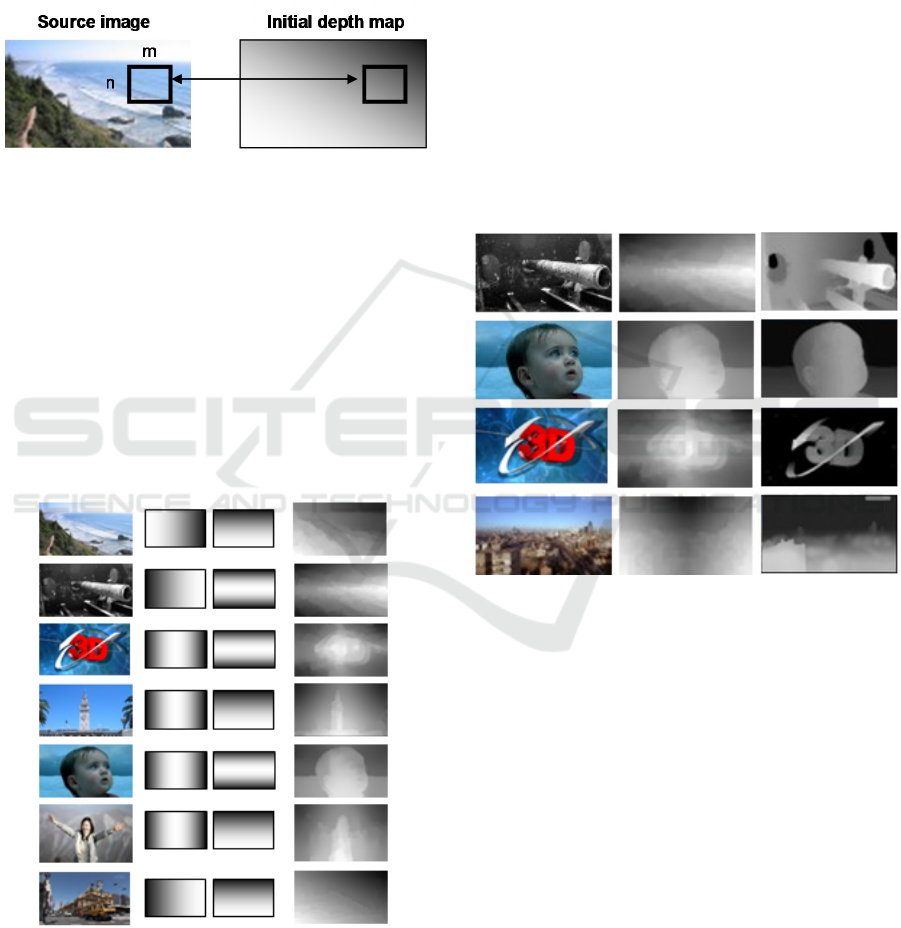
Separating the inputting image and corresponding
initial depth map into several sub-blocks. The size of
each is m*n.
Figure 5: SDT decision rules.
In each sub-block, the bilateral filtering (Tomasi
et al., 1998) is used. The depth values in the initial
depth map will be reset based on the similarity of
L C R
W
B
*H
L C R
W
B
*H
T
C
B
W*H
B
T
C
B
W*H
B
Inputting
image
Feature parameter
calculation
Feature parameter
calculation
3 sets parameters
for 3 horizontal blocks
3 sets parameters
for 3 vertical blocks
w
Bottom_ value
Top_ value
Center_value
1
1
1
0
V3
V1
V4
V4
V0
V1
V2
V0
SIGMAP 2019 - 16th International Conference on Signal Processing and Multimedia Applications
328
pixel values (color or luminance) in the source image.
Figure 6 shows a diagram;
Using median filtering to process the whole depth
map.
By those steps mentioned above, the final depth
amp can be obtained. Comparing to the initial depth
map, the final depth map matches objects accurately,
which can enhance the 3D feeling
Figure 6: Depth map post processing by local bilateral
filtering.
3 EXPERIMENT RESULTS
We used a PC with a 40-inch stereoscopic display
device. In order to evaluate the proposed algorithm,
various images and video sequences with 1280x720
and 1920x1080 resolution were used, including
natural scenes, computer graph scenes, animation
scenes and so on. The weight k for FV calculation is
set to 0.9. The weight w for two SDTs composition is
set to 0.5.
(1) (2) (3)
Figure 7: Simulation results. (1)~(3) shows inputting
image, two-directional SDTs and final depth map
respectively.
Figure 7 shows results of depth maps for 7 test
images. In this figure, the first column shows original
2D images. The central two columns show
corresponding SDTs of two directions. And the last
column shows the final depth maps after depth post
processing.
The simulation results indicate the proposed
method has good performance. It describes the
structure information of each 2D image fully and
correctly. So it makes the final depth map reasonable
to the real scene.
Finally, through comparing ground-true depth
maps and the estimated depth maps generated by two-
directional SDTM, subjective evaluation can be done.
As shown in figure8, the depth ordering and
structures in the estimated depth maps are similar to
them in the original depth maps, which indicate
validity of two-directional SDTM.
Figure 8: Subjective evaluation by comparing original
depth maps genrated manully and generated from two-
directional SDTM.
4 CONCLUSION
In this paper, we developed a new scheme to
automatically achieve 2D to 3D converting. The
proposed method describes the structure feature of the
inputting 2D image by estimating SDTs in two
directions. Then based on SDTs, it achieves
reasonable depth maps which can be verified by the
experimental results. Future works should focus on
improving the performance of the method, such as
adding SDTs in diagonally direction. At the same
time, the proposed method should be combined with
the other depth cues in order to determining the depth
map for more complicated scenes.
Depth Generation using Structured Depth Templates
329

REFERENCES
Harman, P., 2000. Home based 3D entertainment – an
overview. In Proceedings of International Conference
on Image Processing, pages 1-4. IEEE.
Battiato, S., Curti, S., La Cascia, M., Tortora, M., Scordato,
E., 2004. Depth-map generation by image
classification. In Proceedings of Three dimensional
image capture and applications VI, volume 5302. SPIE.
Cheng, C., Li, C., Huang,P., Lin, T., Tsai, Y., Chen, L.,
2009. A block-based 2D-to-3D conversion system with
bilateral filter. In Proceedings of International
Conference on Consumer Electronics, pp.1-2. IEEE.
Moustakas, K., Tzovaras, D., Strintzis, M., 2005.
Stereoscopic video generation based on efficient
layered structure and motion estimation from a
monoscopic image sequence. IEEE Transactions on
Circuits System and Video Technol.., volume 15, pages
1065-1073. IEEE.
Kim, D., Min, D., Sohn, K., 2007. Stereoscopic video
generation method using motion analysis. In
Proceedings of 3DTV Conference, pages 188-197.
IEEE.
Tomasi, C., Manduchi, R., 1998. Bilateral filtering for gray
and color images. In Proceedings of International
Conference on Computer Vision, pages 836–846. IEEE.
SIGMAP 2019 - 16th International Conference on Signal Processing and Multimedia Applications
330
