Quasi-serial Manipulator for Advanced Manufacturing Systems
Bryan Kelly
a
, J. Padayachee
b
and G. Bright
Discipline of Mechanical Engineering, University of KwaZulu-Natal, King George V Avenue, Durban, South Africa
Keywords: Serial, Open Chain, Closed Chain, Parallel, Hybrid, Palletizing, Quasi-serial, Rapid Prototyping, 3D Printing,
Kinematics, Closed Loop Parallelogram.
Abstract: Industrial automation has revolutionised manufacturing and the manufacturing environment. Advanced
manufacturing requires a variety of different robotic manipulators for industrial applications, each with their
defining characteristics. This research paper describes the differences between current industrial
manipulators; it then proposes an open chain hybrid kinematic platform, consisting of closed loop
parallelograms. The application of such a hybrid mechanism is apparent with material handling operations
such as providing solutions for palletizing. A quasi-serial architecture was selected and its corresponding
components were 3D printed. The forward kinematic equations were derived via a geometric approach. The
outputs of these kinematic equations are then validated against empirical results obtained through an
equivalent SolidWorks model of the robot.
1 INTRODUCTION
Modern manufacturing is highly dependent on
industrial automation, specifically for menial tasks
such as repetitive assembly or pick and place
operations, such as packing and unpacking of pallets.
Due to the high number of specialised tasks involved
in these aforementioned procedures, many different
varieties of industrial robots have been researched,
developed and implemented into industry over the
past several decades.
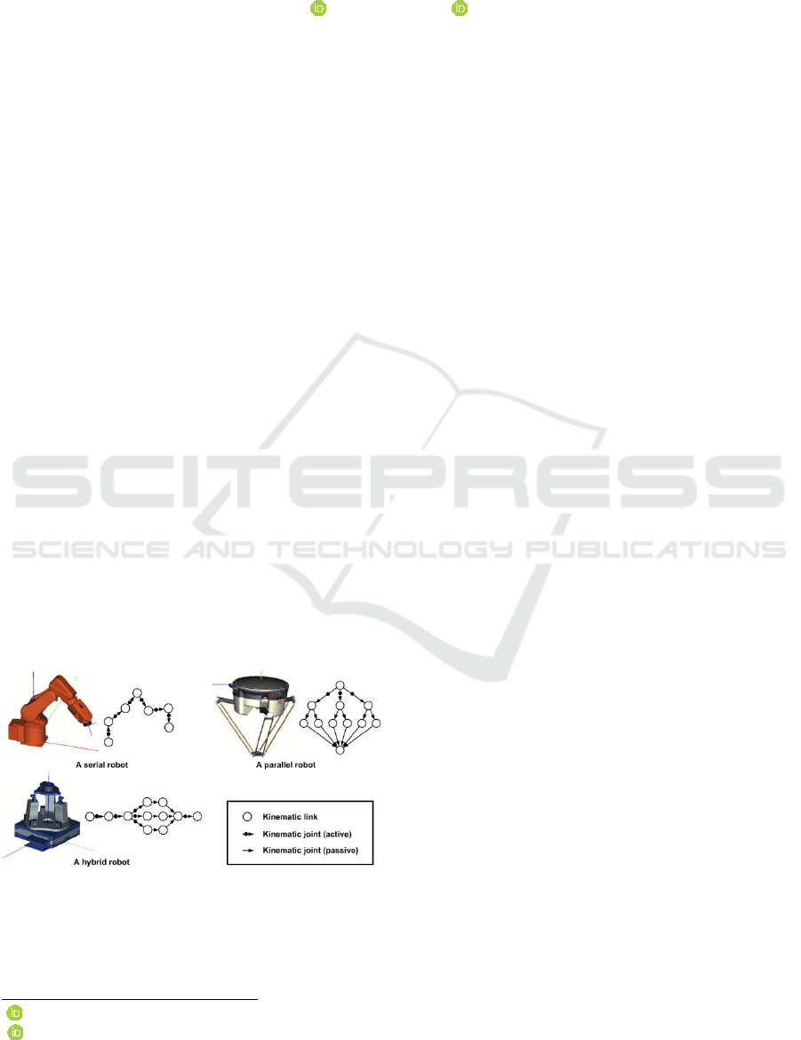
Figure 1: Industrial robot configurations. (Xiao et al., 2014).
Each of these robotic manipulators have vastly
different characteristics and capabilities, depending
a
https://orcid.org/0000-0003-1102-8255
b
https://orcid.org/0000-0003-0358-5289
on their defining geometric characteristics.
(Pandremenos et al., 2011)
There are currently two major classifications of
industrial robotic manipulator geometries, namely
serial and parallel mechanisms. These different forms
of manipulators have been extensively researched and
tested. As a result, the advantages and disadvantages
of said mechanisms are well defined. (Xiao et al.,
2014)
It is now widely accepted that an open kinematic
chain, otherwise known as serial kinematic
manipulators (SKM), are highly articulated and
flexible; however have the drawback of limited
accuracy due to the compounding of errors through
each joint. Serial kinematic manipulator forms
include Cartesian, cylindrical, spherical, SCARA as
well as fully articulated configurations.
(Yeshmukhametov et al., 2017)
Conversely, a closed kinematic chain, or parallel
kinematic manipulator (PKM), is considered to be
rigid, accurate, and have high theoretical dynamic
potential; however have a limited working envelope
due to the configurations inherent lack of flexibility.
PKM architectures come in a huge variety of
geometries. The geometry and symmetries
experienced in the different architectures dictate the
300
Kelly, B., Padayachee, J. and Bright, G.
Quasi-serial Manipulator for Advanced Manufacturing Systems.
DOI: 10.5220/0007839003000305
In Proceedings of the 16th International Conference on Informatics in Control, Automation and Robotics (ICINCO 2019), pages 300-305
ISBN: 978-989-758-380-3
Copyright
c
2019 by SCITEPRESS – Science and Technology Publications, Lda. All rights reserved
overall singularities, which affect the kinematic
equations and control of the mechanism. These
differences allow for great research potential.
(Yeshmukhametov et al., 2017) (Pandilov and
Dukovski, 2012) (Carricato and Parenti-Castelli,
2002)
A combination of closed and open chains into one
configuration may be considered a hybrid kinematic
manipulator (HKM). Ideally, a hybrid mechanism
should have the advantages of both the SKM and
PKM’s.
There are currently several variants hybrid kinematic
mechanisms being researched, however the majority
are of a closed chain configuration. One hybrid
mechanism that has been introduced widely into
industry is that of the palletizing robot. Palletizing
robots are used extensively for handling, moving,
loading, stacking and alike of large geometry and
weight items in industrial applications. These tasks
would otherwise be unsuitable for a human to
perform repeatedly. (Tao et al., 2014)
Although used extensively in industry, there is
minimal literature surrounding the theory and
kinematic modelling of these quasi-serial palletizing
manipulators. The novelty of this research paper
looks to outline some of the fundamental theory and
the initial stages of the kinematic model. The research
also outlines rapid prototyping for testing purposes,
as well as the derivation and validation of the
kinematic equations of a quasi-serial manipulator.
2 QUASI-SERIAL
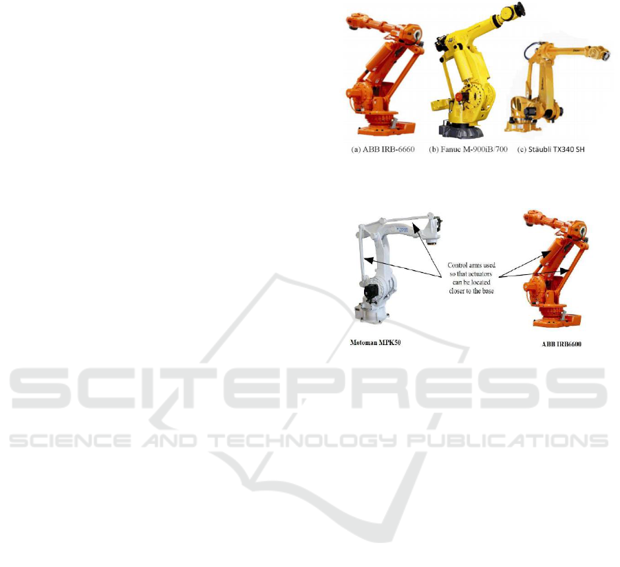
A palletizing robot, illustrated in Figure 2, as
mentioned, is a hybrid mechanism, specifically a
quasi-serial mechanism.
A quasi-serial manipulator is an open kinematic
chain, similar to a SKM, however has one or more
closed kinematic loops within its structure, similar to
a PKM. These closed loop kinematic parallelograms
allow for increased dynamic potential; however, each
closed loop parallelogram will reduce the overall
Degrees of Freedom (DOF). (Shaik et al., 2012) (Sun
and Fang, 2018) (Issa et al., 2017)
A quasi-serial manipulator is able to achieve greater
dynamic potential when compared to a standard open
chain serial manipulator, due to the relocation of mass
lower down, hence decreasing inertial effects as well
as non-linearity’s within the architecture. A quasi-
serial manipulator therefore is more agile than a PKM
and has the ability to carry greater loads compared to
a SKM. The overall footprint of the quasi-serial
mechanism is compact such like a SKM. (Klimchik
et al., 2016) (Klimchik and Pashkevich, 2017)
Figure 2: Industrial palletizing robots. (Klimchik and
Pashkevich, 2017).
Figure 3: Different quasi-serial manipulators. (Shaik et al.,
2012).
Illustrated in Figure 3 are two quasi-serial open chain
manipulators; both containing closed loop
parallelograms, and lowered centre of gravity. All of
the actuation motors are situated co-linear at the base
of the manipulator, allowing movement of the end
effector through a combination of active and passive
joints, similar to that of a closed chain PKM, or four-
bar mechanism.
3 RAPID PROTOTYPING
In order to perform further research and testing, a
physical model was required. Due to the high cost
involved in designing and optimising via several
iterations, it was decided to rapid prototype an
existing quasi-serial architecture.
A design by Florin Tobler named ‘RobotArm’, which
is accessible at Thingyverse.com under the Creative
Commons Licence, was proposed. The design is that
of a three DOF quasi-serial mechanism, illustrated in
Figure 4. (Tobler, 2016)
Rapid prototyping, otherwise known as 3D printing,
was utilised in order to produce the mechanical
components of the RobotArm design. Rapid
prototyping or 3D printing is a new technology based
Quasi-serial Manipulator for Advanced Manufacturing Systems
301
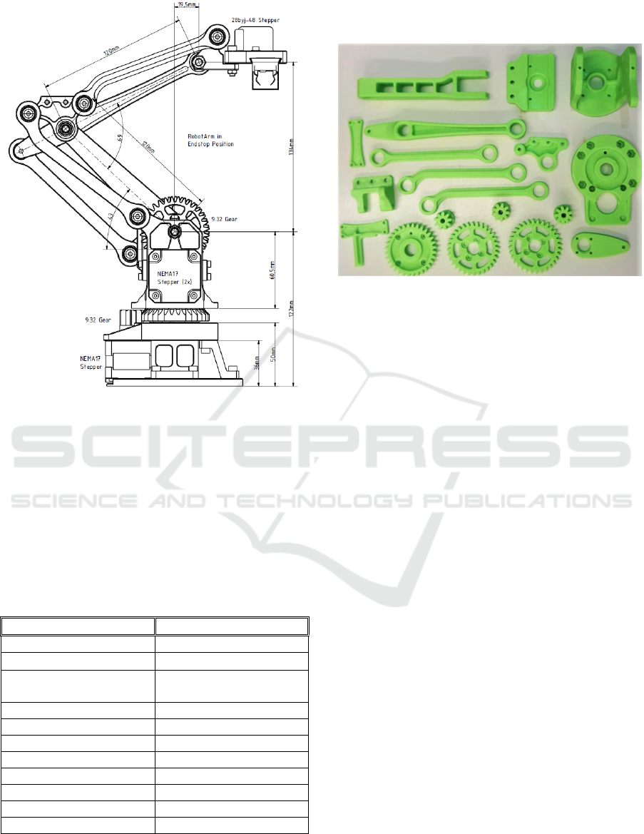
Figure 4: RobotArm by Florin Tobler. (Tobler, 2016).
on additive manufacturing. When compared to
traditional subtractive manufacturing, 3D printing is
much leaner on raw materials. Complex geometries
can be achieved through the additive manufacturing
process.
The parameters outlined in Table 1 were input into
Cura version 3.5.1 which was used to slice the model,
thus creating a G-code required to 3D print the
mechanical components.
Table 1: 3D printing parameters.
PARAMETER
QUANTITY
Material
PLA+
Tensile breaking strength
57.8 MPa
Modulus of elasticity in
flexure
2.3 GPa
Density
1.23-1.25 g/cm3
Layer Height
0.16 mm
Shells
4
Infill
Rectilinear
Infill %
60
Nozzle Temp
215C
Bed Temp
55 C
Print Speed
50 mm/s
As a result, the following components were printed
with approximately 0.2mm tolerance on the overall
dimensional accuracy. This tolerance is due to the
shrinkage of the plastic after cooling.
Figure 5: 3D printed components of RobotArm.
The assembly of the RobotArm required a number of
bearings, nuts, bolts and electronic components.
The hardware utilized for the RobotArm are as
follows:
3 x NEMA 17 Stepper Motors
1 x Servo Motor – end effectors gripper
1 x Arduino Mega 2560 Microcontroller
1 x RAMPS 1.4 Shield
3 x A4988 Stepper Motor Drivers
3 x Mechanical Limit Switches
The mechanical limit switches were not part of the
original design, however, have been introduced in
order to perform a homing sequence. Homing is
required for all CNC machines in order to outline the
working envelope and define a reference point.
This combination of hardware is almost identical to
that of a traditional RepRap 3D printer; hence,
Arduino software will be the base of the control
system.
4 KINEMATICS
Equations that relate geometric properties and joint
positions needed to be derived in order to define the
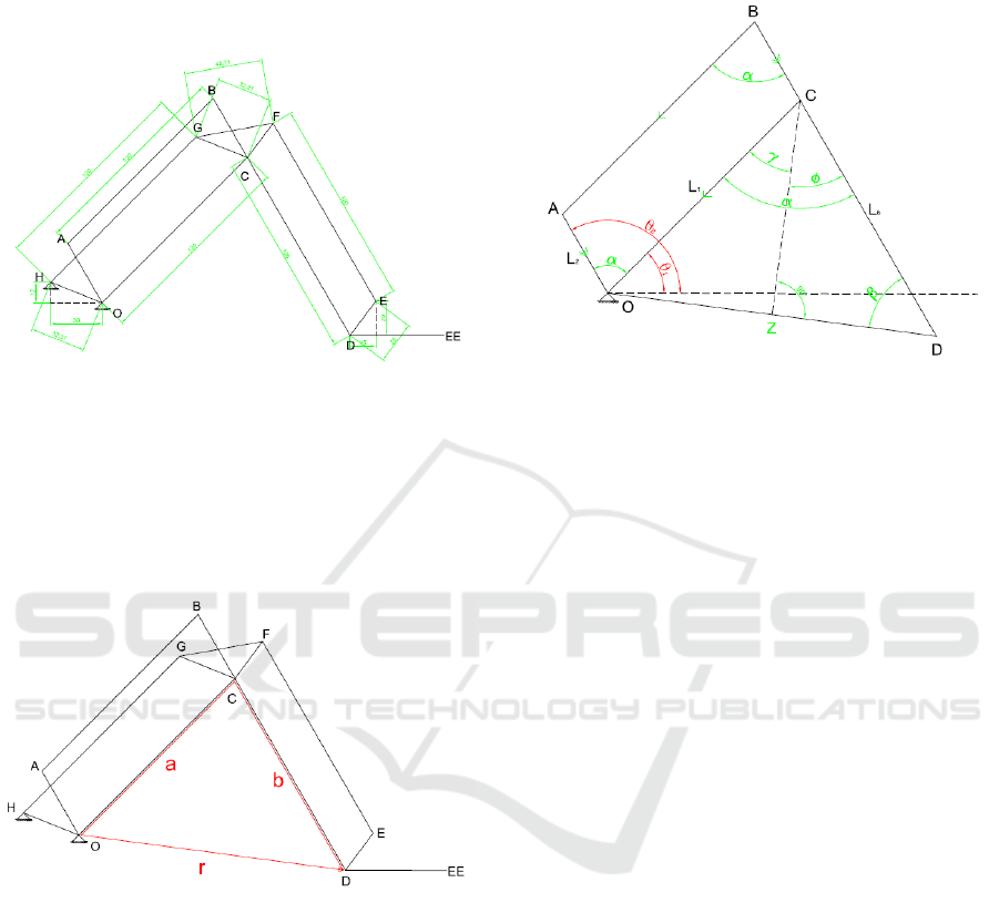
end effectors position in 3D space. Figure 6 illustrates
the physical dimensions and relative joint positions of
the quasi-serial manipulator being researched.
The design of a quasi-serial manipulator consists of
two co-linear actuation joints, namely OA and OC. The
End Effector (point EE) is connected to the Origin
(point O) via three closed loop parallelograms. The
ICINCO 2019 - 16th International Conference on Informatics in Control, Automation and Robotics
302
assignment of joint frames, according the Denavit-
Hartenberg method, becomes difficult and hence a
different approach was selected to solve the kinematic
equations.
Figure 6: RobotArm dimensions.
A closed loop vector can be set up between point O
and point D, on the EE. This vector loop between
points OCD is illustrated in Figure 7. (Liu et al., 2019)
The closed loop vector equation is therefore:
*(1)
Figure 7: Vector loop.
Where is the vector along OC, and
is the vector
along CD. (Liu et al., 2019)
In order to solve vector and
many of the internal
angles needed to be defined. These angles are defined
symbolically in Figure 8.
Hence:
(2)
*(3)
(4)
*(5)
(6)
Figure 8: Vector triangle with angles.
(7)
(8)
*(9)
(10)
(11)
*(12)
(13)
*(14)
This set of equations define the end-effectors position
in 2D planar space, according to two inputs, namely
theta-one (
) and theta-two (
). Where
is the
angle between the x-axis and limb OC, and
is the
angle between the x-axis and OA.
Due to the inherent design of the quasi-serial
manipulator, the end-effector does not change
rotational orientation for any Cartesian coordinate,
henceforth remaining perpendicular to the x-axis.
(Liu et al., 2015)
Using the same graphical approach, the inverse
kinematic equations can be derived.
Quasi-serial Manipulator for Advanced Manufacturing Systems
303
5 TESTING
To ensure that the derived forward kinematic
equations, outlined in Section 4, were defining the
end-effectors position correctly in 2D planar space;
tests between the physical model and the kinematic
equations needed to be performed. Initially a
graphical test approach was adopted, and
subsequently an analytical approach. The results of
each test sample can then be compared for offset error.
In order to achieve sound experimental data, it was
vital to produce several accurate graphical
representations of the quasi-serial manipulator in
different poses and end-effector positions. Therefore,
the links were modelled on SolidWorks in accordance
with the provided geometries of the RobotArm. The
links were then mated with the introduction of mate
joint limits. The mate limits are in accordance with
the physical and geometrical limits of the RobotArm.
Making
(actuates link OC) and
(actuates link
OA) random angles within the mate limit controller,
and subsequently measuring from point O to point D,
SolidWorks provides a value for dX and dY. This
empirical x and y value can then be compared to an
analytical result.
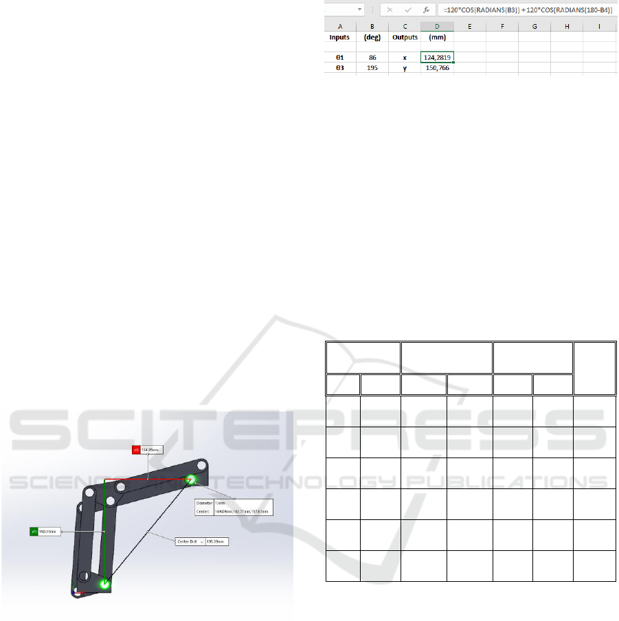
Figure 9: Graphical testing via SolidWorks.
Figure 9 illustrates the graphical result for an input of
and
.
In order to produce several analytical results
accurately, an Excel spreadsheet was set up with two
inputs and two outputs linked through the kinematic
equations from Equation 14. It was necessary to
convert the input angles from degrees into radians for
the Excel calculation. The output is an x and y
coordinate value of point D, comparable to the results
from the graphical approach.
Figure 10 is a snapshot of the Excel spreadsheet used.
It illustrates the results of the derived kinematic
Figure 10: Analytical testing via Excel spreadsheet.
equations from the same inputs as Figure 9.
This procedure was repeated for several different
and
inputs. The results of both the empirical and
analytical tests, for each different end effectors
positions, are represented in Table 2 for comparison.
It can be seen from Table 2 that the results correlate
extremely closely, with less than 0.1% difference
between the measured empirical position and the
calculated analytical position. This result implies that
the forward kinematic equations derived in Section 4
are accurately describing the end-effectors position in
2D planar space.
Table 1: Empirical vs analytical results.
6 CONCLUSIONS
The paper described the major classifications of
current industrial robots, namely serial and parallel
mechanisms, ie SKM and PKM. The concept of a
hybrid robot was then introduced with the hypothesis
that a hybrid mechanism would have the advantages
of both the serial and the parallel architectures.
Theory and current examples of hybrid mechanisms
were outlined briefly followed by the concept of a
hybrid open chain manipulator, or quasi-serial
manipulator. Quasi-serial manipulators have begun to
be prominent for material handling operations.
The selection of a current quasi-serial manipulator
was made in order to perform further research and
Inputs
(degrees)
Empirical
(mm)
Analytical
(mm)
Erro
r
(%)
x
y
x
y
86
195
124.2
8
150.7
7
124.
3
150.
8
-
0.018
74.
5
175.
5
151.7
106.2
2
151.
7
106.
2
0.006
64
152
158.5
6
51.52
158.
6
51.5
-
0.019
43
125
156.5
9
-
16.46
156.
6
-
16.5
-
0.004
22
103
138.2
6
-
71.97
138.
3
-
71.9
-
0.076
10
70
77.13
-
91.93
77.1
-
91.9
0.035
ICINCO 2019 - 16th International Conference on Informatics in Control, Automation and Robotics
304

validation. This quasi-serial RobotArm desktop
model was subsequently rapid prototyped via 3D
printing. The parameters input into Cura for slicing of
the model have been outlined in Section 3.
The kinematic model was then derived for 2D planar
space via a closed loop vector method. These
kinematic equations needed to be validated and hence
an empirical versus analytical test approach was
implemented. The graphical empirical results were
obtained with the use of an equivalent SolidWorks
model of the physical RobotArm geometry. The
analytical results were obtained via the forward
kinematic equations outlined in Section 4. The results
were then tabulated in Section 5 and subsequently
compared. The results correlated extremely closely
well with a maximum error of less than 0.02%.
Future work looks to define the inverse kinematic
equations, develop a 3D workspace for a single
RobotArm, including singularities and non-
linearities. Further is to then introduce several of
these RobotArms into the same workspace for
collaborative applications. A Graphical User
Interface (GUI) will be developed in order to control
and monitor the final platform.
REFERENCES
Carricato, M. & Parenti-Castelli, V. 2002. Singularity-Free
Fully-Isotropic Translational Parallel Mechanisms. The
International Journal of Robotics Research, 21, 161-
174.
Issa, A., Aqel, M. O. A., Albelbeisi, M. M., , M. O. &
Mortaja, M. A. Palletizing Manipulator Design and
Control Using Arduino and MATLAB. 2017
International Conference on Promising Electronic
Technologies (ICPET), 16-17 Oct. 2017 2017. 60-65.
Klimchik, A., Magid, E., Caro, S., Waiyakan, K. &
Pashkevich, A. Stiffness of serial and quasi-serial
manipulators: comparison analysis. MATEC Web of
Conferences, 2016. EDP Sciences, 02003.
Klimchik, A. & Pashkevich, A. 2017. Serial vs. quasi-serial
manipulators: Comparison analysis of elasto-static
behaviors. Mechanism and Machine Theory, 107, 46-
70.
Liu, X.-J., Li, J. & Zhou, Y. 2015. Kinematic optimal
design of a 2-degree-of-freedom 3-parallelogram planar
parallel manipulator. Mechanism and Machine Theory,
87, 1-17.
Liu, Z., Wu, J. & Wang, D. 2019. An engineering-oriented
motion accuracy fluctuation suppression method of a
hybrid spray-painting robot considering dynamics.
Mechanism and Machine Theory, 131, 62-74.
Pandilov, Z. & Dukovski, V. 2012. Parallel kinematics
machine tools: Overview-from history to the future.
Annals of the Faculty of Engineering Hunedoara, 10,
111.
Pandremenos, J., Doukas, C., Stavropoulos, P. &
CHRYSSOLOURIS, G. 2011. Machining with robots:
a critical review. Proceedings of DET2011, 1-9.
Shaik, A. A., Tlale, N. S. & Bright, G. 2012. A new hybrid
machine design for a 6 DOF industrial robot arm.
Sun, L. & Fang, L. 2018. An approximation method for
stiffness calculation of robotic arms with hybrid open-
and closed-loop kinematic chains. Advances in
Mechanical Engineering, 10, 1687814018761297.
Tao, Y., Chen, F. & Xiong, H. 2014. Kinematics and
Workspace of a 4-DOF Hybrid Palletizing Robot.
Advances in Mechanical Engineering, 6, 125973.
Tobler, F. 2016. RobotArm [Online]. Thingyverse.com.
Available:
https://www.thingiverse.com/thing:1718984 [Accessed
15/9/2018 2018].
Xiao, W., Huan, J. & Dong, S. 2014. A STEP-compliant
Industrial Robot Data Model for robot off-line
programming systems. Robotics and Computer-
Integrated Manufacturing, 30, 114-123.
Yeshmukhametov, A., Kalimoldayev, M., Mamyrbayev, O.
& Amirgaliev, Y. Design and kinematics of
serial/parallel hybrid robot. Control, Automation and
Robotics (ICCAR), 2017 3rd International Conference
on, 2017. IEEE, 162-165.
Quasi-serial Manipulator for Advanced Manufacturing Systems
305
