
The Influence of the Level of the Flow Path Blockage at the Inlet on
the Fan Characteristics
Grigorii Popov, Oleg Baturin, Andrei Volkov, Daria Kolmakova, Vasilii Zubanov,
Anastasia Korneeva and Yulia Novikova
Samara National Research University, Samara, Russia
Keywords: Nonuniformity, Fan, Turbofan Engine, Low Pressure Spool.
Abstract: The paper presents the results of numerical simulation of the effect of flow nonuniformities at the engine inlet
on the working process of the engine fan. Flow nonuniformities is created by pushing the interceptor into the
flow part of inlet device like as it is often done during field tests. The authors have created a numerical model
capable of considering non-stationary processes in the fan using nonlinear harmonic analysis. As a result,
qualitative and quantitative estimates were obtained of the influence of overlapping of the inlet duct by the
interceptor on the main parameters of the fan workflow. It is shown that the more the duct is blocked, the
more its parameters are deteriorated. Moreover, the deterioration is not linear, but according to the dependence
of the 2nd order.
NOMENCLATURE
G mass flow rate of the working fluid, kg/s;
p* total pressure, Pa;
Т* total temperature, K;
n rotor speed, %;
m bypass ratio;
efficiency;
Y+ non-dimensional wall distance;
flow angle, degree;
LPC low pressure compressor;
RW rotor wheel;
GV guide vane;
NLH nonlinear harmonic analysis.
Note. The flow angles in this research are measured
from the aerofoil cascade front.
1 INTRODUCTION
Inlet devices of bypass turbofan engines (characterized
by a high degree of bypass ratio) of modern passenger
aircraft have a large flow area and are relatively short
(their length is less than the diameter). It would seem
that losses in such conditions should be minimal in all
typical flight conditions. However, in some cases (for
example, with a strong side wind, flying sideways, etc.)
a separation flow occurs at the inlet edge of the air
intake, which causes the flow at the fan inlet to become
uneven. This, in turn, causes a significant reduction in
the efficiency of the low-pressure compressor and the
engine. In addition, the inlet nonuniformity causes
oscillations of the fan blades, which can lead to their
destruction.
For a long time, the study of the influence of inlet
nonuniformity on the GTE workflow was carried out
during field tests with an aircraft air intake or its
simulator (Figure 1). The latter is a complex of
resistances (grids, plates, struts), located between the
lemniscate attachment and the engine, creating the
same uneven velocity field at the fan inlet, as the
aircraft air intake on the flight mode of interest
(Grigor'ev, 2009).
At present, in connection with the development of
numerical methods for modelling gas-dynamic
processes and strength calculations, it has become
possible to model the influence of the inlet
nonuniformity on the workflow of the fan and the
engine. This will allow an assessment of the influence
of nonuniformity at the stage of calculations, without
manufacturing many prototypes. As a result, at the
initial design stage, the design variants that do not
work satisfactorily under the specified conditions will
be eliminated, which will significantly reduce the
time and cost of engine development.
In this paper, the authors aim to test the possibility
Popov, G., Baturin, O., Volkov, A., Kolmakova, D., Zubanov, V., Korneeva, A. and Novikova, Y.
The Influence of the Level of the Flow Path Blockage at the Inlet on the Fan Characteristics.
DOI: 10.5220/0007836502470254
In Proceedings of the 9th International Conference on Simulation and Modeling Methodologies, Technologies and Applications (SIMULTECH 2019), pages 247-254
ISBN: 978-989-758-381-0
Copyright
c
2019 by SCITEPRESS – Science and Technology Publications, Lda. All rights reserved
247
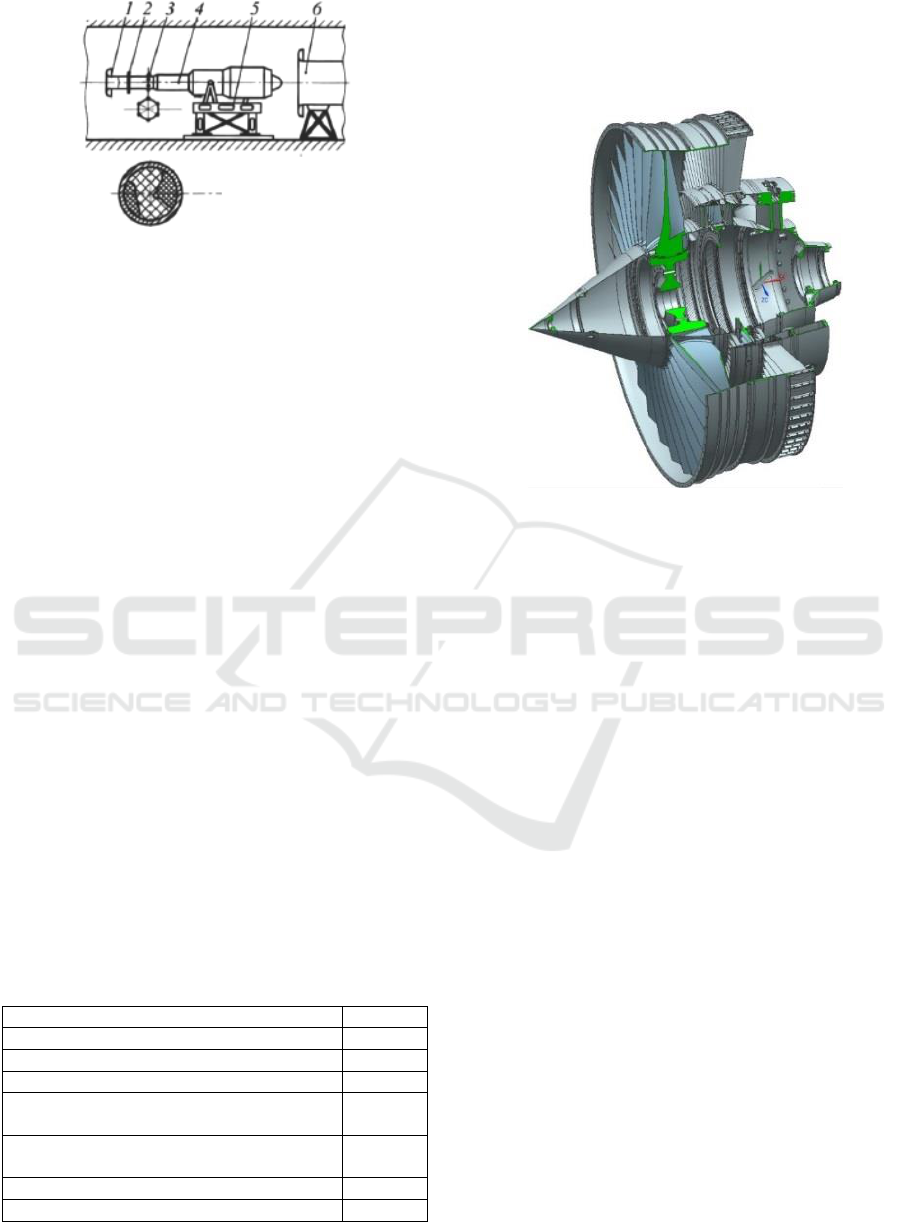
1 - lemniscate tip; 2 - simulator; 3 - instruments controlling
the flow irregularity; 4 - the engine; 5 - thrust measuring
device; 6 - ejector tube
Figure 1: Engine test system with an inlet nonuniformity
simulator (Grigor'ev, 2009).
of conducting a computational study of the influence
of the inlet nonuniformity on the working process
(efficiency) of a fan of turbofan engine, reproducing
tests with an input simulator. There will also be given
a qualitative and quantitative assessment of the
influence of the inlet nonuniformity on the main
parameters of the working process of the engine fan.
2 TEST OBJECT
The object of the study was the fan of the NK-56
turbojet engine, developed at Kuznetsov, PJSC
(Samara, Russia) (JSC "Kuznetsov", 2019) for civil
aviation aircraft in the early 1980s, but not
commercialized. The main parameters of the NK-56
engine are given in Table 1 (Zrelov, 2002).
The appearance of the investigated fan is
presented in Figure 3. The number of blades is 30.
Information about the geometry of the fan and some
of its test results (in the form of internal reports of the
company) was transferred by Kuznetsov, PJSC to
Samara National Research University (Samara
University, 2019) s part of joint research.
Table 1: The main parameters of the NK-56 engine (Zrelov,
2002).
Thrust, kN
177
Pressure ratio
25.5
Gas temperature before the turbine, K
1571
Bypass ratio
4.8
Specific fuel consumption (M = 0, H = 0),
kg/N h
39.1
Specific fuel consumption (M = 0.8, N = 11
km), kg/kN h
63.75
Outer diameter, m
2.05
Weight with reverse, kg
3340
To conduct the research, a computational model
of the LPC of the NK-56 engine was created using the
Numeca FineTurbo software (NUMECA, 2008),
which includes a fan with an add stage.
Figure 2: Fan of the NK-56 engine.
Spalart-Allmaras and k-epsilon turbulence
models were used in the calculations.
The geometry of the computational domain was
created in accordance with the drawings submitted by
PJSC Kuznetsov. The computational area included
the inlet section, the rotor (RW) and the fan guide
vanes (GV), the bypass section and the second stage
of the LPC with the engine annular frame (Figure 3).
In constructing the model, the deformation of the
working blades from the forces acting on them was
considered. For this purpose, a preliminary
calculation of the fan workflow was carried out at a
rotor speed of 100%. Obtained gas loads acting on the
blades, were transferred to the ANSYS Mechanical.
It identified the deformation of the aerofoil, arising
under the action of centrifugal load and gas forces.
Then, information on the geometry of the deformed
aerofoil was transferred to the Numeca FineTurbo to
clarify the gas loads. In total, four such iterations were
performed. The criterion for the convergence of
iterations was the absence of a change in more than
1% of the deformed shape of the blade aerofoil during
the subsequent iteration.
The appearance of the resulting computational
model is shown in Figure 3.
The values of the total pressure p
*
=101325 Pa and
the total temperature T
*
=288.15 K were set as the
boundary conditions at the inlet to the computational
domain. The flow rate of the working fluid was set at
the outlet from each circuit. The ratio of mass flow
ratios at the outlet from each circuit advised the
SIMULTECH 2019 - 9th International Conference on Simulation and Modeling Methodologies, Technologies and Applications
248
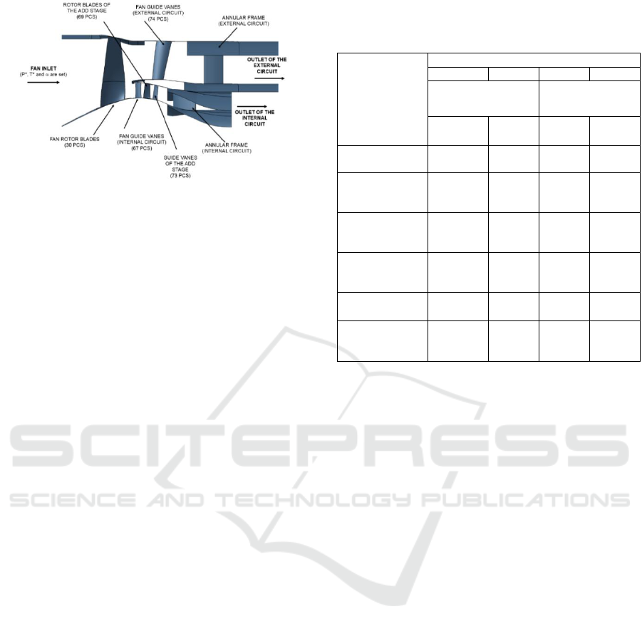
Figure 3: Appearance of the design model of the fan with
add stages.
required bypass ratio (for the rotor speed n = 95% -
m = 4.9; for n = 100% - m = 4.8; for n = 105% -
m = 4.7).
Two mesh models were created for the
computational model: light (in total, 2.36 million final
volumes - Y+ is more than 7) and heavy (7.06 million
final volumes, Y + is more than 2).
4 VERIFICATION OF THE
COMPUTATIONAL MODEL
At the first stage of the study, the adequacy
assessment and validation of the created
computational model was carried out. For this, the
calculated characteristics obtained using various
stationary models differing in the turbulence model
and density of the finite volume mesh were compared
with the test results on the engine test bench provided
by Kuznetsov, PJSC. Due to the large time that has
passed since the tests, a detailed description of the
experimental setup and the error estimates of the test
data were not provided.
A total of 4 different computational models were
created:
No. 1 — Spalart-Allmaras (SA) turbulence model,
the number of final volumes is 2.36 million;
No. 2 — k-epsilon turbulence model, the number of
final volumes is 2.36 million;
No. 3 — Spalart-Allmaras (SA) turbulence model,
the number of final volumes is 7.06 million;
No. 4 — k-epsilon model of turbulence, the number
of final volumes is 7.06 million.
Comparison of the results obtained as a result of
stationary calculation with experimental data is
shown in Figures 4 and 5 and in Table 2.
Table 2: Comparison of the results of calculations obtained
using the considered numerical models with the data by
PJSC "Kuznetsov".
The deviation
of calculations
by the
numerical
model relatively
data by PJSC
"Kuznetsov"
Model No.
1
2
3
4
mesh 2.36 mln.
mesh 7.06 mln.
SA
k-ε
SA
k-ε
Internal circuit
efficiency
0.5...2%
more
0...1%
more
1.5%
more
1...3%
more
External circuit
efficiency
3...6%
more
3...6%
more
2%
more
1.5...5
%
more
Mass flow rate
of the internal
circuit
6% less
4%
less
2%
3%
less
Mass flow rate
of the external
circuit
2%
2%
2%
2%
𝜋
𝑐
∗
of the
internal circuit
Higher
by 0.05
by
0.03
Coinci
des
by
0.02
𝜋
𝑐
∗
of the
external circuit
by
0.07...
0.13
by
0.05...
0.12
by
0.02
by
0.03...
0.1
Analysing the data presented in Figures 4...5 and
Table 2, we can come to the following conclusions:
none of the created computational models show
complete agreement with the experimental
characteristics in the whole considered range of
parameters;
all computational models show significantly
overestimated values of the pressure ratio in the
external circuit, but at the same time, they well
predict the characteristics of the internal circuit;
all computational models show overestimated
efficiency values, especially in the external circuit
(the difference reaches 6%);
the value of the working fluid mass flow rate, at
which the maximum efficiency is achieved, for
the external circuit is in good agreement with the
data of the design calculation, while for the
internal circuit, the resulting flow rate is usually
underestimated by 2...4%;
the smallest discrepancy for the external circuit is
observed at a high rotor speed (n = 105%), and for
the internal circuit - at the small (n = 95%);
considering the real deformation of the blade with
the help of coupled simulation of strength and gas
dynamics allows to reduce the quantitative
discrepancy between the calculation data and
design data. Qualitatively, the nature of the
calculated characteristics of the LPT does not
change.
The Influence of the Level of the Flow Path Blockage at the Inlet on the Fan Characteristics
249
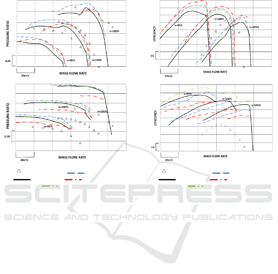
a) For external circuit
b) For internal circuit
- experimental data; - model No.1;
- model No.2; - - model No.3;
- model No.4
Figure 4: Comparison of the pressure characteristics
obtained using the created computational models with
experimental data.
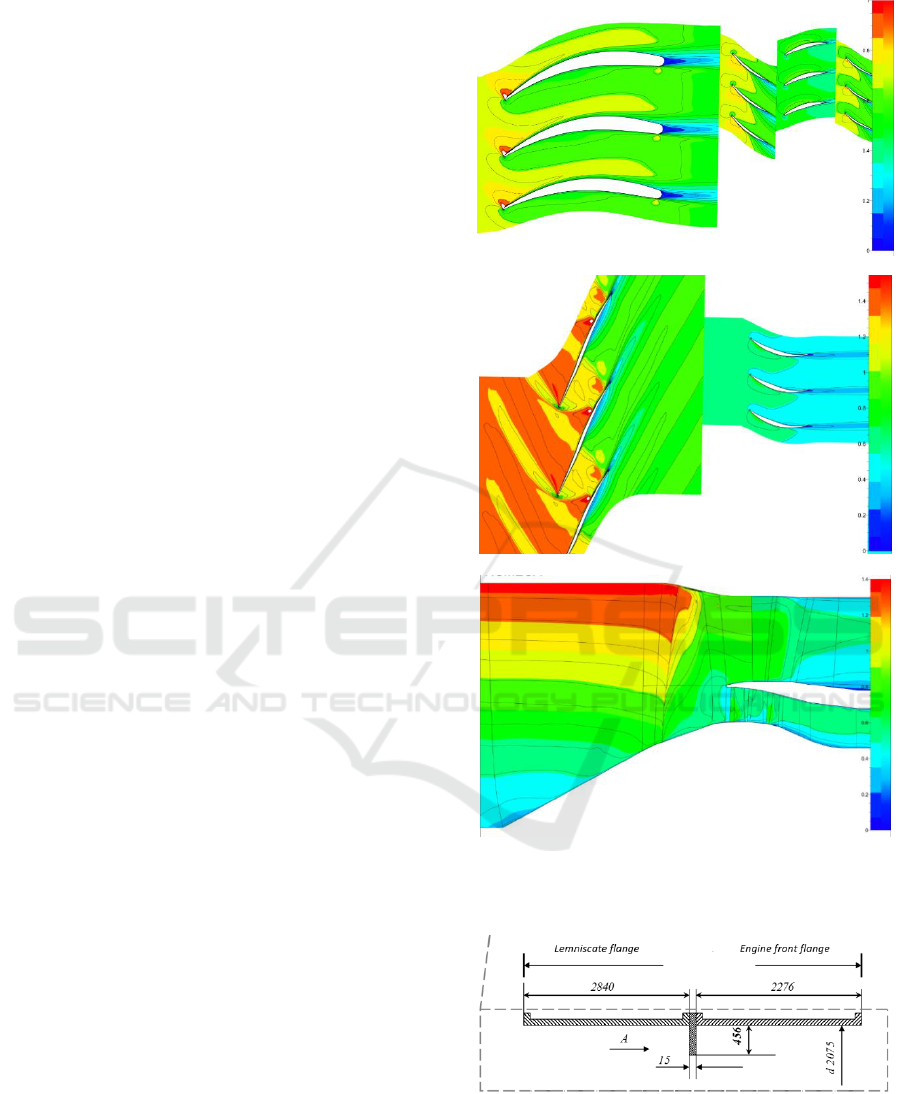
Of all the models considered, the best match with
the data of the design calculation is shown by model
No. 3 (fine mesh and Spalart-Allmaras turbulence
model). It is accepted as the final for further research
of the workflow in the fan blade passages. The Mach
number contours obtained using this model are shown
in Figure 6.
5 UNSTEAY (NLH)
COMPUTATIONAL MODEL
At the second stage of the study, based on the created
and verified computational model of the workflow of
the LPC of the NK-56 engine, a computational model
was created to study the influence of the inlet
nonuniformity on the working process of its fan.
The modified model was created in such a way as to
meet the conditions of testing a fan with a simulator
of the inlet nonuniformity on the test benches of PJSC
Kuznetsov. There, the nonuniformity is modelled by
extending the interceptor into the duct between the
lemniscate and the inlet to the fan (Figure 7). During
a) For external circuit
b) For internal circuit
- experimental data; - model No.1;
- model No.2; - - model No.3;
- model No.4
Figure 5: Comparison of the efficiency characteristics
obtained using the created computational models with
experimental data.
the tests, the intensity of the inlet nonuniformity was
regulated by the depth of the interceptor extension to
the flow part of the duct.
Due to the highly variable nature of the flow at the
fan inlet, the task should be solved in a transient
statement. In this case, since the nonuniformity
generated by the interceptor has a different intensity
of direction of the velocity vectors around the
circumference of the RW, the assumption about the
periodicity of the flow cannot be accepted, and the
computational model must contain all the blade
passages.
The solution to the problem of studying the
influence of inlet nonuniformity on the workflow of
the LPC using a transient simulation of a full circle
SIMULTECH 2019 - 9th International Conference on Simulation and Modeling Methodologies, Technologies and Applications
250
model (containing all passages of LPC of the turbofan
engine) requires exorbitant computer resources, and
cannot be successfully done in a reasonable time
using available computer equipment. For this reason,
it was assumed to conduct the research using the
method of nonlinear harmonic analysis (NLH)
(Vilmin et al., 2013), which allows to obtain
nonstationary flow patterns several times faster than
using transient simulation. The method allows to
obtain non-stationary flow fields by means of
decomposition of periodic oscillations in Fourier
based on a preselected number of harmonics, usually
associated with the transmission frequencies of the
blades of the turbomachine configuration and their
multiples. At the same time, only one blade passage
is required for analysis. This approach allows to
obtain pictures of dynamic processes by 2 orders of
magnitude faster than with transient calculation
(NUMECA International The Nonlinear Harmonic
module, 2019).
The number of harmonics used in nonlinear
harmonic analysis is 3. A series of calculations was
also carried out with the number of harmonics equal
to 7. The results obtained differed little from the data
obtained with 3 harmonics, but in the case of 7
harmonics the solution process was significantly less
stable.
The NLH method could not be applied to the
required number of blade rows and when the
compressor was operating simultaneously for 2
circuits. For this reason, the geometry of the LPC was
significantly simplified: the separator of the contours
was eliminated (the task became single-circuit). The
computational domain contained only a RW and a
model GV (“lengthened up” GV of the fan of the
internal circuit) (Figure 7) simulating the effect of
downstream elements on the rotor.
An input section imitating the engine inlet channel
with an interceptor was attached to the inlet boundary
of the fan domain (Figure 8). Its geometry was
created in the Numeca IGG software. Several variants
of its geometry were created, differing in the length
by which the interceptor was extended. The total
number of finite volumes of the computational model
shown in Figure 9 is 4 mln. The mesh models of the
RW and GV domains were made with the settings
corresponding to the Model No. 3 of the LPC (see
above).
Hub section of the fan
Shroud section of the fan
The averaged values in the meridional section
Figure 6: Contours of Mach numbers in relative motion in
the fan at the operating point at n = 100%.
Figure 7: Geometry of the simulated variant of the
interceptor in the inlet device when testing the NK-56
engine.
The Influence of the Level of the Flow Path Blockage at the Inlet on the Fan Characteristics
251
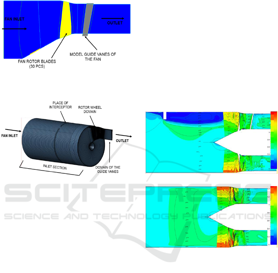
Figure 8: Simplified geometry of the NK-56 engine fan for
conducting research on the effect of inlet nonuniformity on
its workflow.
Figure 9: Computational model for studying the influence
of inlet nonuniformity on the fan workflow.
6 DISCUSSION OF THE RESULTS
Figure 10 shows the contours of Mach numbers in
relative motion when the interceptor extends into the
flow part so that it covers 6.8% of the flow part of the
duct, in two mutually perpendicular planes passing
through the engine axis. It shows that in front of the
interceptor a zone of flow deceleration is formed, and
behind it a developed separation zone reaches the
inlet of the engine, located at a distance more than the
size of its outer diameter (i.e. by more than one
calibre). In this case, part of the flow entering the duct
opposite the interceptor is redirected to the axis of the
engine, causing local flow acceleration, and changing
the flow structure there. That is, the injecting the
interceptor affects not only the structure immediately
near it, but the rest of the duct to a depth of more than
half the diameter of the engine.
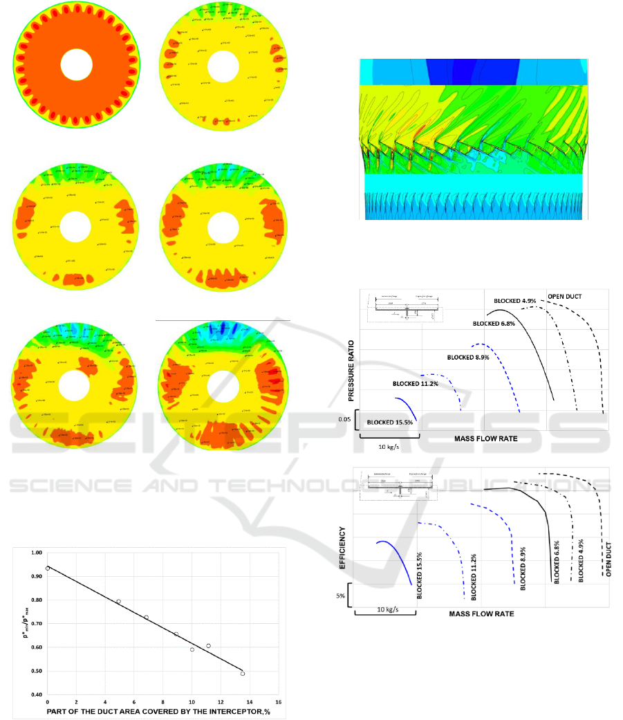
These circumstances lead to the emergence of
significant inhomogeneity over the cross section of
the pressure field at the fan inlet (Figure 11). It can be
seen that it is formed behind the interceptor, and, with
an increase of the interceptor extension, an area of
reduced total pressure grows behind it. In this case,
Figure 11 confirms that with an increase in the
overlapping area of the duct, the uniformity of the
pressure field is disturbed over the entire cross
section. And the higher the extension, the greater the
level of unevenness.
The result of a quantitative assessment of the
effect of the interceptor extension level on the
nonuniformity of the pressure field is shown in Figure
12. There, the criterion of non-uniformity applies a
value equal to the ratio of the minimum total pressure
in the cross section to its maximum value. The
smaller this value, the greater the uneven flow. As can
be seen from Figure 12, the flow nonuniformity with
increasing overlap of the flow path by the interceptor
increases linearly. Moreover, when 13% overlap, the
nonuniformity reaches 50%.
a) Section plane No.1 passing through the axis of the
engine perpendicular to the interceptor
b) Section plane No.2 passing through the axis of the
engine perpendicular to plane No. 1
Figure 10: The calculated contours of the change in the
Mach number in relative motion in the “inlet duct+ fan”
system when the interceptor is extended so that it blocks
6.8% of the flow-part of the duct.
The above-described phenomena lead to the fact
that the conditions at the inlet to each blade passage
and, correspondingly, the flow structure there are
unique (Figure 13), disrupting the interaction of
adjacent passages and reducing the pressure ratio,
efficiency, stability margins and air flow through the
fan.
The effect of nonuniformity on the fan workflow
parameters at a rotation frequency of n = 100% can
be estimated from the evolution of the characteristics
as the inlet device is overlapped by the interceptor
(Figure 14). It can be seen from the above data that
SIMULTECH 2019 - 9th International Conference on Simulation and Modeling Methodologies, Technologies and Applications
252
a) No interceptor
b) Interceptor overlaps
4,9% of passage area
c) Interceptor overlaps
6,8% of passage area
d) Interceptor overlaps
8,9% of passage area
e) Interceptor overlaps
11.2% of passage area
f) Interceptor overlaps
13,5% of passage area
Figure 11: Transformation of the total pressure fields at the
fan inlet flange at different levels of extension of the
interceptor (at the top) to the flow part of the supply duct.
Figure 12: Influence of the overlap level of the input duct
by the interceptor on the unevenness of the total pressure
field at the fan inlet.
with the increase in the part of the duct blocked by the
interceptor, all compressor parameters deteriorate:
the working fluid mass flow rate, the pressure ratio,
and the efficiency decrease. In addition, the range of
mass flow rate between the modes of surge and choke
is also reduced, pressure lines become more vertical.
This signals a decrease in the stability of the
compressor.
Figure 13: Contours of Mach numbers in relative motion in
the peripheral part of the fan (height of 98%) opposite the
installation site of the interceptor.
Pressure characteristics
Efficiency characteristics
Figure 14: Comparison of fan characteristics at n = 100% at
different values of the interceptor extension into the flow
part.
A quantitative assessment of the influence of the
overlap of the flow part of the input duct on the
parameters of the compressor workflow, obtained
from the analysis of Figure 14, is shown in Figure 15.
As can be seen, the increase in the level of the
interceptor extension degrades the parameters not
linearly, but by parabolic dependence. The least
change is in the mass flow rate of the working fluid
(with a decrease in the area of the inlet duct by 10%,
it is reduced by 3%). The difference between the
The Influence of the Level of the Flow Path Blockage at the Inlet on the Fan Characteristics
253
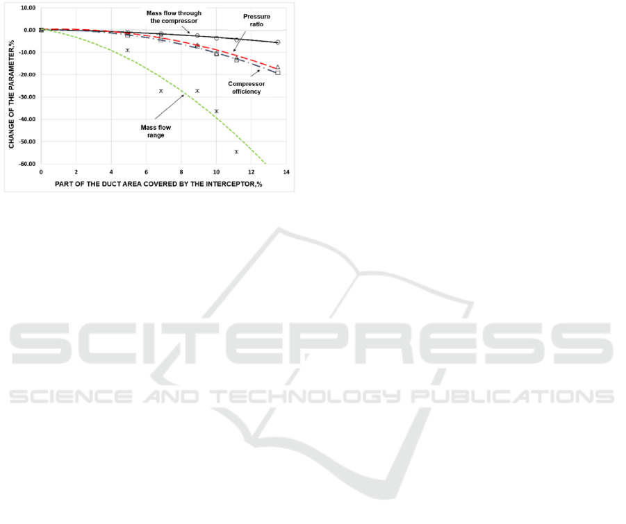
values of mass flow rate at surge and choke changes
most of all (with a decrease in the duct area by 10%,
it is reduced by 40%). If the duct area is reduced by
10%, the efficiency of the compressor decreases by
11% (rel.), and the pressure ratio - by 9%.
Figure 15: Changing the main parameters of the compressor
process at different levels of overlapping the inlet section.
7 CONCLUSIONS
As a result of the performed work, the complex
scientific and technical problem of a reliable
computational study of the influence of the inlet
nonuniformity on the working process of a fan of a
turbojet bypass engine was solved. The solution to
this problem is hampered by the fact that the process
under study is transient and leads to the fact that
different fan blade passages operate in different
conditions. Such a problem should be solved in a
transient setting using a full circle model. However,
such a computational model, in addition to the
enormous calculation time inherent in transient
problems, contains the number of finite elements in
the hundreds of millions, which, due to the limited
possibilities of the computer equipment, is
unacceptable for the authors of the paper.
To solve this problem, the authors developed and
verified a numerical computational model of the
workflow of an inlet device, retractable interceptor
(an inlet nonuniformity generator) and a turbofan fan
stage using NLH approach.
In the future, the results are planned to be
transferred to the module of the strength calculation
and to evaluate the effect of inlet nonuniformity on
the static and dynamic loads on the fan blades.
ACKNOWLEDGEMENTS
This work was supported by the Russian Federation
President's grant (project code МК-3168.2019.8).
REFERENCES
Grigor'ev, V.A., 2009. Ispytaniya aviatsionnykh dvigatelej
(Aircraft engine testing). Mashinostroenie, Moskow.
JSC "Kuznetsov", 2019. Accessed January 10.
http://www.kuznetsov-motors.ru/en.
NUMECA, 2008. User Manual AutoGrid5 Release 8.4,
NUMECA.inc., Belgium.
NUMECA International The Nonlinear Harmonic module,
2019. Accessed January 10.
https://www.numeca.com/product/nlhmethod.
Samara University, 2019. Accessed January 10.
https://ssau.ru/english/.
Venediktov, V.D., Granovsky, A.V., 1990. Atlas
eksperimental'nykh kharakteristik ploskikh reshetok
okhlazhdaemykh gazovykh turbin (The Atlas of
Experimental Performances of Cooled Gas Turbine
Blade Cascades), CIAM.
Vilmin, S., Lorrain, É.,Tartinville, B., Capron, A. and
Hirsch, Ch., 2013. The nonlinear harmonic method:
from single stage to multi-row effects Int J of
Computational Fluid Dynamics 27(2): 88-99.
Zrelov, V.A., 2002. Otechestvennye GTD. Osnovnye
parametry i konstruktivnye skhemy. CHast' 2
(Domestic GTE. Key parameters and design schemes.
Part 2). SGAU, Samara.
SIMULTECH 2019 - 9th International Conference on Simulation and Modeling Methodologies, Technologies and Applications
254
