Modeling and Analysis of Double Layer Motheye Anti Reflective
Coatings on Organic Light Emitting Diode
Chaya B. M.
a
, Sharon Prarthna C., Vinith Kumar G. P. and Narayan K.
b
Sai Vidya Institute of Technology, Visvesvaraya Technological University, Rajanukunte, Bangalore, India
Keywords: Anti-reflective Coatings, Finite Difference Time Domain, Biomimic Structures, Organic Light Emitting
Diode.
Abstract: In this work modeling of double layer motheye anti-reflective coating (DLAR) on organic light emitting diode
(OLED) is presented. Finite difference time domain method (FDTD) and Fresnel reflection theory is used to
study the reflection and transmission of light of Organic Light Emitting Diode (OLED) using Anti-reflective
coatings (ARC). The double layer motheye anti-reflective coatings are incorporated on the surface of glass
substrate of an OLED. This is done to reduce the losses existing in OLEDs substrate-air interface. The
refractive index (RI) of the top and bottom layer of ARC is engineered and the thickness of the top and bottom
layer anti-reflective coatings is modelled using Fresnel’s reflection theory. The effect of double layer motheye
ARC on OLED for enhanced far field intensity is analysed. It is found that the far field electric intensity of
DLAR based OLED has a significant enhancement compared to OLED with Single layer Antireflective
coatings on the glass substrate.
1 INTRODUCTION
The OLED is formed by the arrangement of metal-
organic emissive layer in a specific order. Light is
emitted when DC voltage source is applied across the
anode and cathode of the OLED (Tang and Vanslyke,
1987 and Tang, 1989). Due to the applied voltage, the
population of the excitons are increased to produce
light by radiative decay. (Macleod, 2010 and Lee,
2003). The emission wavelength of the OLED device
can be chosen by using appropriate organic dopants
for the fluorescent-based device (Wasey et.al, 2000).
When the voltage is applied, a singlet excitons are
produced to emit Fluorescent light with internal
quantum efficiency (IQE) is 25 %. The external
quantum efficiency is limited to 20% for the
conventional OLED device (Wasey et.al, 2000). The
formation of light takes place in the emissive layer of
the device. When the device is excited with the
source, it undergoes radiative decay to emit the
maximum number of excitons. The emitting of the
light from the device can be either top emitting or
bottom emitting depending on the design structure
(Kim.et.al, 2016). The application of OLEDs based
a
https://orcid.org/0000-1111-2222-3333
b
https://orcid.org/1111-2222-3333-4444
on the Anti-reflective coatings is emerging in in
display technology, photo detectors etc., (Sharma
et.al, 2017). The Anti-reflective coating are made of
nanostructures. These are placed on the devices such
as OLEDs, solar cells etc. to reduce the reflection
losses that exist at the glass substrate interfaces.
These tapered Nanostructures are placed in the
coating layer above glass substrate. The sub
wavelength Nanostructures are created using various
materials to reduce the reflection losses. The DLAR
concept was used on solar cells to improve the
efficiency as in (Dhungel et.al, 2006).
Many experiments have been carried out in the
literature using photonic crystals, micro lenses,
patterned substrates, dielectric nanoparticles in
display and other applications to improve the light out
coupling efficiencies (tan et.al, 2017).
In the recent years, a technique to reduce losses is
done by adopting periodic nanostructures such as bio
mimicking motheye. This is an efficient technique to
incorporate on the surface of the glass substrate of the
OLED. There are various types of anti-reflection
coatings such as single layer Anti-reflective coatings,
double layer anti-reflective coatings etc. The effects
190
M., C., C., S., P., V. and K., N.
Modeling and Analysis of Double Layer Motheye Anti Reflective Coatings on Organic Light Emitting Diode.
DOI: 10.5220/0007385201900195
In Proceedings of the 7th International Conference on Photonics, Optics and Laser Technology (PHOTOPTICS 2019), pages 190-195
ISBN: 978-989-758-364-3
Copyright
c
2019 by SCITEPRESS – Science and Technology Publications, Lda. All rights reserved
of SLAR are studied in (Keshavarz Hedayati et.al,
2016) showing a significant improvement in the light
coupling efficacy when compared to Photonic
crystals. In this work the effects of double layer anti-
reflective coatings on OLED are investigated. The
thickness, height and pitch are parameters that define
the response of the system and can be designed to
tailor this response.
2 DESIGN OF DLAR BASED
OLED
This section describes the modelling of parabolic
shaped Double layer Anti-reflective coating (DLAR)
and modelling of DLAR on OLED.
2.1 Modeling of Double Layer Motheye
Anti Reflective Coating
The Double layer motheye Anti-reflective coating
(DLAR) was investigated on solar cells, which
showed a significant enhancement due to coverage of
broad band solar spectrum. In this work, the DLAR is
placed on OLED as there is a limited number of
adjustable parameters in single layer motheye Anti-
reflective coatings (SLAR).
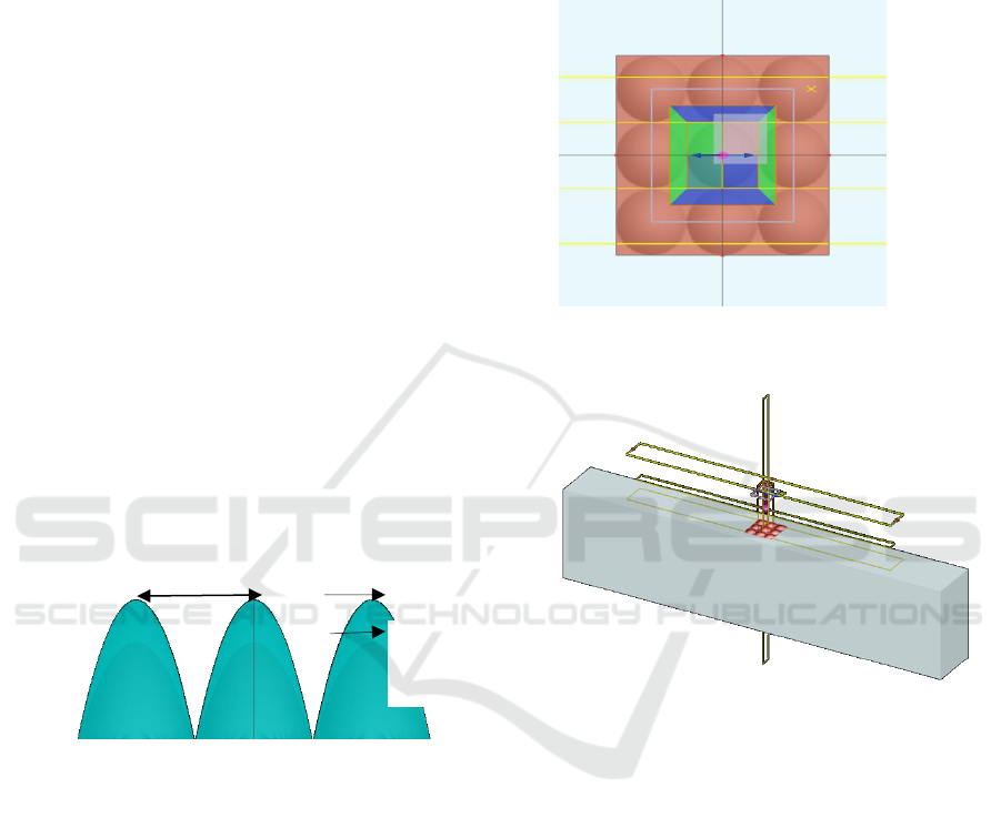
Figure 1: Parabolic shaped Double layer ARC.
In Figure 1, the parabolic shaped double layer
motheye anti-reflectors are shown. The pitch of both
the layers are carefully tailored in order to reduce the
reflection losses. The dimension of double layer
motheye Antireflective coatings such as thickness,
pitch and height are tailored from the Fresnel’s
reflection theory.
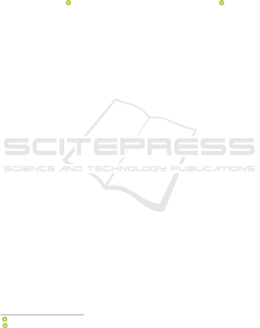
Figure 2 and Figure 3 shows the modelling of Double
layer ARC placed on the glass substrate which is
periodic in nature and are tapered at the sides of the
structure. This simulation is carried out to get the
insight of absorption and transmission in the DLAR.
The following boundary conditions are used to model
the DLAR: x (maximum) = anti symmetric and y
(maximum) = symmetric. Also two monitors are
placed to get the reflection analysis behind the source
and other monitors amount of transmission. The plane
wave is chosen to get the effects of ARCs with
Bloch/periodic wave type. The transmission,
reflection and absorption plots are extracted from the
above simulation set up. The modeling is done using
a commercially available Lumerical FDTD software.
Figure 2: Modelled Double layer Anti-Reflective coatings
(XY view).
Figure 3: Perspective View of DLAR.
In DLAR, two reflectance’s are considered so that
maximum reflection is supressed by undergoing
destructive interferences at two interfaces. One at top
layer and bottom layer ARC interface and another at
bottom layer and glass substrate interface.
Figure 3, shows following layers: Glass substrate,
Bottom layer ARC, Top layer ARC and air medium.
The multilayer stack layers are chosen at different
refractive indices that satisfies following condition.
n
0
< n
top
< n
bottom
< n
substrate
where, n
0
= Refractive index of the air ,
n
top
=
Refractive index of top layer Anti-reflective coating
n
bottom
= Refractive index of Bottom layer Anti-
reflective coating, n
substrate
= Refractive index of the
substrate.
The anti-reflection stack is designed for a particular
wave length of 540nm to emit green fluorescent light.
Top Layer
ARC
Bottom
layer ARC
Pitch
Modeling and Analysis of Double Layer Motheye Anti Reflective Coatings on Organic Light Emitting Diode
191
In this simulation, the reflection and transmission
spectra are obtained. The reflection is almost
supressed compared to SLAR. The DLAR coatings
are also called as V-coatings, since the spectral
patterns are obtained is V-shaped, due to quarter –
quarter coatings or thickness relationship. These V-
shaped coatings are perfectly suitable for the point of
care applications as discussed in (Lee et.al. 2016) and
in OLED based bio sensors as in (Krujatz et.al. 2016).
2.2 Design of DLAR based OLED
This section describes the design and modelling of
Double layer Anti-reflective coating (DLAR) based
OLED.
2.2.1 Design of Fluorescent OLED
The DLAR based Fluorescent OLED shown in the
Figure 4. It contains multi-layer stack with Alq3-Tris
(8-hydroxyquinoline) aluminum as an Organic layer
placed in between anode and cathode. The Alq3 is
chosen in order to emit green light at an operating
wavelength of 540nm. The work function of the
various layers used in the proposed OLED structure
is chosen from (Novotny et al., 2006).
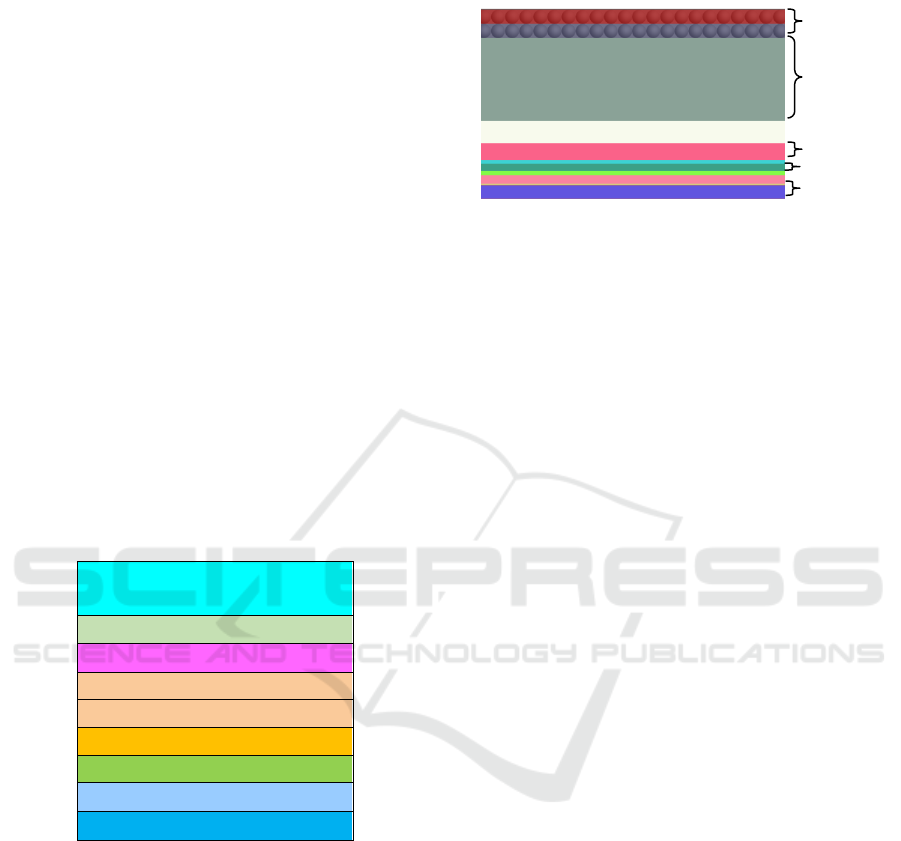
Double layer Anti-
reflective coatings
Glass Substrate
Anode-ITO-120nm
HIL=CuPc=15 to 30nm
HTL=TPD=40nm
NDP=30nm
Alq3=60nm
HBL=BCP=30nm
Cathode=Al=100nm
Figure 4: DLAR based Fluorescent OLED.
The refractive index of the materials and the structure
of the OLED used in the present work is referred from
the literature (Chaya et al., 2018). The DLAR is
placed on the surface of the substrate to avoid the light
trapped inside the layer. The maximum light is
coupled out to supress the losses due to reflections.
The simulation of the DLAR based OLED is carried
out using Lumerical FDTD.
Figure 5, shows the modeled double layer motheye
Anti-reflective coatings based OLED for the structure
shown in Figure 4. To obtain Fluorescent based
OLED device, the Alq3 organic material is used that
operates at 540nm. This layer is placed in emissive
layer.
Figure 5: Modelling of OLED using DLAR (XY View).
The double layer moth-eye Anti-reflective coatings
are made of top layer and bottom layer. The
Magnesium Fluoride and Mesoporous silica are used
as top and bottom layers of DLAR respectively.
These layers are placed on surface of the glass
substrate of the OLED to suppress reflections that
exist on the substrate-air interface. The materials used
in DLAR based OLED device are detailed as follows,
Indium Tin oxide as anode, Aluminum as Cathode,
BCP-(2, 9 Dimethyl-4, 7-diphenyl-1 as Hole
Blocking Layer (HBL), CuPC- (Copper (II)
phthalocyanine) as Hole Injection layer(HIL), (N, N’-
Bis (3-methylphenyl)-N,N’-diphenyl benzidine) as
Hole Transport layer(HTL)-TPD, Tris(8-
hydroxyquinoline) aluminum (Alq3) as emissive
layer, Double layer Motheye Anti-Reflective
Coatings (pitch=300nm, radius=100nm), Glass
Substrate with 1.52 refractive index is chosen in the
present work.
3 METHODOLOGY
The Fresnel’s Reflection theory is used in this work
to model the double layer motheye Anti-reflective
coatings. The reduction in reflectance from the glass-
air interface is achieved by optimising the thickness
of the double layer Anti reflection coatings. By
tailoring the thickness of the Anti-reflective coatings
destructive interferences is achieved to supress
reflection. As discussed in (Lee et.al, 2000), the two
quarter wavelength coatings, the Optimum refractive
index is determined by the equation (1) and (2),
glassairtop
nnn
23
(1)
23
glassairbottom
nnn
(2)
Where, n
top
= Refractive index of top layer Anti-
reflective coating, n
bottom
= Refractive index of bottom
Glass
Substrate
Anode
Organic Layer
Cathode
DLAR
coatings
PHOTOPTICS 2019 - 7th International Conference on Photonics, Optics and Laser Technology
192
layer ARC, n
air
=Refractive index of air, n
glass
=
Refractive index of glass substrate.
Where, n
top
= Refractive index of top layer Anti-
reflective coating, n
bottom
= Refractive index of bottom
layer ARC, n
air
=Refractive index of air, n
glass
=
Refractive index of glass substrate.
4 RESULTS AND DISCUSSION
4.1 Transmission and Reflectance
Patterns of DLAR
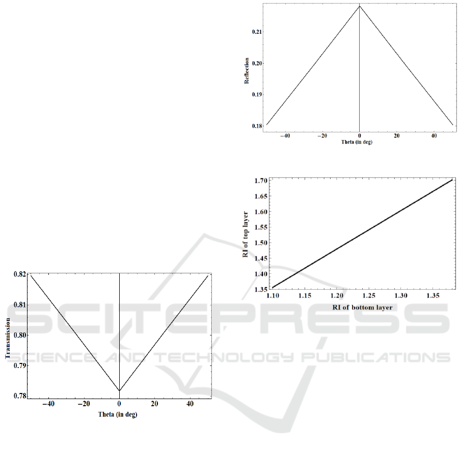
Figure 6 and 7, shows the transmission and
reflectance patterns of the double layer Anti-
reflective coatings with respect to viewing angle. The
transmission and reflectance patterns are obtained at
an operating wavelength of 540nm. Theta in the
graphs represent the angle at which the light transmits
and reflects normal to the surface.
It is observed from the Figure 6, that the transmission
of DLAR is greatly enhanced.
Figure 6: Transmission Spectra of DLAR.
Also in Figure 7, the reflection is almost suppressed
to zero, helps to reduce the glass substrate-air
interface losses, when this DLAR is placed on OLED.
4.2 Refractive Indices of Top and
Bottom Layer ARC
Figure 8, shows the Refractive index (RI) of Top
layer versus RI of bottom layer of ARC curve. For
different top layer RI values the RI of the bottom layer
ARC varies. Based on this analysis the coating
materials are chosen which is to be placed on the
OLED glass substrate.
Figure 7: Reflection Spectra of DLAR.
Figure 8: RI of Top and bottom coating layers.
4.3 Thickness of Top and Bottom
Layer ARC
Figure 9 shows the thickness of the top layer ARC
calculated for coating materials of different RI of Top
ARC layer.
The curve shows that the thickness varies from 95 to
125 nm for coating materials of RI values ranging
from 1.10 to 1.42. Therefore, this curve ensures that
the ARC thickness is chosen appropriately for a
particular coating material.
Figure 10 shows the thickness of the bottom layer
ARC calculated for coating material for different
bottom layer ARC. The curve shows that the
thickness varies from 80nm to 100 nm for coating
materials of RI values ranging from 1.35 to 1.70.
Modeling and Analysis of Double Layer Motheye Anti Reflective Coatings on Organic Light Emitting Diode
193
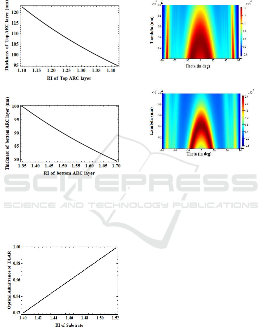
Figure 9: Thickness of Top ARC layer.
Figure 10: Thickness of Bottom ARC layer.
4.4 Optical Admittance and Far Field
Profile of OLED
Figure 11 shows the optical admittance of the double
layer motheye anti-reflective coatings. The curve
shows the optical admittance of the substrate coated
with a quarter wave optical thickness of the DLAR.
Figure 11: Optical Admittance of DLAR.
Figure 12 (a): Far field intensity of Single layer ARC.
Figure 12 (b): Far field intensity of Double layer ARC.
The Far field intensity of the Single layer Anti-
Reflective coating on the surface of the substrate of
the OLED is shown. The materials chosen for the
coatings is Mesoporous silica with refractive index of
1.1.
The far field intensity achieved is about 1.7x10
-5
V/m
as shown in Figure 12 (a). When double layer
coatings of Magnesium Fluoride (MgF
2
) (top layer
ARC)
/ Mesoporous silica (bottom layer ARC) is
coated on the surface of the glass substrate of the
OLED.
The maximum reflection is supressed and far field
electric intensity is achieved of about 2.4 x 10
-5
V/m
compared to single layer ARC placed on OLED as
shown in Figure 12(b). It is observed that, the DLAR
based OLED performance enhances the far field
electric intensity compared to conventional OLED
devices.
5 CONCLUSIONS
In this work, the effects of reflectance and
transmittance of double layer motheye Anti-reflective
coatings are investigated. The thickness of the two
layer ARC are modelled using Fresnel’s theory. This
is done to reduce maximum reflections that imposes
losses on the substrate-air interface. Comparative
PHOTOPTICS 2019 - 7th International Conference on Photonics, Optics and Laser Technology
194

study is carried out for both DLAR and SLAR placed
on OLED. The enhancement in the far field intensity
is achieved with DLAR based OLED is 2.4 x 10
-5
V/m
in greater in comparison with single layer ARC
placed on OLED of about 1.7x10
-5
V/m. Based on
these simulations the reflection losses are reduced at
the glass-air interface of an OLED. Such DLAR
based OLED can be prepared to effectively use in
display and lab-on a chip applications.
ACKNOWLEDGEMENTS
The authors would like to thank Science and
Engineering Research Board, Department of Science
and Technology (DST-SERB) Government of India
for funding this research work.
File No. YSS/2015/000382
REFERENCES
Tang,C.W. and VanSlyke, S.A., 1987. Organic
electroluminescent diodes. Applied physics letters,
51(12), pp.913-915.
Tang, C.W., VanSlyke, S.A. and Chen, C.H., 1989.
Electroluminescence of doped organic thin films.
Journal of Applied Physics, 65(9), pp.3610-3616.
Shockley, W. and Read Jr, W.T., 1952. Statistics of the
recombinations of holes and electrons. Physical review,
87(5), p.835.
Macleod, H.A. and Macleod, H.A., 2010. Thin-film optical
filters. CRC press.
Lee, Y.J., Kim, S.H., Huh, J., Kim, G.H., Lee, Y.H., Cho,
S.H., Kim, Y.C. and Do, Y.R., 2003. A high-extraction-
efficiency nanopatterned organic light-emitting diode.
Applied Physics Letters, 82(21), pp.3779-3781.
Wasey, J.A.E. and Barnes, W.L., 2000. Efficiency of
spontaneous emission from planar microcavities.
Journal of Modern Optics, 47(4), pp.725-741.
Kim, K.H. and Park, S.Y., 2016. Enhancing light-extraction
efficiency of OLEDs with high-and low-refractive-
index organic–inorganic hybrid materials. Organic
Electronics, 36, pp.103-112.
Sharma, R., Amit, G. and Ajit, V., 2017. Effect of single
and double layer antireflection coating to enhance
photovoltaic efficiency of silicon solar.
Dhungel, S.K., Yoo, J., Kim, K., Jung, S., Ghosh, S. and Yi,
J., 2006. Double-layer antireflection coating of
MgF2/SiN x for crystalline silicon solar cells. Journal
of the Korean Physical Society, 49(3), pp.885-889.
Tan, G., Lee, J.H., Lan, Y.H., Wei, M.K., Peng, L.H.,
Cheng, I.C. and Wu, S.T., 2017. Broadband
antireflection film with moth-eye-like structure for
flexible display applications. Optica, 4(7), pp.678-683.
Keshavarz Hedayati, M. and Elbahri, M., 2016.
Antireflective coatings: Conventional stacking layers
and ultrathin plasmonic metasurfaces, a mini-review.
Materials, 9(6), p.497.
Katchman, B.A., Smith, J.T., Obahiagbon, U., Kesiraju, S.,
Lee, S.E., Choi, S.W. and Yi, J., 2000. Double-layer
anti-reflection coating using MgF2 and CeO2 films on
a crystalline silicon substrate. Thin Solid Films, 376(1-
2), pp.208-213.
Lee, Y.K., O’Brien, B., Kaftanoglu, K., Christen, J.B. and
Anderson, K.S., 2016. Application of flat panel OLED
display technology for the point-of-care detection of
circulating cancer biomarkers. Scientific reports, 6,
p.29057.
Krujatz, F., Hild, O., Fehse, K., Jahnel, M. and Werner, A.,
2016. Exploiting the potential of OLED-based photo-
organic sensors for biotechnological applications.
Chem Sci J, 7, p.134.
Chaya B M, et al. FDTD Modeling and Simulation of
Organic Light Emitting Diode with Improved
Extraction Efficiency using Moth-eye Anti-Reflective
Coatings, Proceedings of the 6th International
Conference on Photonics, Optics and Laser Technology
(PHOTOPTICS 2018), pages 266-272.
Novotny, L. and Hecht, B.2006. Principles of Nano-
Optics, Cambridge, Cambridge University Press
Modeling and Analysis of Double Layer Motheye Anti Reflective Coatings on Organic Light Emitting Diode
195
