
A Coincidence Counting System for Twelve-photon Entanglement
Experiment
Yi Hu
1,2
, Wei Li
1,2
, Yue-fei Wang
1,2
, Ge Jin
1
and Xiao Jiang
1,2
1
Hefei National Laboratory for Physical Sciences at Microscale and Department of Modern Physics,
University of Science and Technology of China, Hefei 230026, China
2
CAS Center for Excellence and Synergetic Innovation Center in Quantum Information and Quantum Physics,
University of Science and Technology of China, Hefei 230026, China
Keywords:
Multi-photon, Coincidence Counting, Scalability.
Abstract:
Multi-photon entanglement is an important resource for photonic quantum information, and its scale has
reached 6 photons with 18 qubits or 10 photons with 10 qubits. The upcoming challenge will be 12 pho-
tons with 12 qubits. In the entanglement experiments of such a plurality of photons, the coincidence counter
has always been an important tool, and the experiment of 12 photons poses new requirements. Here we report
the upgrading of a coincident counting system that worked well in 6-photon and 10-photon experiments to the
coming 12-photon one. The scalability of the coincident counting system has been shown. By optimizing the
logic in the Field Programmable Gate Array(FPGA) and the LabVIEW program, not only the number of input
channels has been increased for 12 photons, but also the functions of signal alignment and status monitoring
have been improved. The coincidence result can be analysed both in real-time and off-line. The system is
capable to extend to 104 channels at most for channel consuming application.
1 INTRODUCTION
Quantum information science makes great progress
in recent decades, where quantum entangle-
ment(Einstein et al., 1935; Schr
¨
odinger, 1935)
always lies at the heart. At the most fundamental
level, quantum entanglement represents the intrinsic
non-locality(Brunner et al., 2014) and thus serves
to clarifying essential understandings of quantum
physics. On the other hand, quantum entanglement
is the resource of quantum computation(Knill et al.,
2001; Kok et al., 2007). For these reasons, generating
and testing the quantum entanglement of a large
quantity of qubits in experiments becomes one of the
main target of the quantum information science.
To study the quantum entanglement, the system
of linear optics constitutes one nice platform due
to the well-developed techniques to control photonic
qubits. However, the non-deterministic generation
of entangled photon pairs prevents the scaling-up of
the system. In order to overcome this bottleneck, ef-
forts are made to improve the entangled photon pair
source, which is normally from an ultrafast pulsed
laser pumped spontaneous parametric downconver-
sion (SPDC)(Pan et al., 2012; Kwon et al., 2008; Kim,
2003). Recently, with the progresses of the SPDC,
the entanglement of 10 qubits with 10 photons(Wang
et al., 2016; Chen et al., 2017) and 18 qubits with 6
photons (Wang et al., 2018; Wang et al., 2015) are
realized. What’s more, as an optimal SPDC photon
source of 97% heralding efficiency and 96% inde-
pendent single photons’ indistinguishability has been
achieved(Zhong et al., 2018), it is hopeful to increase
the number of entangled photons continuously. Now
the next landmark is the 12-photon entangled state. In
this context, for the detection of entanglement of more
photons, the correlated measurement brings new chal-
lenges for the coincidence counting system.
The coincidence counting system usually cor-
responds to a type of instrument that records
the time correlation between single-photon de-
tectors(SPDs)(Hadfield, 2009; Farr, 2012) within
a small time window. Historically, an general
method of coincidence counting called time-to-
amplitude(TAC)(Crotti et al., 2012; Simms, 1961) is
proposed and implemented, in which the arrival times
of different photons are converted to the pulse ampli-
tudes. Though having a high time resolution on the
order of picoseconds, this method consumes a large
amount of resource. An alternative way is to initi-
ate the pattern sampling(Gaertner et al., 2005) into
a latch with trigger signals generated by a electronic
Hu, Y., Li, W., Wang, Y., Jin, G. and Jiang, X.
A Coincidence Counting System for Twelve-photon Entanglement Experiment.
DOI: 10.5220/0007371300390045
In Proceedings of the 7th International Conference on Photonics, Optics and Laser Technology (PHOTOPTICS 2019), pages 39-45
ISBN: 978-989-758-364-3
Copyright
c
2019 by SCITEPRESS – Science and Technology Publications, Lda. All rights reserved
39
(a)
Optical Part SPD Part Coincidence counting Part
le
Pulsed Laser
optics
for
the
entangle-
ment
Fiber
Detector Pre-amplify
I/O boards
pulse
discriminator
Backplane signal transmission
Main board
coincidence
counting
Data processing
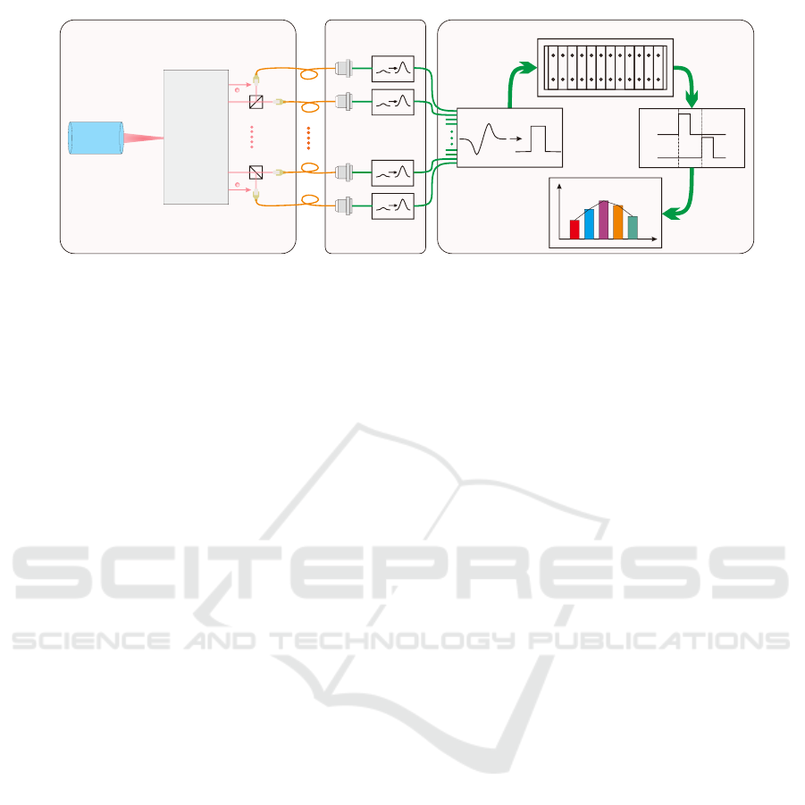
Figure 1: Experimental setup. The pulsed laser generates at most 12 entangled photons. The two states of each photon
could be distingushed with two SPDs. The I/O boards collect and discriminate the input signals. I/O boards are inserted in
Backplane to transfer signals to the Main board. The Main board implement coincidence logic and complete statistic analysis
on personal computer.
logic OR gate. This method suffers from an low event
rate of 0.8MHz. Now there are also some commercial
solutions for Time-Corrected Single Photon Counting
(TCSPC)(Wahl et al., 2013) . Nevertheless, the mea-
surement range is restricted in 5ns and can only be
used with double channels. Therefore a home-made
coincidence counting system should be designed for
multi-photon entanglement experiments.
Previously, a coincidence counting system with
48-channel input signals(Zhang et al., 2016) is estab-
lished for 6-photon entanglement experiment. The
system utilizes the internal delay line of Field Pro-
grammable Gate Array (FPGA) to align the input sig-
nals and compress the pulses by logic constrains. Af-
ter these pre-processing of input signals, the clock
phase is shifted to sample signals and the results are
stored in the external random access memory. The
system following the same structure shows the fine
scalability and reconfigurability, which supports 104
channels and 1 Gbit data size at most. While in the 12-
photon entanglement experiment, the channel num-
ber and the data volume are both within the maxi-
mal range. So it is practical to upgrade and remodule
the original system to service the new experiment and
meet new requirements.
In this letter, we present a coincidence counting
system with 24 input channels for 12-photon entan-
glement experiment on the basis of the coincidence
counting scheme for 6 photons. This successful up-
grading confirms the fine scalability of the 48-channel
coincidence counting system in the 6-photon entan-
glement experiment.
2 REALIZATION
The holistic structure of the 12-photon entanglement
experiment is shown in Figure 1. The whole ex-
periment can be divided into three parts: the opti-
cal Part, the single photon detector(SPD) part and
the coincidence counting part. In the optical part, a
76MHz laser produces pulses of photons, which go
through the system of linear optics for generating the
12-photon entanglement. Later for each photon its
two states can be distinguished with two SPDs, thus
24 SPDs are needed to record those 16,777,216 (2
24
)
sorts of coincidence events. These detectors sample
the optical pulses and pre-amplify input signals. Fi-
nally the coincidence counting part relies on a suit of
hardware which consisted of six I/O boards, one Main
board and one Backplane, shown in Figure 2.
2.1 The Hardware Platform
The I/O board is used to capture and transfer the
input signals from detectors. One I/O board has 8
identical channels composed of an I/O port, an am-
plitude, a comparator and a digital potentiometer.
They work together as an flexibly adjustable thresh-
old discriminator uniting the configurable FPGA(
EP4CE6E22CSN) for adapting the amplitudes of in-
put signals. To reduce crosstalk between channels, the
input and output channels in I/O boards are arranged
in a staggered configuration: the adjacent channels of
the inputs are configured as output GNDs. So each
I/O board supports 4 channels of input signals and 6
pieces of I/O board are required for the 24 channels
of the 12-photon entanglement.
In the system, the Main board plays a central
role of performing coincidence logical operations,
PHOTOPTICS 2019 - 7th International Conference on Photonics, Optics and Laser Technology
40
Peripherals
1Gbit
DDR
128
Mbit
Flash
16Mbit
SPI
Flash
Power
User
LED
JTAG
Xilinx FPGA
Spartan 6
XC6SLX16CSG324-2
USB 2. 0
CYPR ESS FX2
64 kb
I2C
EEPROM
USB
Connec to r
24M
Oscill at or
48M
Oscill at or
160 pin
signal
female
connector
Peripherals
USER
LEDs
USB
2.0
Toggle
Switch
8 channe ls
Altera FPGA
EP4CE6E22C8N
JTAG
100M
Oscill at or
Power
Clock si gn al
100 MHz
96 pin
signal
female
connector
Lemo
connec to r
Amplifi er
compar at or
potent io -
meter
(a) I/O board
(b) Main board
(c) Backplane
8 channe ls
8 channe ls
24 chann el s
Clock si gn al
76 MHz
Powe r
x8
x8
x8
x8
x8
x8
x8
x8
x8
x8
x8
x8
Main
I/O
I/O I /O
I/O I /O
I/O
I/O I /O
I/OI/OI/O
I/O
Slot0 Slot1 Slot2 Slo t3 S lo t4 Slot5 Slot6 S lo t7 S lo t8Slot13Slot12Slo t11S lo t1 0
x8
I/O
Slot9
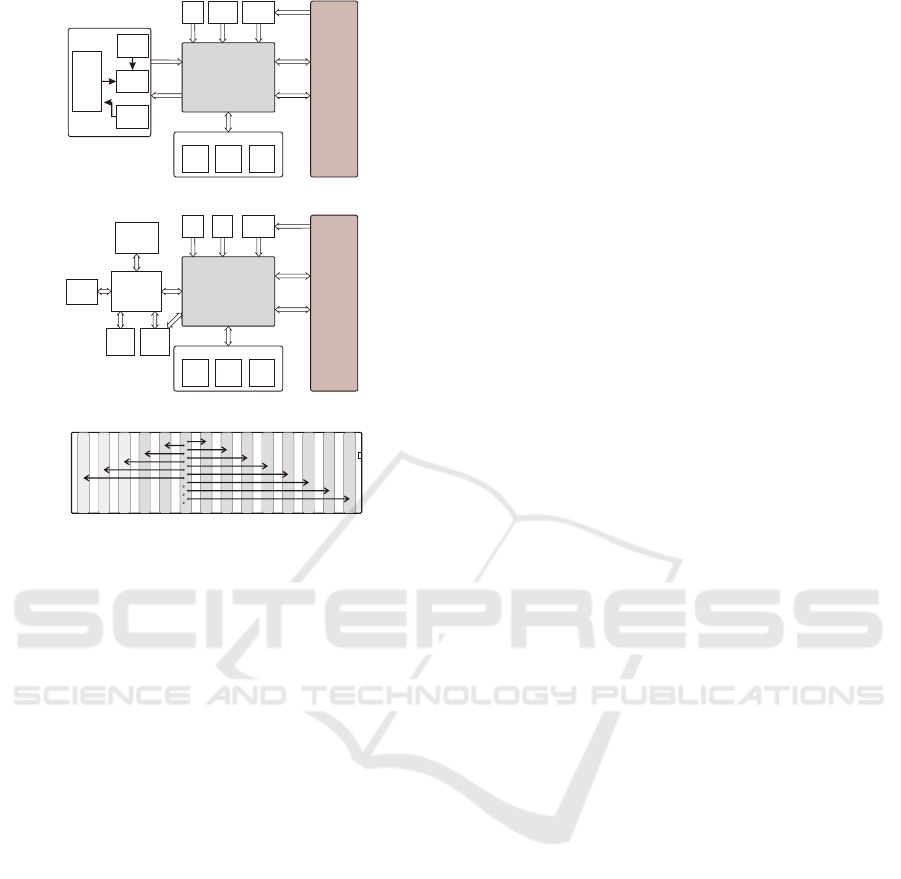
Figure 2: (a) The framework of I/O board. (b) The frame-
work of Main board. (c) The framework of Backplane.
system control and data processing. It contains a
low-end spartan6 (XC6SLX16CSG324C) FPGA, a
USB2.0 (CY7C68013A) and a 1 Gbit low-power
DDR (MT46h64M16LFCK). The FPGA realizes the
architecture of a WISHBONE bus. The DDR is put
into use to store the excess data when the data size ex-
ceeds the volume of on-chip memories. And the read-
ing and writing of the DDR by FPGA is completed
by the MCB(Memory Control Block). The address
space of the WISHBONE bus is divided into sev-
eral blocks for DDR, Block RAM on-chip and Regis-
ter groups. Accessing these different addresses leads
to the operations for corresponding memory devices.
Here all the devices communicate with the personal
computer(PC) via the USB.
The I/O and Main boards are all plugged into the
Backplane and then integrated in 3U chassis. The
Backplane has 14 slots in total: the slot0 is for the
Main board and the other 13 slots are for the I/O
boards. The slot1 to slot13 each has 8 data wires con-
necting with the slot0 individually. The output signals
from I/O boards are collected at the Main board by the
backplane data buses.
2.2 The New Challenges
In the coincidence counting system for the photon en-
tanglement, there are 4 key elements: signal align-
ment, pulse width, signal sampling and data process-
ing. In order to carry out these tasks, a logic architec-
ture is designed in the FPGA of Main board and the
corresponding software is programmed. In the 12-
photon entanglement experiment, we face with sim-
ilar difficulties in general. Besides, new challenges
arise due to the increase of photon number and also
new requirements from users. Firstly, the new sys-
tem is expected to show more sorts of counting re-
sults in real-time and enable the control of the motion
controller(ESP301) to scan the length of optical path
of entangled photons. Furthermore, arbitrary type of
coincidence events needs to be read out while previ-
ously only some specific coincidence events can be
shown. Another tough task is to adopt the different
address definition for different number of photons. In
other words, the modules involving the access to the
addresses of coincidence events all need to be rede-
fined. Here we make partial adjustments to complete
the new architecture depending on the existing one,
which is Shown in Figure 3.
2.2.1 Techniques of Pulse Scan
Signals would have different time delays accumulated
in different optical and electronic paths. In the past,
after comparing these signals with a oscilloscope, the
alignment of signals is performed by changing the
lengths of cables manually, which is repetitive and
onerous work. In the 6-photon entanglement exper-
iment, techniques of pulse scan are adopted to align
the input signals. Shifting the phase of clock step by
step, the relation between the single photon count and
the shifted clock phase is obtained, based on which
the arrival time of signals can be determined. Then all
the other signals would be aligned with the last arriv-
ing one by the internal delay block. Thus, the manual
adjustment of the cables is no longer necessary.
In our new coincidence system, we modify and
improve these pulse scan techniques. First of all, we
scan the single-channel count instead of the single-
photon count. The single channel count includes
not only the single-photon count but also the multi-
photon counts involving this channel together, which
indicates the counting would get started as soon as the
detector has response. The counting result in this way
is more accurate than before since the multi-photon
coincidence events are not missing in the statistics.
This is also better cost-saving during the test because
we can obtain the whole channel scan curves simulta-
neously in a clock period with a signal source. While
A Coincidence Counting System for Twelve-photon Entanglement Experiment
41
CH1
Ch2
CH1
CH2
CH1
CH2
PC
WISHBONE BUS
From synchronous CLK
Signalx24
DCM
Internal
Delay
Pulse
Reshaping
Latch
FIFO
Data
Redistributor
Internal
RAM
External
DDR
Register
Group
FPGA
USB
Scan
and
Align
Acquire
and
Monitor
Scan
and
Trace
Data
Read-Out
Shifted CLK
PC
(a) Logic architecture of Main board
Labview
Stepper Motor
RS232
(b)Software architecture for Main board
Software
CH1
CH2
CH24
CH1
CH2
CH24
CH1
CH2
CH24
CH1
CH2
CH24
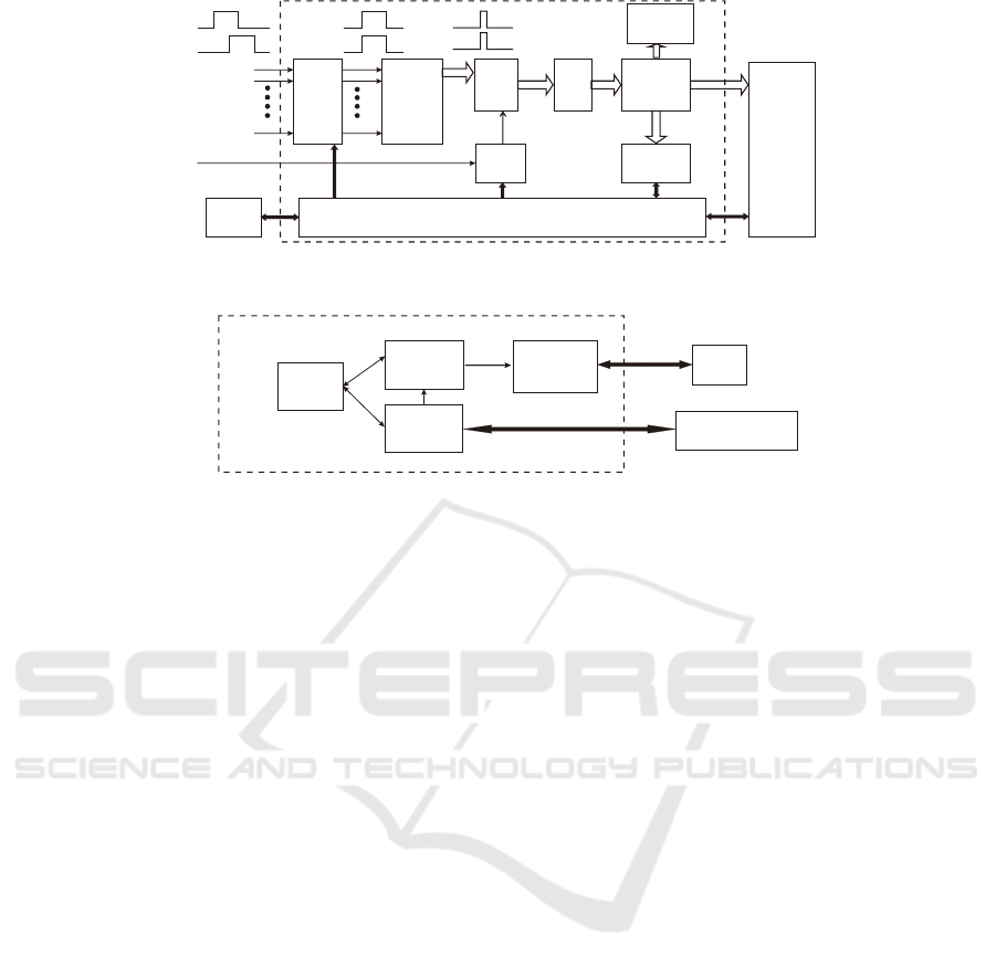
Figure 3: (a)The logic architecture of the Main board. The internal delay block adjust the delay line of FPGA to align the
input pulses. The pulse reshaping block narrow the pulsed width. The clock phase can be shifted by step and the sampled
data is distributed to different memory. (b)The software architecture for Main board. The software access the address of the
memories by WiSHBONE bus and the software are programmed by Labview.
in the past, to produce the single photon event of the
all channels, we have to set up an additional test sys-
tem to send signals in sequence every other cycle.
2.2.2 The Scheme of Data Storing
After the alignment of signals, the pulse reshaping
block is then used to compress the pulse width and
as a result the effects of inter-symbol interference and
dark count are eliminated. This block is kept un-
changed compared to the preceding coincidence sys-
tem. The narrowed pulses will be registered into
FIFO(First in, First out) at the rising edge of syn-
chronous clock which shifts the phase to the center
of the pulses. These data in the FIFO are then writ-
ten into different memory locations according to their
coincidence types. Thus, the scheme of address cod-
ing is determined by the number of entangled photons
and the size of data in the experiment.
In the 12-photon experiment, only a single degree
of freedom, ie. the polarization, of each photon is
taken into account, so two detectors would respond to
the state of one photon. For this reason, we can use 2
bits to describe completely the photon state. Totally,
24 bits are needed to record all sorts of 12-photon co-
incidence event, so each bit array can just take the
place of the memory address to store the correspond-
ing coincidence counting. Moreover, since the experi-
ment of multi-photon entanglement normally lasts for
several days and leads to a huge amount of data, a 64-
bit counter is defined which ensures enough space for
all counting results and any overflow can be avoided.
The total storage space in need is 1 Gbits(2
24
*64 =
2
30
= 1 G) which exceeds the volume of the internal
block RAMs, so the excess data should be distributed
to the external DDR. In the experiment, the appear-
ance of photons in pulses follows a Poisson distri-
bution. The single photon and 2-fold events occupy
the primary body, which respectively take 24 and 528
sorts of coincidence. Though the multi-fold (more
than 2-fold) events is rare, their types of coincidence
increase exponentially. So we put multi-fold events
in DDR while single photon and 2-fold coincidence
events are stored in the block RAMs with 10 bits of
address.
In addition, register groups distinguished as the
register-in group and the register-out group are added
to the system. The register-in group collects read-out
information from FPGA to PC like the status indicator
and the single-channel coincidence counting results,
while the register-out group carries the write-in mes-
sages from PC to FPGA including the control com-
mands. The register groups can offer favourable com-
munication medium for PC and the counting system.
PHOTOPTICS 2019 - 7th International Conference on Photonics, Optics and Laser Technology
42
(a)
(b)
0 2 4 6 8 10
Clock Shifting (ns)
0
2x10
4
4x10
4
Count
0
2x10
4
4x10
4
Count
Before Alignment
After Alignment
0 2 4 6 8 10
Clock Shifting (ns)
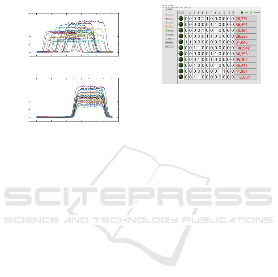
Figure 4: Pulse scan of 24 channels before and after align-
ment.(a)Before the delay adjusting, the arrival time of dif-
ferent channels differ greatly. (b)After the delay adjusting,
the arrival time of different channels are almost uniform.
2.2.3 The Relative Software
All the programs controlling our coincidence count-
ing are coded with Labview. One program named
“Scan and Align” helps the users to set parameters
concerning the alignment of the signals such as delay
value and clock phase shifting. It can access the reg-
ister groups and scan the single channel coincidence
counting.
After the alignment, another program named “Ac-
quire and Monitor” is used to configure the process to
acquire and monitor the coincidence results. Particu-
larly, with this program the measurement can be dis-
played in real-time, which makes it easier to take con-
trol over the experiment. To realize this function, we
select the wanted type of coincidence events and read
out the counting results from the memories. How-
ever, the exponential increase in the time cost to tra-
verse all sorts of coincidence would retard the refresh-
ing of the program. So in order to retain the refresh
rate high than 1s
−1
, we calculate the approximate re-
sult for only including the appointed N-fold and the
next (N+1)-fold coincidence counting and neglecting
all the others.
Finally, the program named “Scan and Trace”
serves to control the motion controller used for the
optimization of the photon coherence. The controller
moves step by step to obtain a curve of the count rate
which helps to adjust the optical path to the best state.
The last program named “Data Read-Out” can read
out the data of arbitrary appointed coincidence events.
Figure 5: The working interface of the Labview-based con-
trolling program. The test results are displayed on the inter-
face and agree with the estimate from the Possion equation,
demonstrating the right working status of the system.
3 TEST AND RESULT
To test the alignment of output signals in the experi-
ment, we send simulating signals to all the 24 SPDs
and then compare waveforms of the output signals be-
fore and after alignment, as shown in Figure 4. It can
be seen that the maximum time difference before the
delay alignment is about 3ns, but after adjusting the
delay line, the time difference is around 0.4ns. The
alignment operation provides a narrow time coinci-
dence window and a wide steady sampling window.
What is more, the pulse width can be deduced from
the test. When the count is stable, the width of the flat
top can be considered as the signal pulse width. In the
experiment, the pulse width is about 3ns.
One of the user interface about displaying in real
time during experiment is shown in Figure 5. In the
figure, each row represents a sort of coincidence event
( “1”,“2” represent the detector response, “0” repre-
sent opposite.). We choose to display coincidence
of photon pairs from either the same entanglement
source or different source. The users first count the
every pair source event and then estimate the coinci-
dence count by the Possion equation. When the result
of computation agrees with that displayed in real time,
the counting system is demonstrated to work reliably.
With our coincidence counting system, we are
able to optimize the photon coherence at the detectors
on the basis of a Hong-Ou-Mandel(HOM)-type inter-
ference test. The coincidence counting rates of four
photon detectors recording the four output channels
of the HOM experiment are measured, as the length
of one interfering path is scanned via a mirror tunable
with a motion controller. The optimal position of the
mirror is approached when the detectors the coinci-
dence of two transmitting photons and two reflecting
photons reach its maximal value and at the same time
the coincidence of one transmitting photon and one
A Coincidence Counting System for Twelve-photon Entanglement Experiment
43
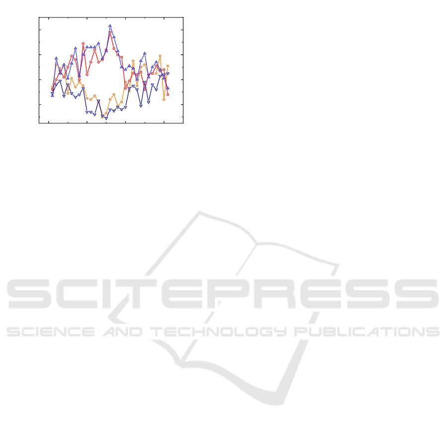
reflecting photon is the minimal, as shown in Figure
6.
0 1 0 0 2 0 0 3 0 0
4 0
6 0
8 0
1 0 0
C o u n t / s e c
P o s i t i o n ( µm )
Figure 6: The coincidence counting rates of four photon
detectors recording the four output channels of the HOM
experiment.
4 CONCLUSIONS
Based on the original system applied in 6-photons 18-
qubit experiment, we develop a reconfigurable coinci-
dence counting system with 24 input channels for 12-
photon entanglement experiment. Compared to the
previous scheme, we apply the former architecture
and perform a plenty of improvements. We adjust the
delay to align the input pulses and after alignment, the
maximum time deviations between output signals is
no more than 0.4ns. We place pulse reshaping blocks
to compress the input signals and achieve a average
pulse width of 3ns. Furthermore, we adopt the differ-
ent address coding method to count and distribute the
data to different memories. The maximum bandwidth
supports 90Mhz and the maximum data size supports
over 1Gbit. Finally, this coincidence counting system
is demonstrated to be feasible in the experiment of
12-photon entanglement.
In the future, some issues are still requires further
optimization. With the quantity of channels increas-
ing, the crosstalk between channels will get worse.
Next we would take more attempts to improve sig-
nal integrity. Besides, since the backplane bandwidth
is not high enough, the single-terminal routing can
be changed to the differential routing to increase the
bandwidth to GHz.
ACKNOWLEDGEMENTS
This work has been financially supported by the Na-
tional Natural Science Foundation of China (Grant
Nos.61575185 and 61308014), and the CAS Key
Technology Talent Program. The author would like
to thank Zheng-da Li and Rui Zhang for his feedbacks
and discussions. We especially thank Prof. Jian-Wei
Pan for his guidance and support.
REFERENCES
Brunner, N., Cavalcanti, D., Pironio, S., Scarani, V., and
Wehner, S. (2014). Bell nonlocality. Rev. Mod. Phys.,
86:419–478.
Chen, L.-K., Li, Z.-D., Yao, X.-C., Huang, M., Li, W., Lu,
H., Yuan, X., Zhang, Y.-B., Jiang, X., Peng, C.-Z., Li,
L., Liu, N.-L., Ma, X., Lu, C.-Y., Chen, Y.-A., and
Pan, J.-W. (2017). Observation of ten-photon entan-
glement using thin bib3o6 crystals. Optica, 4(1):77–
83.
Crotti, M., Rech, I., and Ghioni, M. (2012). Four channel,
40 ps resolution, fully integrated time-to-amplitude
converter for time-resolved photon counting. IEEE
Journal of Solid-State Circuits, 47(3):699–708.
Einstein, A., Podolsky, B., and Rosen, N. (1935). Can
quantum-mechanical description of physical reality be
considered complete? Phys. Rev., 47:777–780.
Farr, W. H. (2012). Overview of single photon detection
technologies. In IEEE Photonics Conference 2012,
pages 20–21.
Gaertner, S., Weinfurter, H., and Kurtsiefer, C. (2005). Fast
and compact multichannel photon coincidence unit for
quantum information processing. Review of Scientific
Instruments, 76(12):123108.
Hadfield, R. H. (2009). Single-photon detectors for optical
quantum information applications. Nature Photonics,
3:696.
Kim, Y.-H. (2003). Quantum interference with beam-
like type-ii spontaneous parametric down-conversion.
Phys. Rev. A, 68:013804.
Knill, E., Laflamme, R., and Milburn, G. J. (2001). A
scheme for efficient quantum computation with linear
optics. Nature, 409:46.
Kok, P., Munro, W. J., Nemoto, K., Ralph, T. C., Dowling,
J. P., and Milburn, G. J. (2007). Linear optical quan-
tum computing with photonic qubits. Rev. Mod. Phys.,
79:135–174.
Kwon, O., Cho, Y.-W., and Kim, Y.-H. (2008). Single-mode
coupling efficiencies of type-ii spontaneous paramet-
ric down-conversion: Collinear, noncollinear, and
beamlike phase matching. Phys. Rev. A, 78:053825.
Pan, J.-W., Chen, Z.-B., Lu, C.-Y., Weinfurter, H.,
Zeilinger, A., and
˙
Zukowski, M. (2012). Multipho-
ton entanglement and interferometry. Rev. Mod. Phys.,
84:777–838.
Schr
¨
odinger, E. (1935). Die gegenw
¨
artige situation in der
quantenmechanik. Naturwissenschaften, 23(48):807–
812.
Simms, P. C. (1961). Fast coincidence system based on a
transistorized time-to-amplitude converter. Review of
Scientific Instruments, 32(8):894–898.
Wahl, M., R
¨
ohlicke, T., Rahn, H.-J., Erdmann, R., Kell,
G., Ahlrichs, A., Kernbach, M., Schell, A. W., and
PHOTOPTICS 2019 - 7th International Conference on Photonics, Optics and Laser Technology
44

Benson, O. (2013). Integrated multichannel pho-
ton timing instrument with very short dead time and
high throughput. Review of Scientific Instruments,
84(4):043102.
Wang, X.-L., Cai, X.-D., Su, Z.-E., Chen, M.-C., Wu, D.,
Li, L., Liu, N.-L., Lu, C.-Y., and Pan, J.-W. (2015).
Quantum teleportation of multiple degrees of freedom
of a single photon. Nature, 518:516.
Wang, X.-L., Chen, L.-K., Li, W., Huang, H.-L., Liu, C.,
Chen, C., Luo, Y.-H., Su, Z.-E., Wu, D., Li, Z.-D., Lu,
H., Hu, Y., Jiang, X., Peng, C.-Z., Li, L., Liu, N.-L.,
Chen, Y.-A., Lu, C.-Y., and Pan, J.-W. (2016). Ex-
perimental ten-photon entanglement. Phys. Rev. Lett.,
117:210502.
Wang, X.-L., Luo, Y.-H., Huang, H.-L., Chen, M.-C., Su,
Z.-E., Liu, C., Chen, C., Li, W., Fang, Y.-Q., Jiang, X.,
Zhang, J., Li, L., Liu, N.-L., Lu, C.-Y., and Pan, J.-W.
(2018). 18-qubit entanglement with six photons’ three
degrees of freedom. Phys. Rev. Lett., 120:260502.
Zhang, C., Li, W., Hu, Y., Yang, T., Jin, G., and Jiang, X.
(2016). 48-channel coincidence counting system for
multiphoton experiment. Review of Scientific Instru-
ments, 87(11):113107.
Zhong, H.-S., Li, Y., Li, W., Peng, L.-C., Su, Z.-E., Hu,
Y., He, Y.-M., Ding, X., Zhang, W.-J., Li, H., Zhang,
L., Wang, Z., You, L.-X., Wang, X.-L., Jiang, X.,
Li, L., Chen, Y.-A., Liu, N.-L., Lu, C.-Y., and Pan,
J.-W. (2018). 12-photon entanglement and scalable
scattershot boson sampling with optimal entangled-
photon pairs from parametric down-conversion. ArXiv
e-prints.
A Coincidence Counting System for Twelve-photon Entanglement Experiment
45
