
Acousto-optic Time-Domain Optical Demultiplexer
S. N. Mantsevich and V. I. Balakshy
M. V. Lomonosov Moscow State University, 119991, Lininskiye gory 1, Moscow, Russia
Keywords: Acousto-optic Interaction, Collinear Acousto-optic Filtration, Frequency Locking, Optical Demultiplexer.
Abstract: The design of acousto-optic (AO) time-domain demultiplexer is proposed. The characteristics of such AO
device are examined experimentally. This demultiplexer combines the collinear AO tunable filter used for
the optical spectrum components selection with the optoelectronic feedback circuit and self-oscillations
frequency locking effect. The presented demultiplexer obtain the following characteristics: wavelength
spacing between channels may be less than 1 nm, the channel passband width is 0.4 nm, the crosstalk
attenuation between adjacent channels exceeds 42dB, the insertion loss is less than 2 dB.
1 INTRODUCTION
Optical demultiplexers are important devices in the
fiber-optic communication lines. Many variants of
optical demultiplexers have been proposed using
various physical effects. Among the variety of such
devices were those that applied acousto-optic (AO)
effect. In this case, the options for using both surface
(Sobrinho, 2004, Ghannam, 2005) and bulk acoustic
waves (Kinoshita 1986) were considered. In the case
of bulk acoustic waves an AO deflector was used as
an element performing spectral selection, either as
the main element, or together with the diffraction
grating. In this paper, it is proposed for the first time
to use a collinear AO filter to create the
demultiplexer.
We examine an optoelectronic system that
belongs to the class of acousto-optical (AO) devices
with feedback (Chrostowski, 1982) in this paper.
The signal in the feedback circuit is formed by using
a part of the optical radiation intensity from the AO
cell optical output that goes to the separate
photodetector. The electric signal from this
photodetector passes through the feedback circuit
connecting its output with the AO cell piezoelectric
transducer (Chrostowski, 1982, Balakshy, 2014). It
is known that the feedback appearance expand
substantially the range of optical information
processing problems that can be solved by AO
methods (Balakshy, 1996, Chatterjee, 2011).
It was shown earlier (Mantsevich, 2018,
Mantsevich, 2018) that several operation modes
exist in the system containing the collinear AO filter
and optoelectronic feedback circuit. The first one is
realized at relatively small values of the feedback
gain and is equivalent to the regeneration mode in
radio electronics devices. The AO system in this
case operates like a tunable AO filter (Harris, 1970,
Balakshy, 2007) with one important difference - it is
possible to control the bandwidth and spectral
contrast by changing the electrical parameters of the
feedback circuit (Mantsevich 2018, Mantsevich,
2016, Mantsevich, 2017, ).
The second operation mode is the generation
mode. It takes place at high feedback gain values
(Mantsevich 2018, Balakshy 2004). The
amplification factor is so high in this case that it
becomes possible to maintain the self-oscillations in
the system, so an external RF generator is no longer
needed for its operation. The frequency of RF
oscillations is being determined by the spectrum of
the optical radiation entering the AO filter input and
the AO interaction efficiency is controlled by the
feedback gain. It was shown earlier (Mantsevich,
2018) that in the generation mode, when connecting
the external RF generator, it is possible to observe
the AO system self-oscillations frequency locking
effect. The locking band width will be determined
by feedback gain value and the amplitude of the
external RF signal.
In this paper, we examine the possibilities of
optical radiation spectral composition controlling
that arise when using the frequency locking effect in
the examined AO system. The presented
investigation shows that this system may be used as
Mantsevich, S. and Balakshy, V.
Acousto-optic Time-Domain Optical Demultiplexer.
DOI: 10.5220/0007357800290035
In Proceedings of the 7th International Conference on Photonics, Optics and Laser Technology (PHOTOPTICS 2019), pages 29-35
ISBN: 978-989-758-364-3
Copyright
c
2019 by SCITEPRESS – Science and Technology Publications, Lda. All rights reserved
29
a time-domain demultiplexer in the optic
communication systems.
2 SYSTEM DESCRIPTION
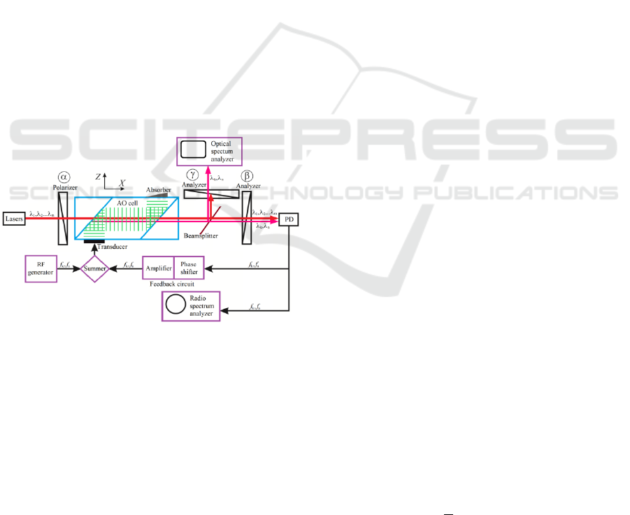
The principal scheme of the examined AO system is
shown in Fig. 1. The basic element of the setup is
the AO filter with the collinear geometry of acousto-
optic diffraction (Harris, 1970). In this geometry, the
wave vectors of the incident and diffracted light
beams, as well as the wave vector of the acoustic
wave excited in the AO cell are collinear.
An optical beam from a light source passes
through the polarizer and enters the collinear AO
cell. The shear acoustic wave propagating along X
crystallographic axis was excited in the AO cell by a
piezoelectric transducer. The light beam passes
through the cell along the X axis collinear to the
acoustic beam. The cell is placed between a
polarizer and analyzers that specify the polarization
of light at angles α, β and γ with regard to the
crystallographic Y-axis. In our experiments, we have
used the AO cell fabricated from a calcium
molybdate crystal with cm AO interaction
length.
Figure 1: The principal scheme of AO demultiplexer.
A distinctive feature of this AO system from the
previously examined (Mantsevich 2017, Balakshy
2016, Mantsevich 2018, Mantsevich 2018) is that
the beamsplitter is mounted before of the output
polarizers, and the polarization plane of the input
polarizer is oriented not at 45 degrees to the Y axis,
but is orthogonal to it (α = 90°). Such positioning of
the beamsplitter allows us to divide the light beam
on the AO cell output into two with polarizations
controlled independently. One of the light beams
passes through the analyzer with the polarization
plane orthogonal (γ = 0°) to the input polarizer
polarization plane. This mutual orientation
corresponds to the standard application of collinear
AO cells when they are placed between crossed
polarizers to separate the diffracted light beam from
the incident one (Harris, 1970). This optical beam
will carry useful information, so let's call it signal.
The second beam will pass through the analyzer,
with the polarization plane oriented at an angle β =
45° to the Y axis. Thus, its intensity will be
modulated by amplitude with the ultrasound
frequency, excited in the AO cell (Balakshy 2009,
Balakshy 2012), which makes it possible to use it for
signal generation on the feedback circuit input, so
we will call it the feedback beam.
The feedback beam is registered by the
photodetector connected to the input of the feedback
circuit. The circuit includes phase shifter and
amplifier that allow tuning the feedback circuit gain
κ over a wide range.
The signal from the feedback output feeds the
piezoelectric transducer of the AO cell. Oscilloscope
or RF signal spectrum analyzer may be connected to
the feedback circuit for the visualization and
analysis of the feedback signal characteristics.
The signal beam characteristics were controlled
by optical radiation spectrum analyzer with 0.06nm
spectral resolution.
Figure 1 presents the schematic diagram of the
examined system in the case of its operation in the
frequency locking mode. In this variant an external
RF generator is used to lock one of the self-
oscillation frequencies. The self-oscillation RF
frequencies in the feedback circuit are determined by
the optical radiation spectrum at the input of the AO
cell. If we use the presented system as the
demultiplexer only the spectral component with
wavelength corresponding to the locked RF
frequency will exist in the signal optical beam on the
system output.
3 BASIC RELATIONS
The theoretical approach we apply in this paper is
based on the model presented in (Balakshy 2016,
Mantsevich 2017). First of all it should be
mentioned that the phase matching condition for the
collinear geometry of AO diffraction is (Harris
1970):
(1)
where
and
are the calcium molybdate
refraction indices, V – ultrasound velocity of the
PHOTOPTICS 2019 - 7th International Conference on Photonics, Optics and Laser Technology
30

slow acoustic mode along the X crystallographic
axis that equals 2.91∙10
5
cm/s, λ – optical radiation
wavelength and f
c
is the ultrasound frequency. This
equation establishes the correspondence between the
incident optical radiation wavelength and the
frequency of RF oscillations in the feedback circuit.
For the calcium molybdate AO cell used in our
experiment the f frequency turned out to be 43.6
MHz for the optical wavelength 632.8nm. The
chosen optical wavelength doesn’t correspond to the
telecommunication wavelengths, but all physical
effects that make the examined system operation
possible remain fair for longer optical wavelengths.
It is also possible to change the calcium molybdate
AO cell with lithium niobate cell (Harris 1969) with
even higher spectral resolution to shift the optical
operation range to near 1.5µm.
It was shown in (Balakshy 2009, Balakshy 2012)
that in general case of the polarizers polarization
planes orientation the optical beam intensity on the
optical output of the system may be described by the
following equation:
(2)
here
is the component that is usually used in
collinear AO filters (Harris 1970), it obtains
maximal value when polarizer is oriented along or
orthogonally to the AO crystal optical axis and
analyzer is perpendicular to the polarizer (this is the
case of the signal beam in the examined AO
system);
component has modulation by intensity
with frequency that is equal to the
ultrasound wave frequency aroused in the AO cell
(the feedback beam in the examined system);
is
the component that has the amplitude modulation
with doubled ultrasound frequency. Variable Φ is
the initial acoustic phase at the AO cell input,
and
are the additional phase shifts appearing at
collinear AO interaction. In the Eq. (2) all
component magnitudes are the functions of polarizer
and analyzer polarization planes orientation angles.
It was shown in (Balakshy 2009, Balakshy 2012)
that choosing the polarizer and analyzer orientations
at angles or and or
and or with regard to the Y
crystallographic axis (the second variant was chosen
for the feedback beam) we will obtain 100%
modulation of diffracted light intensity after the
analyzer with ultrasound frequency aroused in the
AO cell. In these cases the light intensity of the
feedback beam
after the analyzer will be
described by the following equation:
(3)
where
,
- is the incident light
intensity, is the beamsplitter ratio (50:50 in our
case),
is the Raman–Nath parameter
(AO coupling coefficient) proportional to the
acoustic wave amplitude aroused in the AO cell,
is the dimensionless AO
phase mismatch, Δn is the maximal change of the
crystal refractive index under the action of the
acoustic wave, - ultrasound frequency,
- AO
phase matching ultrasound frequency defined by the
Eq. (1)
When the AO phase matching condition is
fulfilled and
. The
amplitude
achieves maximal value 0.5∙ at the
point
. Thus, at this point, the output
intensity changes harmonically in time with the
frequency of ultrasound from zero to full intensity
of light
. This is the only case in the acousto-
optics when AO cell produces amplitude modulation
of the optical beam intensity not after the diffraction
on the standing but on the travelling acoustic wave.
At the same time the signal beam intensity will
be described by the following equation:
(4)
The additional phase shift
appearing at
collinear AO interaction is defined by the equation:
(5)
So we need to include the phase shifter in the
feedback circuit to fulfill the phase balance
condition defined by Eq.(5). It is easy to see that if
the phase matching condition is fulfilled and R=0 the
The detector signal that is also the signal on the
feedback circuit input equals
where is the sensitivity of the photodetector
(V/W). We have chosen for the
calculations. After passing the feedback circuit
feeds the AO cell piezoelectric transducer.
Thus the RF signal on the transducer may be
described by the following equation:
Acousto-optic Time-Domain Optical Demultiplexer
31

(6)
here, is the amplifier gain factor, and χ is the phase
shift produced by the phase shifter. The Eq.(6) value
will be maximal if:
(7)
This equation indicates that the phase shifter has
to compensate the AO phase shift
. And then it is
possible to rewrite Eq. (6) as:
(8)
(9)
The Raman–Nath parameter Γ is proportional to
the acoustic wave amplitude and, consequently, to
the electrical voltage amplitude U
0
applied to the
transducer:
(10)
where µ is transformation the coefficient determined
by characteristics of the transducer and the AO cell.
Measuring the characteristics of the collinear AO
filter used in experimental setup we have defined
that .
Finally it is possible to write the relation that
describes the behavior of the examined AO system:
(11)
here
is the generalized feedback
coefficient. Eqs. (5) and (11) form the phase and
magnitude balance conditions for the examined
system.
The examined system operates above the
excitation threshold and it is possible to treat it as
the AO generator (Balakshy 1996, Balakshy
2004).The feedback gain is high enough to maintain
the constant magnitude of the self-oscillations in the
feedback circuit without the signal from RF
generator. Considering the phase and amplitude
balance conditions it is possible to rewrite the Eq.
(11) and Eq. (5) to define the system self excitation
border:
(12)
(13)
The missmatch
in the generation mode.
It is possible to obtain the gain values corresponding
to the system excitation threshold from Eq. (12). We
should consider the missmatch
to define the
excitation threshold. Then threshold feedback
coefficient values will be described by equation:
(14)
Considering Eq.(13) and (14) it s possible to
notice that there is no dependence on optical
radiation wavelength, only intensity is involved. So
if optical radiation on the optical input of the system
contains several spectral components with intensities
higher than those required by Eq. (14), then the
frequencies corresponding to them in accordance
with Eq. (1) will be excited in the feedback circuit
and in the AO cell. Thus all these wavelengths will
exist at the optical output of the AO system.
The Eq. (13) also indicates that the system
passband will tend to zero in the generation mode.
If we assume that the AO cell and detector are
ideal and that the incident optical radiation intensity
is
= 1 the threshold value of the gain
corresponding to the transition from the regeneration
mode to the generation mode will be equal to
where is the beamsplitter ratio. We use 50:50
beamsplitter since in this case it is convenient to
examine both output and feedback signals. So the
theoretical threshold value in ideal case equals 4.
In our system and so theoretical
threshold gain value is . At the same time
we obtain experimental threshold amplification
factor values higher than 100. This discrepancy is
caused by the fact that in the experiment the light
beam has a certain intensity that is not equal to a unit
as it is assumed in theoretical calculations.
PHOTOPTICS 2019 - 7th International Conference on Photonics, Optics and Laser Technology
32
4 SYSTEM OPTICAL
CHARACTERISTICS
EXAMINATION
The most interesting question related to the optical
characteristics of the presented AO system is the
examination of its real passband. The measurement
was fulfilled in the following way. The ThorLabs
CPS635R laser module was used in the experiment.
This module has many optical radiation modes in
comparatively broad waveband. The optical
radiation spectrum of this module was measured by
optical spectrum analyzer with 0.06nm spectral
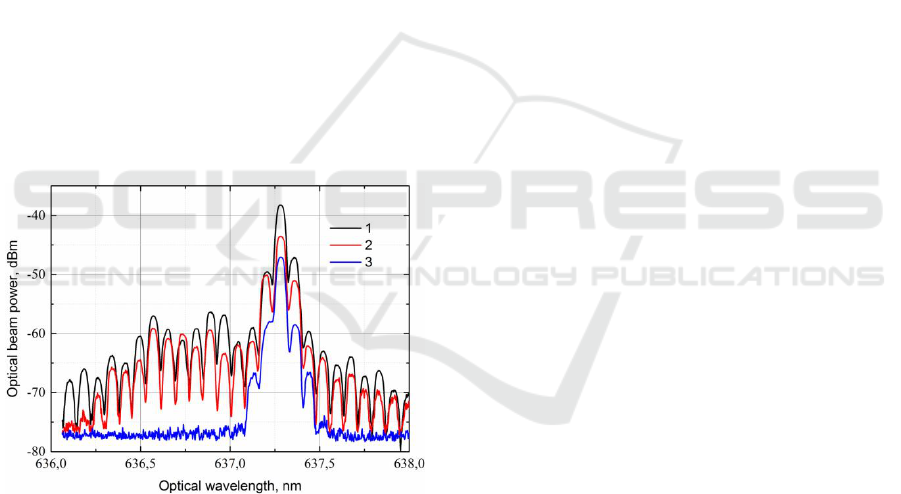
resolution. The results of this measurement are
illustrated by curve 1 in Fig.2.
The spectrum of the signal optical beam was
measured for two cases. In the first case the AO
system was operating without feedback like the
conventional collinear AO filter (curve 2) and in the
second case it was operating in the generation mode
(curve 3). It is known that the half-width of the AO
filter used in experiment without feedback is 0.9nm.
So we may notice the influence of the filter
transmission on the laser modes between 636 and
636.3 nm.
Figure 2: The measured optical radiation spectra. 1 -
ThorLabs CPS635R laser module spectrum; 2 – AO
system without feedback; 3 – AO system with feedback in
the generation mode.
In the generation mode the situation differs
completely, it is possible to say that the total
passband of the system is near 0.35nm, so the
system passband in the generation mode is much
narrower than for the same AO filer without
feedback.
The comparatively low AO diffraction efficiency
of the presented curves 2 and 3 is explained by low
power of the acoustic wave aroused in the AO cell.
The proposed AO demultiplexer applies the
operation in the generation mode with frequency
locking effect used for optical spectrum component
selection.
5 THE OPTICAL RADIATION
SPECTRUM CONTROL WITH
FREQUENCY LOCKING
5.1 Acousto-optic Demultiplexer
The most interesting application of the frequency
locking effect is to use it for the creation of the
acousto-optic demultiplexer. Let the optical input of
the system be fed with radiation containing several
discrete spectral components. In the experiment two
identical laser modules with a wavelength of
radiation near 655 nm were used to simulate such a
situation. The radio frequency spectrum analyzer
was used to register the spectral composition of the
electrical signal in the feedback circuit. The RF
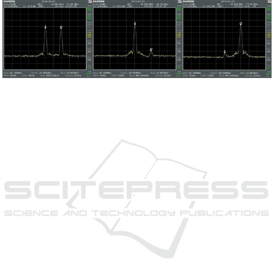
signal spectra observed in the feedback circuit with
this spectrum analyzer are presented in Fig.3. The
laser modules emitted at slightly different
wavelengths spaced 2.2 nm apart. Since the
intensities of the light beams were practically
identical the self-oscillations were excited in the AO
system at two frequencies, spaced 157kHz apart
(which corresponds to 2.2 nm by Eq. (1)) with
almost equal amplitudes (Fig. 3a).
Thus, there are two signals in the electrical
circuit and two acoustic waves were excited in the
AO cell, on each of which diffracts its own optical
wave, and light radiation from both lasers was
observed at the optical output of the AO system.
When the external RF generator is connected to
the system and tuned to an arbitrary frequency near
the AO system self-oscillations frequencies the
electrical signal in the feedback circuit will already
contain three spectral components - two frequencies
of the self-oscillations and one - forced at the
frequency of the RF generator. The RF signal power
and the feedback gain were selected so that the
locking effect bandwidth was less than the self-
oscillations frequencies difference. If the frequency
of the RF generator was chosen in such a way that
self-oscillations were locked at one of the
frequencies, then the oscillations at the second
frequency were suppressed (Fig. 3b, c). The
observed suppression factor was more than 42dB. In
this case the optical radiation on the AO system
output will contain only at one wavelength
Acousto-optic Time-Domain Optical Demultiplexer
33
(a)
(b)
(c)
Figure 3: The spectra of RF signal in the AO system feedback circuit; (a) – two optical waves on the AO cell input, AO
system is in the generation mode; (b) – low frequency self-oscillations are locked; (c) – high frequency self-oscillations are
locked.
corresponding to the locked self-oscillation
frequency. So this selection of the optical
wavelength by locking the RF frequency in the
feedback may be considered as the AO time domain
demultiplexing.
In the general case, in the presence of a large
number of discrete spectral components in the
optical signal, the number of selected components
will be determined by the RF signal spectrum
supplied from the external generator. As it is
possible to lock simultaneously several self-
oscillation frequencies.
Thus, using the effect of AO system self-
oscillations frequency locking it is possible to realize
the AO demultiplexer capable selection of one or
more spectral components of optical radiation. The
minimum spacing between the components that it
will be able to select will be determined by the
characteristics of the AO filter used (for the calcium
molybdate crystal with 4 cm AO interaction length,
the spectral interval between the components may be
less than 1 nm), the crosstalk attenuation between
adjacent channels will exceed 42 dB, the tuning rang
corresponds to the AO cell tuning range that is
usually not less than one octave.
5.2 System Operation Speed
Examination
Operation speed is an important parameter of
optoelectronic devices especially for the time-
domain demultiplexing devices. The processing
speed of this system is primarily determined by the
acoustic wave propagation time in the AO cell. The
AO filter used in the experiment was fabricated from
calcium molybdate with 4cm interaction length and
2.91∙10
5
cm/s ultrasound velocity, so it has the time
constant
μs. The examined AO
system operation speed depends on the value of the
feedback gain factor κ and its limiting value is .
It follows from the evaluations carried with
Eq.(12)-(13) that the higher is the gain κ, the faster
the system goes to the steady-state operation mode
with the constant amplitude of the RF signal in the
feedback circuit, acoustic wave in the AO cell and
light intensity on the output. Thus, if at κ = 6.7 (with
a threshold value κ = 6.35), the self- oscillations
establishment time is 410 μs, then if feedback gain
increases to κ = 8.9 this time decreases to 69 μs. At
the same time, the stationary amplitude of the self-
oscillations and consequently the AO diffraction
efficiency increases.
The minimum time for the stationary self-
oscillations amplitude establishment observed in the
experiment was 73 μs. At the same time, the 0.86
diffraction efficiency was achieved for the feedback
gain κ = 560 (the maximum possible diffraction
efficiency in the AO cell used is 0.92). The further
diffraction efficiency increase was limited by the
maximum attainable gain of the amplifiers used in
the feedback circuit.
6 CONCLUSIONS
The examination of the acousto-optic system
combining a collinear filter and a feedback circuit
was continued in this paper. The operation of this
system in the generation mode and the possibility of
system self-oscillations locking effect practical
application was studied. A new type of AO device
was proposed: an acousto-optic demultiplexer with
AO collinear filter as the core element.
PHOTOPTICS 2019 - 7th International Conference on Photonics, Optics and Laser Technology
34

It was shown that the total transmission
bandwidth of the system combining the collinear AO
filter and the feedback circuit in the generation mode
is much narrower than the half-width of the
transmission function of the same collinear AO filter
without feedback (0.35 nm to 0.9 nm).
A prototype of an acousto-optic demultiplexer
was considered. This device operates by using the
frequency locking of the AO system self-oscillations
by an external RF generator signal. It was shown
that when one or more of the system self-oscillations
frequencies are locked, the remaining frequencies
are suppressed, and only those optical radiation
wavelengths that correspond to the locked
frequencies remain on the optical output of the
system. In this case, the experimentally observed
crosstalk attenuation between adjacent channels
exceeds 42dB. The tuning range of the
demultiplexer equals to the tuning range of the AO
filter.
It was shown that the operation speed of the
examined system is determined by the feedback
gain, and its limiting value is equal to the acoustic
wave propagation time along the entire AO cell
length.
ACKNOWLEDGEMENTS
The work has been supported by the Russian
Science Foundation (RSF), project 18-72-00036.
REFERENCES
C.S. Sobrinho et. al, 2004, Numerical analysis of the
crasstalk on an integrated acousto-optic tunable filter
(AOTF) for network applications, Fiber and
Integrated Optics, 23, 345-363.
R. Ghannam, W. Crossland, 2005, Novel wavelength-
tunable optical filter for WDM applications, Proc.
SPIE, 6014, 60140V-1-10.
T. Kinoshita, K. Sano, E. Yoneda, (1986), Tunable 8-
channel wavelength demultiplexer using an acousto-
optic light deflector, Electronics Letters, 22(12), 669-
670.
J. Chrostowski, 1982, Noisy bifurcations in acousto-optic
bistability, Phys.Rev.A, , 26(5), 3023-3025.
V.I. Balakshy, Yu. I. Kuznetsov, S.N. Mantsevich, N.V.
Polikarpova, 2014, Dynamic processes in an acousto-
optic laser beam intensity stabilization system, Opt.
Laser Technol., 62, 89-94.
V.I. Balakshy, I.A. Nagaeva, 1996, Optoelectronic
generator based on the acousto-optical interaction,
Quant. Electron. 26(3), 254-258.
M.R. Chatterjee, M. Al-Saedi, 2011, Examination of
chaotic signal encryption and recovery for secure
communication using hybrid acousto-optic feedback,
Opt. Eng., 50, 055002.
S.N. Mantsevich, V.I. Balakshy, 2018, Experimental
examination of frequency locking effect in acousto-
optic system, Appl. Phys. B, 124:54, 1-17.
S.N. Mantsevich, V.I. Balakshy, 2018, Examination of
optoelectronic feedback effect on collinear acousto-
optic filtration, JOSA B, 35, 1030-1039.
S.E. Harris, S.T.K. Nieh, R.S. Feigelson, 1970, CaMoO
4
electronically tunable optical filter, Appl. Phys. Lett.
17(5), 223-225.
V.I. Balakshy, S.N. Mantsevich, 2007, Influence of the
divergence of a light beam on the characteristics of
collinear diffraction, Opt. Spectr., 103(5), 804-810.
V.I. Balakshy, Yu. I.Kuznetsov, S.N. Mantsevich, 2016,
Effect of optoelectronic feedback on the characteristics
of acousto-optical collinear filtering, Quant. Electron.,
46( 2), 181-184.
S.N. Mantsevich, V.I. Balakshy, Yu.I. Kuznetsov 2016,
Effect of feedback loop on the resolution of acousto-
optic spectrometer, Phys. of Wave Phen. 24(2), 135-
141.
S.N. Mantsevich, V.I. Balakshy, Yu.I. Kuznetsov, 2017,
Acousto-optic collinear filter with optoelectronic
feedback, Appl. Phys. B, 123:101, 1-8.
V.I. Balakshy, I.M. Sinev, 2004, Mode competition in an
acousto-optic generator, J. Opt. A Pure Appl. Opt.,
6(4), 469-474.
S.E. Harris, R.W. Wallace, 1969, “Acousto-optic tunable
filter”, J. Opt. Soc. Am., 59(6), 744-747.
V.I. Balakshy, S.N. Mantsevich, 2009, Influence of light
polarization on characteristics of a collinear
acoustooptic diffraction, Opt. & Spectr. 106(3), 441-
445.
V.I. Balakshy, S.N. Mantsevich, 2012, Polarization effects
at collinear acousto-optic interaction, Opt. & Laser
Techn. 44(4), 893-898.
Acousto-optic Time-Domain Optical Demultiplexer
35
