
Resolving the Asymmetry of On-Exit versus On-Entry in Executable
Models of Behaviour
Vladimir Estivill-Castro and Ren
´
e Hexel
School of ICT, Griffith University, Nathan Campus, Nathan 4111, Australia
Keywords:
Executable UML, UML State Charts, Model-based Testing and Validation, Modelling Behaviour.
Abstract:
For the UML, state charts are by far the most used modelling tools, both to communicate behaviour and to
produce executable models. We investigate the inherent asymmetry of On-Entry and On-Exit Actions in UML
Statecharts. We show first that the apparently simple and symmetric rules for handling the sequencing of
On-Entry and On-Exit actions are hard to fully comprehend and apply effectively by software developers.
Second, defining a semantics that results in executable models for applications such as reactive-systems and
real-time systems is very delicate. Third, formal verification can be hampered because the semantics results
in a combinatorial explosion of states. We evaluate the understandability of the semantics by taking out
experiments with various tasks comprising sample UML Statechart and logic-labelled finite state machines
(LLFSMs). Several experiments with software developers enable us to dissect how issues of understandability
of state diagrams relate to nesting or event-driven vs logic-labelled. Since logic-labelled finite state machines
achieve model composition through a subsumption architecture (suspend/restart/resume) we propose a specific
alternative semantics for logic-labelled finite state machines that is suitable for robotic and embedded systems.
1 INTRODUCTION
Wikipedia is the source of information for billions
of people on the planet. Its English version records
more than 20 billion views per month. Wikipedia’s
page on UML state machines
1
declares that “every
state in a UML state chart can have optional entry
actions, which are executed upon entry to a state,
as well as optional exit actions, which are executed
upon exit from a state. Entry and exit actions are
associated with states, not transitions. Regardless
of how a state is entered or exited, all its entry and
exit actions will be executed.” Moreover, the impli-
cation is that the On-Entry and On-Exit sections of a
state are shorthand notation for what otherwise would
be the cumbersome inclusion of more states. Even
more importantly, they are treated symmetrically as
set-up and tear-down phases: The value of entry and
exit actions is that they provide means for guaran-
teed initialization and cleanup, very much like class
constructors and destructors in Object-oriented pro-
gramming.” Thus, one can assume that the On-Entry
and On-Exit sections are some form of notational sim-
plification for potential pre-states and post-states (see
1
en.wikipedia.org/wiki/UML state machine
Figure 1). The situation is not much different with
fUML (a subset of the standard Unified Modelling
Language (UML) for which standard, precise execu-
tion semantics are provided). Although fUML uses
Clause 15 of the UML Superstructure to define the ex-
ecution semantics for statecharts, it describes the en-
try behaviour and the exit behaviour of a state in com-
pletely symmetric terms when it describes Alf (Ob-
ject Management Group, 2017, Page 328). We argue
here that there are profound implications for the se-
mantics of these UML forms, both for understand-
ability of UML diagrams and for correctness, vali-
dation and formal verification of executable models.
Among practitioners, a top criterion for the adoption
of UML’s representation is whether such representa-
tions are understandable (Petre, 2013). Professional
software developers’ largest gripes are around com-
plexity and lack of formal semantics (Petre, 2013).
Little would be achieved without some form of
model composition. The subsumption architecture
enables layers of timed logic-labelled finite-sate ma-
chines to structure more sophisticated behaviours on
top of simpler behaviours (Brooks, 1986). The UML
proposes orthogonal regions (Samek, 2008, Chap-
ter 2) (so-called AND-decomposition, which also im-
plies concurrency) and nesting sub-states (so-called
Estivill-Castro, V. and Hexel, R.
Resolving the Asymmetry of On-Exit versus On-Entry in Executable Models of Behaviour.
DOI: 10.5220/0007323300490061
In Proceedings of the 7th International Conference on Model-Driven Engineering and Software Development (MODELSWARD 2019), pages 49-61
ISBN: 978-989-758-358-2
Copyright
c
2019 by SCITEPRESS – Science and Technology Publications, Lda. All rights reserved
49

later
state 2
later
state 1
earlier
state B
complex state
On-Entry : do action_s
On-Exit : do action_t
Do: action_u
earlier
state A
e4
e3
e1
e2
(a) Typical state with On-Entry and On-Exit sections.
On-Exit
do action_t
Internal
do action_u
On-Exit
do action_t
On-Entry
do action_s
later
state 2
later
state 1
earlier
state B
earlier
state A
e4
e3
e1
e2
(b) Equivalent On-Entry and On-Exit behaviour.
Figure 1: On-Entry and On-Exit as intermediate states.
OR-decomposition). Nested states have been la-
belled “great diagrammatic simplifications when a
set of events applies to several sub-states” (Douglass,
1999) Some (Samek, 2008, Page 69) regard hierarchi-
cally nested states by Harel and Politi (1998), as the
most important invention. However, Mellor (2000)
noted several issues and complex semantic implica-
tions. Similarly to the Ultimate Hook Pattern, nested
states are a mechanism to produce common facili-
ties and simplification to event-handling policies. The
sharing of behaviour through a notation that implies
inheritance is very powerful and widely used in many
aspects of object-orientation and the UML in particu-
lar. This abstraction capacity mostly follows Liskov’s
Substitution Principle (Liskov and Wing, 1994) and
implies that a sub-state of a composite state has be-
havioural inheritance. However, in the case of states,
the is a relationship of inheritance is replaced by is
in (is-in-a-state) relationship (Samek, 2008, Page 72).
Consider Figure 2.
2
Here, the system in the toasting
state is-in the heating state.
We have carried out a series of experiments on
the understandability of two particular issues in UML
diagrams. First, the asymmetry of On-Entry actions
versus On-Exit actions (which is already present in
Figure 1, because On-Exit actions require an addi-
tional implicit state per transition). Second, the com-
plexity of state-nesting. Our results are complemen-
tary to several of studies on the understandability of
UML state charts, but we stress here the theoretical
and experimental validation of metrics (Genero et al.,
2003) such as NEntryA (number of entry actions),
NExitA (number of exit actions), and NCS (number
of composite states). In previous work, these
three metrics (NEntryA, NExitA, and NCS), al-
though theoretically validated and inspired by the lit-
2
Figure 2 (Samek, 2008, Figure 2.7) appears in
Wikipedia’s page on UML state machines and is distributed
as commons material; we also used it on our experiments.
Figure 2: A sample UML state chart.
erature, have experimentally been shown not to be
correlated with the understandability of UML dia-
grams (Genero et al., 2003). Our results indicate
that NEntryA (number of entry actions) and NExitA
(number of exit actions) are indeed relevant for under-
standability of a state diagram. The first set of metrics
experimentally correlated to the understandability of
UML state diagrams were NA (number of activities),
NSS (number of simple states), NT (number of tran-
sitions), and NG (number of guards) (Genero et al.,
2003). However, as the results were non-conclusive,
further research followed (Cruz-Lemus et al., 2005,
2009). We still believe that those other metrics are rel-
evant to the understandability of UML state diagrams.
However, we emphasise new aspects, the asymmetry
of the On-Entry and the On-Exit actions, the event-
driven nature of UML vs the deterministic execution
of logic-labelled finite-state machines (LLFSMs), and
naturally the nesting mechanism for composition. We
note again that, although abstraction and understand-
ability had been heralded for nesting states, this was
not so evident in experimental settings (Cruz-Lemus
et al., 2005, 2009). Our point here is that the issues
of nesting, and the asymmetry of On-Exit versus On-
Entry have been neglected from detailed analysis.
We show that the apparently simple and symmet-
ric rules for handling the sequencing of On-Entry and
On-Exit actions represent a series of fallacies. First,
these rules are very hard to comprehend and to apply
by software developers, especially when timing issues
and composition are involved. Second, defining a se-
mantics that results in executable models for applica-
tions such as reactive systems and real-time systems is
very delicate. Third, verification is hampered because
the semantics results in a combinatorial explosion of
states. We derive these conclusions from several ex-
periments with software developers and dissect how
issues of understandability of state diagrams relate to
nesting, or event-driven vs logic-labelled. Since LLF-
SMs achieve model composition through a subsump-
tion architecture (suspend/restart/resume) we propose
a specific alternative semantics for LLFSMs that is
suitable for robotic and embedded systems.
UML state charts are ubiquitous and it has been
documented they, along with class diagrams, are one
of the top used artefacts (Reggio et al., 2013). They
MODELSWARD 2019 - 7th International Conference on Model-Driven Engineering and Software Development
50

have very strong penetration in embedded systems,
and are even used as executable models, synthesising
VHDL (Wood et al., 2008). Nevertheless, UML state
charts remain the subject of strong criticism (Rumpe,
2002; B
¨
orger et al., 2000; Glinz, 2000; Reggio et al.,
2000). On one hand, the criticism is accurate regard-
ing the ambiguous semantics, but on the other hand,
UML is best used at the conceptual level. In any case,
we found usability studies rarely support such crit-
icism. The issue of understandability is subject of
some studies we review in the next section.
2 UNDERSTANDABILITY
How useful is UML? Experimental studies have con-
firmed that visual and textual standard notations en-
able communicating software designs to stake hold-
ers. Moreover, UML can be cost-effective, as shown
by Dzidek et al. (2008), who evaluated the cost of
using UML at a degree of formality that is realis-
tic for being a reflection of the running code. The
study involved 20 senior developers (10 with UML
experience) on five realistic maintenance tasks that re-
quired between 1 to 2 weeks. As a secondary goal,
this study identified plausible and necessary condi-
tions for UML to be effective. One of the assets of the
study was that subjects were experienced developers.
Nevertheless, a one day UML refresher was offered to
all participants to level the experience. The study only
considered class diagrams and sequence diagrams and
concluded that expertise with UML and usability of
associated tools are strong influencing factors in the
cost-effectiveness of using UML.
Along the same lines are studies on UML’s use-
case templates. Mustafa (2010) discusses the impor-
tance of the human dimensions in understandability of
modelling UML artefacts, as these are the main com-
munication vehicle between all stake holders, includ-
ing developers. Once again, the usability is linked to
simplicity; UML artefacts must be intuitive to under-
stand to be successful (Mustafa, 2010). Although fo-
cussed on use-case templates and diagrams, Mustafa
(2010) reviewed previous UML comprehension stud-
ies, noting a focus on class diagrams (structural de-
scriptions), sequence diagrams, and stereotypes.
UML diagram understandability is related to cog-
nitive load; and thus, inexperienced users struggle
with diagrams that require heavy, intrinsic cognitive
load correlating with diagram details (Mustafa, 2010).
Mustafa (2010) used the following definition of un-
derstandable: “The use case model is understandable
if it allows users to recognise problem domain in-
formation and extend their understanding in problem
solving.” Therefore, Mustafa (2010) recommends that
for evaluating understandability, besides question ac-
curacy, experimenters shall evaluate the time required
to answer the question. “understanding is a cognitive
process, [and] it is difficult to directly observe it, and
tests to measure participants’ performance were con-
ducted to assess the level of understanding cognitively
developed by each participant.” (Mustafa, 2010).
Understandability of UML state charts has been
the focus of Cruz-Lemus et al. (2005, 2009). The
research on the comprehension of state charts com-
menced with theoretical and experimental studies of
the features that raise interpretation difficulty (Gen-
ero et al., 2003). Composite states add comprehen-
sibility when users have prior familiarity with their
features (Cruz-Lemus et al., 2005), but counterintu-
itively, no direct link between composite state com-
plexity and UML state chart understandability was es-
tablished. The hypothesis is that the use of compos-
ite states provides simplification, and then enhances
understandability; but this hypothesis is not true for
inexperienced users (Cruz-Lemus et al., 2005).
We hypothesise that users find UML state charts
hard to understand because their nesting usually im-
plies uncontrolled concurrency. That is, nesting
of states, although simply described (see Wikipedia
quote earlier), implies complex rules to resolve the
sequence of execution. As such, we believe that logic-
labelled finite-state machines (LLFSMs) are more un-
derstandable. There is some justification for this
hypothesis. LLFSMs execute under a deterministic
schedule. Previous work with formal verification and
model checking with LLFSMs (Estivill-Castro et al.,
2012) demonstrates that LLFSMs avoid the exponen-
tial explosion of associated Kripke structures used as
input to model checkers. By contrast, UML state
charts are event-driven, requiring a complex event
handling process of at least five sub-steps.
Event Generation: All generated events must be
channelled to those state charts whose transitions
wait for the event.
Event Conveyance: Events are transported to cur-
rent objects and states, theoretically with no delay
and without changing the event.
Event Reception: Events are placed on queues, typ-
ically one queue per state chart (Samek, 2008).
Event Dispatch: The current event is de-queued,
activating all responders as per the Run-Until-
Completion semantics (Samek, 2008).
Event Consumption: Indicates that the event has
been handled; in some cases, removal from the
queue is just part of this step (Samek, 2008).
Resolving the Asymmetry of On-Exit versus On-Entry in Executable Models of Behaviour
51

This mechanism implies call-backs associated with
the corresponding events. As the fundamental as-
pect of the Hollywood principle, it is often viewed
favourably and used in many software patterns to min-
imise coupling. However, callback order of execution
becomes unpredictable, requiring a model checker
to evaluate all paths of execution. Formal verifica-
tion must consider all possible orders in which events
may be queued, despite such combinatorial explosion.
The semantics of hierarchically nesting of states in
UML is commonly specified with an interlingua ap-
proach. Namely, a construct is considered a short-
hand notation for a larger construct in the language
or another language for which the semantics has been
provided. For hierarchically nesting, “the Cartesian
product machine is used as the interlingua semantics
of state charts” (Drusinsky, 2006, Page 63). More-
over, “an event can trigger a transition in all active
threads, in some action threads, or in none” (Drusin-
sky, 2006, Page 63). UML users must keep in mind
all aspects of the event-driven Run-Until-Completion
semantics and the nested state interlingua semantics
(cognitive load).
By comparison, LLFSMs use two fundamental
approaches as key composition mechanisms.
Status/Control Message Passing: Orthogonal
behaviours with different responsibilities can syn-
chronise through a shared memory reader/writer
architecture that avoids race conditions.
Using Mechanisms to suspend/resume/restart:
Enabling all sorts of machine hierarchies; in
particular, allowing subsumption architectures.
In this paper, we experimentally evaluate the hypoth-
esis proposed.
3 METHOD
We performed several controlled experiments and
their replication under Griffith University Ethics Ref-
erence Number: 2018/785. Subjects with software de-
velopment and software modelling experience were
either 1) randomly divided into two or three groups
for different tasks or 2) observed with respect to two
or three different features on the same task. We al-
ways recorded the time to complete the task.
Our experiments consisted of formulating a hy-
pothesis, such as “use of composite states improves
understandability of UML” and then used a measure
that considers how quickly subjects solve a task and
how accurately they solve the task. The measure we
used is “understandability efficiency” (Cruz-Lemus
et al., 2005) as the accuracy (the number of correct
answers) divided by the time taken. We completed
the experimental formulation by defining a hypothe-
sis testing scenario; for example:
H
0
: the use of composite state diagrams does not im-
prove the understandability efficiency.
H
1
: the use of composite state diagrams does im-
prove the understandability efficiency.
3.1 Experimental Process
The experiments took place in Queensland, Australia,
during July and August 2018. The subjects were stu-
dents of Griffith University from two campuses and
four different degrees (one master and three under-
graduate programs). Besides subjects being students,
other aspects in common with earlier UML under-
standability studies (Cruz-Lemus et al., 2005; De Lu-
cia et al., 2010; Genero et al., 2003) were as follows.
1. The tasks in the experiment did not require a high
level of industrial experience.
2. Students were in their final year, completing a
course in software engineering, or they were mas-
ters students who had already completed a prior
IT degree.
3. Subjects received significant instruction on the
main constructs of the UML. Model-Driven de-
velopment was illustrated and exercised in labo-
ratories using ARGO-UML (Robbins, 1999).
4. Students developed UML class diagrams and gen-
erated code in C++, Java and SQL, analysing mul-
tiple aspects of the mappings.
5. State charts were used in laboratories using
model-driven development and executable mod-
els through the QM
TM
tool. Students were re-
quired to review “A Crash Course in UML State
Machines” distributed by Quantum
R
L
e
aPs
3
and
based on (Samek, 2008, Chapter 2).
6. Subjects, therefore, had similar expertise as in the
literature and were given similar motivation, such
as explaining that the tasks would be illustrative of
the final exam (Cruz-Lemus et al., 2005; De Lucia
et al., 2010; Genero et al., 2003).
7. As part of the experimental procedure, prior to at-
tempting the tasks, subjects were given the oppor-
tunity to review material on UML state charts, e.g.
the above Wikipedia page, plus two others
4
.
3
https://www.state-machine.comstate-machine.com
4
https://www.uml-diagrams.org/state-machine-diagra
ms.htmland https://www.lucidchart.com/pages/uml-state-
machine-diagram
MODELSWARD 2019 - 7th International Conference on Model-Driven Engineering and Software Development
52

In experimental software engineering, when subjects
face relatively small tasks, only minor differences be-
tween professionals and students are expected (Basili
et al., 1999; H
¨
ost et al., 2000). Thus, we also adopt
the common assumption that our students as subjects
are appropriate (Cruz-Lemus et al., 2005; De Lucia
et al., 2010; Genero et al., 2003).
3.2 Experimental Design
We conducted several of two types of experiments in
different weeks, with voluntary participation.
Same Treatment of All Subjects: Evaluation of
two or more aspects of the subject’s performance.
Everyone solved the same problem, then a
correlation analysis was performed. E.g., all
subjects are to describe all diagram features and
we measure the accuracy of describing On-Entry
behaviour versus describing On-Exit behaviour.
Different Treatments of Subjects: All subjects an-
swered the same questions about different, ran-
domly assigned diagrams, and an ANOVA (or t-
test, if two classes) was performed. Groups were
randomly assigned, and all were asked to com-
plete the same task; however, each group pro-
ceeded with diagrams with a specific feature (for
example state nesting) with the control from a di-
agram without the feature.
3.3 Experimental Tasks
All tasks consisted of the interpretation of simple
UML diagrams (comprising of at most three levels of
nesting, typically two, and at most one machine and
one sub-machine). Typically, the notation had been
presented earlier. For models that produced short out-
put, subjects were asked to anticipate the output gen-
erated. For behaviours that generated continuous out-
put, subjects were required to identify the main traits
of the behaviour, or alternatively subjects we asked
whether a particular sequence of output statements
occurred in that precise order.
Experiments were conducted as extra-laboratory
exercises within the context of a third-year Software
Engineering course. Responses were anonymous;
thus, students were not evaluated on their individual
performance. We followed De Lucia et al. (2010) in
selecting easy to comprehend data models. The sub-
jects were not aware of any of our scoring approaches
or metrics of interest, and they were allowed plenty of
time to complete the task. We emphasised the premise
that a simple data model was preferred over a more
complex one (as the focus was not the application do-
main nor the accuracy with which the model reflects
complex situations). The attention of our research is
the notation used to represent the diagram (De Lucia
et al., 2010). We also emphasise that for understand-
ing tasks (and the understandability of UML artefacts)
it is common to request subjects to provide as much
information as possible and to define the expected re-
sponse prior to issuing the task.
3.3.1 Calibration
Our first experimental task was the verbatim reuse of
the original Questionnaire of Appendix A by Cruz-
Lemus et al. (2005), and randomly partitioning the
subjects to answer the Questionnaire with respect to
the original Figures 5 (F5) and 6 (F6) (Cruz-Lemus
et al., 2005), We remark that the task could be con-
sidered particularly simple, and unfortunately (Cruz-
Lemus et al., 2005, Figure 5) or (Cruz-Lemus et al.,
2005, Figure 6) may be translations from Spanish to
English (the figures have a spelling error). Each figure
is supposed to have an equivalent UML diagram that
models the same behaviour of a phone call: F5 uses
nesting states while F6 has no nested states. How-
ever, F6 is a simplified version of F5 (recall the inter-
lingua semantics of nested states). That is, F6 draws
much fewer transitions than those implied by F5. This
difference demonstrates that indeed, nesting exposes
many transitions that, if drawn, would clutter the dia-
gram (perhaps unnecessarily so).
Importantly, the figures are not semantically
equivalent. Nevertheless, the questions in the Ques-
tionnaire (Cruz-Lemus et al., 2005, Appendix A) do
not explore this issue.
3.3.2 Simple, Nested Model
Our second experimental task consisted of predict-
ing the output of a simple model, in particular, to
comprehensively describe the information provided
by the UML state chart in Figure 2. For this task,
the prepared answer was to obtain paragraphs equiv-
alent to those in Figure 3. Also a questionnaire that
had 8 questions testing subjects on whether they could
correctly identify behaviour (sequencing) on On-Exit
conditions, On-Entry conditions, On-Entry and On-
Exit conditions, Run-Until-Completion, State Nest-
ing, ordering of events, ordering of nesting (prior-
ity on exiting a hierarchy of nested states), and re-
entering a hierarchy of nested states.
3.3.3 Non-nested LLFSM
In the third task, we used the downloadable version
5
of the clfsm scheduler for logic-label finite-state ma-
5
www.mipal.net.au/downloads.php
Resolving the Asymmetry of On-Exit versus On-Entry in Executable Models of Behaviour
53

(2 points: state chart and composite states/sub-states) This diagram models the behaviour of some device that has fundamentally two states: heating
and door open. The heating state has sub-states toasting and baking. Because of the solid-dot pseudo-states, this device starts in the heating
state, and in the toasting sub-state. Separate states are exclusive, so the system is either in the heating state or the door open state. Similarly, the
system is either toasting or baking. However, sub-states occur within their parent state; for example baking happens always while heating.
(1 point: transitions labelled by events) An event CLOSE DOOR will transition the system from the state door open to heating.
(1 point: when On-Entry and On-Exit happens) An event DOOR OPEN will cause the system to move from heating to door open no matter what sub-
state in heating. When we leave heating in this case, the action heater off will be performed as an exit activity of the state heating followed by
the action internal lamp on which is the entry activity of the state door open. Here we see two actions where one happens before the other.
(1 point: nesting is described) The transitions between heating and door open are both external transitions, but the transition of the events DO BAKING
and DO TOASTING are internal transitions. So when DO BAKING, no matter the sub-state in heating, we will come to the sub-state baking, but we will
not execute the exit of heating, we will execute the exit of toasting (if we were in toasting, that is the action disarm time event is performed
but heater off is not. However, the action set temperature of baking is performed after as the entry to baking. Every time the system goes out of
toasting the disarm time event is executed. Similarly, departing form baking always executed the action set temperature.
Figure 3: Expected point we believe should not be lost in translation where interpreting the model of Figure 2 in English.
chines and the MiEdit editor under Ubuntu 16.04
and ROS-Kinetic (we did not implement the message
passing approach for communicating LLFSMs, but
used rostopics and rosservices from ROS’ mid-
dleware). Subjects were provided practice in execut-
ing LLFSMs with the clfsm scheduler.
For the task, subjects were required to predict the
output of the logic-labelled finite-state machine in
Figure 4. This apparently simple model has impli-
cations for understanding the notion of guards, when
in a ringlet is a transition evaluated, and whether the
On-Exit is executed in a final state.
3.3.4 Nested LLFSMs
For the fourth task, the setting again was the exe-
cutable model defined by an LLFSMs and the en-
vironment was the clfsm scheduler and communi-
cation with ROS-Kinetic middleware. In prepara-
tion for this task, the clfsm scheduler capabilities to
suspend/resume/restart one LLFSM from another
LLFSM were demonstrated. Although the executable
model produces continuous output, the task consisted
of formulating a qualitative prediction of the execu-
tion of the LLFSM in Figure 5.
3.3.5 Subsumption and Delegation
For the preparation of the fifth task, we provided
examples of message passing using the ROS pub-
lisher/subscriber software pattern (rostopics) and
the client/server software pattern (rosservices). Be-
cause LLFSMs do not use callbacks, instructions
were provided on wrapping signals (events) in a
rostopic into a rosservice (as illustrated by the
third example of the downloadable ROS LLFSM ex-
amples for ROS on the above download site).
In this task, subjects were required to implement
the model presented in Figure 2 using LLFSMs; in
particular, the behaviour that responds to the signals
to bake and to toast; then to construct a second
behaviour that responds to the signals open door
and close door, and finally to integrate the two be-
haviours. Subjects were required to commit to one of
the two strategies by which LLFSMs represent nest-
ing of states: that is, subjects were asked to chose
between suspend/resume/restart or to use a dele-
gation (forwarding) of messages.
3.3.6 Randomised Diagrams
In the sixth and final experiment, subjects were ran-
domly partitioned into three groups and provided the
same Questionnaire (Figure 6). However, each group
was provided with a different diagram. The first group
was provided the diagram in Figure 2, while the sec-
ond was provided with a model solution to its im-
plementation using suspend/resume/restart with
LLFSMs, the third was provided with a model solu-
tion using delegation/forwarding with LLFSMs.
3.4 Replication
All experiments were replicated between two cam-
puses with common offerings of the same course,
but different staff (lecturers, instructors, and tutors).
Also, each campus had an additional, specific pro-
gram not offered at the other (Computer Science and
Software Engineering), with some overlap (IT).
4 RESULTS
We now report on the experiments described earlier
and detail the perception and understandability of the
different models.
MODELSWARD 2019 - 7th International Conference on Model-Driven Engineering and Software Development
54
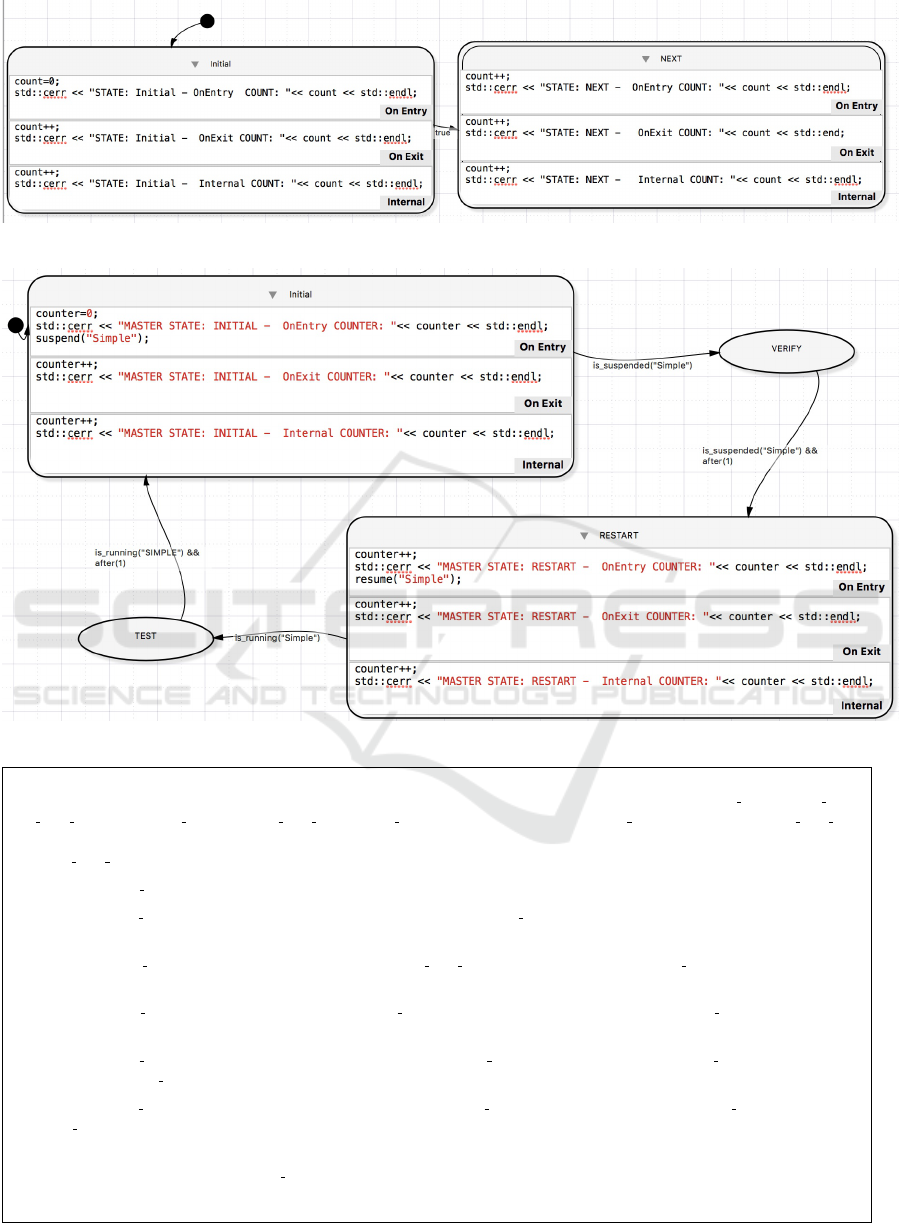
Figure 4: A simple logic-labelled finite-state machine.
Figure 5: A logic-labelled finite-state machine that affects another LLFSM.
The diagram models the behaviour of a toaster oven. Assume that no events have been issued prior to each of the questions below, and that the two
behaviours were launched concurrently in the order Outer followed by Inner. Answer only in terms of the actions: heater on(), heater off(),
arm time event(me->toast color), disarm time event(), set temperature(me->Temperature), set temperature(0), internal lamp on(),
and
internal lamp off().
1. If the event to DO BAKING is received, what is/are a/the sequence of actions produced by all behaviours involved?
2. If the event to DO BAKING is received; and later, after a few seconds, the event to DOOR OPEN happens, what is/are a/the sequence of actions produced
by all behaviours involved?
3. If the event to DO BAKING is received, and while the action disarm time event() is being performed, the DOOR OPEN happens, what is/are a/the
sequence of actions produced by all behaviours involved?
4. If the event to DO BAKING is received, and while the action set temperature(me->Temperature) is running the DOOR OPEN happens, what is/are
a/the sequence of actions produced by all behaviours involved?
5. If the event to DO BAKING is received, and after a few seconds the event to DOOR OPEN happens, and while the action set temperature(0) is being
performed, the DOOR CLOSE happens, what is/are a/the sequence of actions produced by all behaviours involved?
6. If the event to DO BAKING is received, and after a few seconds the event to DOOR OPEN happens, and while the action heater off() is executing, the
DOOR CLOSE happens, what is/are a/the sequence of actions produced by all behaviours involved?
7. Write down the minimum sequence of events and conditions needed, to go from the state toasting to the state baking, and back to toasting, but this
going back is not caused by an event to DO TOASTING:
8. Write down the minimum sequence of events and conditions needed, to go from the state toasting to the state baking, and back to toasting.
Figure 6: Questionnaire related to equivalent diagram and including Figure 2.
Resolving the Asymmetry of On-Exit versus On-Entry in Executable Models of Behaviour
55

4.1 Calibration
The replication of the Questionnaire by Cruz-Lemus
et al. (2005), Appendix A, shows no evidence of a dif-
ference between nested and plain diagrams. Our ex-
perimental outcome is equivalent to the results Cruz-
Lemus et al. (2005) reported. On the two cam-
puses we had 18 and 20 subjects respectively, each
equally divided into the two groups (nested versus
plain). This calibration enabled us to judge the under-
standability efficiency. There seems to be no signifi-
cant improvement (or difference) in understandabil-
ity/efficiency by using nested states. We offer here
a new explanation derived from our earlier observa-
tions and still congruent with the original conclusions
by Cruz-Lemus et al. (2005). Nested states are an
advanced concept. No-one would use introductory
state charts with nested states (not even the earlier-
mentioned crash course on UML state charts does
such a thing), as nested states represent a significant
cognitive load (and indeed an innovation and contri-
bution by Harel, as also mentioned before). But users
reach command of this artefact when experience and
regular usage assimilates the implicit semantics that
the interlingua semantics implies. Users (in the most
Piagetian constructivist style) must form and adapt
their conceptual frameworks to efficiently operate the
potential combinations implied by nested states.
4.2 Simple, Nested Model
Our first remarkable result is the score difference
observed for subjects answering questions regarding
On-Exit actions vs On-Entry actions on the same di-
agram. Our questionnaires had 8 questions: a correct
answer provided one point, an incorrect resulted in a
negative point. For each subject, we subtracted their
score for the On-Exit answer from the score for the
On-Entry answers. The null hypothesis was that the
mean of these differences is 0. For our first campus
experiment, with N = 51 respondents, the mean of the
difference scores was 3.00 with a standard deviation
of 3.85. The standard error of the mean was 0.54. A
t-test with 50 degrees of freedom rejects the null hy-
pothesis (p-value less than 0.00001). The replication
at the second campus had only N = 26 respondents;
nevertheless, the mean of the score differences was
2.11, with a standard deviation of 3.97. This results
in an estimate of the standard error for the mean of
0.41 and the t-test with 25 degrees of freedom also re-
jects the null hypothesis (p-value less than 0.00001).
Thus, our experimentation reveals that subjects have
different capacity to answer symmetrical questions re-
garding On-Entry sections of state charts as opposed
to On-Exit sections. The mean accuracy is higher for
the On-Entry questions than the On-Exit questions.
4.3 Non-nested LLFSM
The notion of logic-labelled finite-state machines
(LLFSMs) could be seen as UML models with no
events and only guards. Drusinsky (2006) consid-
ers LLFSMs under the name of procedural state ma-
chines, and he acknowledges that in that case, the
model is not at the mercy of the arrival of events:
“because [the automaton] can access the input sym-
bols at any time, it can visit states as fast as we
wish” (Drusinsky, 2006, Page 15).
Note that the notion of guard is typically intro-
duced with a discussion that UML state charts are
extended state machines (Samek, 2008, Chapter 2).
In LLFSMs, since there are no events, exactly when
the Boolean condition is evaluated is an important as-
pect of their precise semantics (a snapshot of all exter-
nal variables is taken before commencing of a ringlet,
and all guards of all transitions are evaluated in this
context). For UML, this issue is somewhat ambigu-
ous, the expressions are meant to be evaluated upon
the arrival of the event, but since, in executable mod-
els, events are queued, guards are evaluated during
the dispatching of the event (Samek, 2008, Chapter 2)
(recall the sub-steps to handle an event in Section 2).
Therefore, understandability of logic-labelled
finite-state machines (although completely sequen-
tial), seems also to require a certain level of maturity
and familiarity with UML (as we mentioned in earlier
sections, most experimental evaluations of artefacts
and cost-effectiveness of the UML suggest expertise
and significant familiarity are required). Our results
are consistent with this. We evaluated the understand-
ability/efficiency of the subjects as the accuracy of
questions about the LLFSM terminating (or running
in a continuous loop), whether the execution leaves
the state named Initial without executing the Do (In-
ternal) section, and whether the On-Exit of the NEXT
state is executed because no transition fires. There-
fore, a fourth element is that, when in state NEXT
the Do does run. We had 21 respondents on our first
campus, 10 graduate students and 11 undergraduate
students. The accuracy divided by the time taken
is used as understandability/efficiency and the values
satisfy a normal distribution assumption with a Q-Q
plot (for each group). The graduate students’ mean
understandability/efficiency is superior to that of the
undergraduate students (statistically significant at a
γ = 95% confidence level). Upon replication on the
other campus, we had 6 undergraduate volunteers and
12 graduate volunteers. Despite the lower numbers,
MODELSWARD 2019 - 7th International Conference on Model-Driven Engineering and Software Development
56
we also saw a significant result (at γ = 95%), show-
ing a superior understandability/efficiency for gradu-
ate students over the mean for undergraduate students.
4.4 Nested LLFSMs
We assessed the understandability/efficiency, evalu-
ating the subjects’ accuracy when the two LLFSMs
(Figure 4 and Figure 5) are placed in different initial
order in the execution arrangement. This swapping of
the initial conditions modifies the schedule slightly,
and the output varies. Moreover, in this case, the ex-
ecution continues endlessly. Our results indicate a
similar pattern as previously. The first campus had
14 undergraduate and 10 graduate students, the sec-
ond campus had 10 undergraduate and 11 graduate
respondents. Performance was significantly superior
for graduate students at γ = 95%. The undergraduate
students seem to follow each LLFSM separately. But
these subjects could not master the notion of ringlet
(and of round-robin schedule of the concurrent execu-
tion of the two LLFSMs) with the same understand-
ability/efficiency of the graduate students.
4.5 Subsumption and Delegation
All groups of students, in this case, opted for the
incorrect implementation pattern. The result is that
none of the subjects obtained a correct implementa-
tion with LLFSMs of the model in Figure 2.
4.6 Randomised Diagrams
Here we used first a 3-factor ANOVA (between sub-
jects / one-way) analysis, as we identify the three
types of diagrams. If we measure the accuracy on the
8 questions in Figure 6 divided by time, we find no
evidence that the means are different.
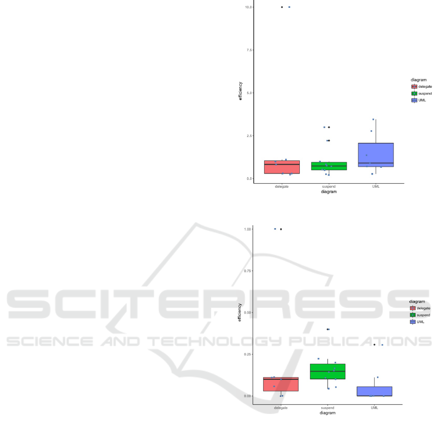
The box-plot in Figure 7 (generated with R’s
ggplot (R Core Team, 2016)) shows not much dif-
ference, except for one outlier where one subject did
extremely well for the LLFSM diagram using the del-
egation pattern. However, if we break the question-
naire into the four middle questions (3, 4, 5, and 6,
which deal with Run-Until-Completion semantics),
we obtain that the results are significantly better for
understandability/efficiency for diagrams with sus-
pend/resume (refer to Figure 8).
Conversely, on Questions 1, 2, 7, and 8, the UML
diagram performs much better. Again, the 3-factor
ANOVA results show no statistically significant dif-
ference. However an unpaired (two sample) t-test of
the understandability/efficiency on the UML diagram
versus the suspend/resume diagram does indicate the
Figure 7: Box plot of the 3-ways understandabil-
ity/efficiency per model type of the Figure 6 questions.
Figure 8: Box plot of the 3-ways understandabil-
ity/efficiency per model type on Q’s 3 to 6 for Figure 6.
rejection of the null hypothesis at 95%. That sug-
gests UML diagrams are understandable as long as we
set up scenarios with well-spaced events, where users
can follow all the consequences of one event before
the arrival of another. LLFSM seems to be the other
way around. While, at a first glance, this run-until-
completion semantics appears obvious and straight-
forward, in our experimental task with Figure 2 and
Figure 6, almost all subjects had substantial trouble
with Questions 4 to 8.
Resolving the Asymmetry of On-Exit versus On-Entry in Executable Models of Behaviour
57

5 DISCUSSION
As in many controlled experiments, students are not
equivalent to professionals in their regular software
development projects. Nevertheless, for evaluating
understandability, the lack of experience is poten-
tially a catalyst for the difficulty in managing the
models (Mustafa, 2010) This does, however, empha-
sise that performing experiments in realistic circum-
stances is very relevant (Dzidek et al., 2008).
Since the tasks are simple or at least not very
elaborate (for example, Figure 2 and Figure 6), it
is possible that in sophisticated settings the results
could be different. The situation in industrial sce-
narios may involve complex behaviours of many in-
terconnected state charts, staff under pressure, and
specific tools for development, where understandabil-
ity interacts with other factors in more complicated
ways than presented here. The experiments were con-
ducted separately, allowing at least one week in be-
tween to minimise the effect of fatigue. Plagiarism
was eliminated by ensuring individuals worked with-
out coaching, advice, or communication with others.
However, using simple tasks for UML diagrams is a
suitable approach when dealing with subjects that are
students, as long as we keep in mind that the experi-
ence of users could have a more profound effect on
complex tasks (Mustafa, 2010). Kitchenham et al.
(2002) consider students suitable subjects for these
scenarios. While using simple tasks does not inval-
idate the results here, it is possible that our results do
not extrapolate to sophisticated and complicated sce-
narios.
Another matter of potential external validity is the
suitability of the UML refresher material. Results
may vary with different materials or with different de-
livery of such materials. We noticed these students ef-
fectively had little prior exposure to the notion of state
machines. Neither of five programs feeding into our
subject pool had a course on automata and formal lan-
guages, nor a course in compilers or content on lexical
analysis. Therefore, results may vary if subjects had
exposure to state machines in other areas of IT.
For construct validity (the suitability of the in-
strument to measure understandability), we faced the
same challenges as all other studies: understanding
is a cognitive process, we can only measure perfor-
mance elements that we believe reflect the level of un-
derstanding. Failure to achieve a task (such as trans-
lation into another language or into the output be-
haviour sequence) is considered linked to a lack of
understanding. But the possibility exists that UML
notations are simply hard to learn (which may be as-
sociated with understandability). We also may not
have been able to measure the understanding failures
accurately.
With respect to statistical validly, challenges could
be derived from violations to the statistical assump-
tions that enable a particular analysis, low statisti-
cal power or low effect size. In testing between
two groups, we used the t-test. Where we em-
ploy ANOVA, we assume homogeneity of variance as
there does not seem to be any other factor that would
invalidate this assumption. Verifying our data us-
ing a Q-Q-plot indicated normally distributed random
variables. When partitioning, each value was sam-
pled independently from any other variable to ascer-
tain between-subject factors. However, we acknowl-
edge that our sample sizes were smaller than those
in other, similar studies. Nevertheless, we considered
results only where we could report statistical signifi-
cance. The class sizes from where students were re-
cruited were much larger than the samples reported,
as participation was voluntary. This self-selection of
the subjects implies a potential bias.
6 DETERMINISTIC SEMANTICS
We have challenged here the simplistic, initial view
of our first Wikipedia quote that “Regardless of how
a state is entered or exited, all its entry and exit ac-
tions will be executed” (also (Samek, 2008, Page 76)).
We argue that there is an inherent asymmetry that is
disregarded by such a semantics. This asymmetry is
caused by the fact that suspension of a machine is
a meta-action (from the perspective of the machine
being suspended) that is performed by the scheduler
(when triggered, for example, by a higher level ma-
chine in the subsumption architecture). That is, it
would be surprising if a machine that is suspended
(and thus no longer operating) were to execute its nor-
mal, operational On-Exit actions. The toaster exam-
ple in Figure 2 illustrates this, because the obvious ex-
pectation is for the oven to be immediately turned off
when the door is detected as open. This is seemingly
at odds with the event-driven nature of UML with
its associated run-until-completion semantics, that de-
mands that all associated On-Exit actions still be per-
formed. Not only does this put a high cognitive load
on anybody trying to comprehend a corresponding
set of state charts, but perhaps more importantly, this
also places a high cognitive load on the designer who
would have to cater for the fact that these actions need
to be performed regardless of whether the machine
operates normally or is being suspended. This clearly
violates the principle of the least surprise and can have
severe consequences in safety-critical systems (such
MODELSWARD 2019 - 7th International Conference on Model-Driven Engineering and Software Development
58

as the radiation magnetron of a microwave), where
two opposing concerns (normal operation and imme-
diate shutdown) suddenly have to be catered for in the
same (On-Exit) action.
Hence, there is an asymmetry of the On-Entry and
On-Exit actions that is rooted in the inherent asym-
metry of the execution context and sphere of con-
trol (subsystem vs meta-action), which means that
the composition through sub-machines suggests that
an alternative semantics is required. This alterna-
tive is the sequential execution of logic-labelled finite-
state machines. In our study, we observed a sig-
nificant difference in the number of subjects that
have a preference to treat the implementation in Fig-
ure 2 by the suspend/restart mechanism when the
DOOR OPEN/DOOR CLOSED (respectively) signals are
detected. However, what should be the semantics of
a machine that receives a suspend with respect to the
On-Exit section of its current state?
The semantics of an arrangement of LLFSMs is
that all machines in the arrangement are executing
concurrently, but only one at a time has the token
of execution. When the holder of token runs the ac-
tions associated with its current state, it executes one
ringlet on the current state and then the token of exe-
cution is passed to the next machine by the scheduler.
Execution of a ringlet is defined as follows.
1. If (and only if) the previous state was different to
the current one, the On-Entry action is executed.
2. Transitions are evaluated in their predefined se-
quence, if none of them is true, the Do section is
executed and the ringlet finishes.
3. If a transition evaluates to true, the On-Exit is ex-
ecuted, and the transition target state becomes the
current state. This also completes the ringlet.
Therefore, the On-Entry section of a state is executed
once and only once, without exception when arriving
from another state (this issue had also had some de-
bate for some special cases in SCXML (World Wide
Web Consortium, 2005)).
However, when a machine gets suspended, it does
not currently possess the token of execution. Typi-
cally, the suspend operation is triggered by another
(higher level, controller) machine. This means that
from the perspective of the machine being suspended,
the suspend happens outside its own sphere of con-
trol at a time it does not run its ringlet. The rationale is
that, at least for robotic and embedded systems, which
use the suspend/resume/restart mechanisms, of-
ten derived from Brooks (1986) subsumption archi-
tecture, a suspended machine should not execute any-
thing further past the signal that triggered the suspen-
sion. Consider for example a robot that, in a subma-
chine uses an On-Entry state to arm a motion-related
action that later gets triggered in On-Exit, e.g. once
an object comes into vision. In this scenario, a super-
machine ensures some safety constraints, for exam-
ple, that the robot is in a safe, standing position. If
the robot were to fall, and the super-machine were to
suspend the inner machine, executing the On-Exit of
the sub-machine that triggers the motion, would cause
the robot to perform a motion in an unsafe posture.
In Figure 2, the higher-level machine is a switch-
ing behaviour between toasting and door open. The
inner behaviour, the submachine that switches be-
tween toasting or baking, will only receive the token
of execution after it has been suspended, i.e. after the
controller machine has performed the suspend. By
the time the inner machine is to receive back the token
of execution, it already is in the state of suspension.
Therefore it would be quite surprising if it were to re-
sume its prior state just for the purpose of executing
the associated On-Exit action.
We do not challenge the beauty of the symmetry of
On-Entry and On-Exit actions. Instead, we argue that
this symmetry only applies while the corresponding
machine is in control of its operation. In other words,
this symmetry applies to a finite state machine, but
not to any operations that fall outside its own sphere
of control. The above illustrations serve to further
our argument. The On-Exit is to be executed when
one of the expressions labelling a transition in that in-
ner machine becomes true. Executing the On-Exit on
suspension means the On-Exit is executed in a com-
pletely unpredictable context (that might change with
any change of composition of components), and pre-
cisely a context where none of the conditions has been
met that are stated in the expressions that label the
transitions leading away from the state in question;
what could be more unsafe? This also explains the
seeming asymmetry of the On-Entry, which does in-
deed get executed when the operation of a machine is
resumed. Akin to when a machine is first started and
the On-Entry of its initial state is executed, the corre-
sponding On-Entry is executed when a machine that
was previously suspended gets resumed or restarted.
This is consistent with the fact that the corresponding
machine is in control and therefore able to perform its
specified actions.
The execution of On-Exit precisely, and only
when one of the transitions is has its guard evaluated
to true, works as a precondition (in the strictest sense
of programming by contract Mitchell et al. (2002)).
This also enables a locality of concerns for develop-
ers, which can genuinely develop in the subsumption
architecture, where lower layers are completely un-
aware of higher layers. This is one of the most impor-
Resolving the Asymmetry of On-Exit versus On-Entry in Executable Models of Behaviour
59

tant principles facilitating code re-use and this sepa-
ration of concerns and dependency on higher layers
loosens coupling. Therefore, our semantics enforce
a stronger, first-principles based method of software
development with state chart models.
Our alternative semantics does not prevent the im-
plementation of UML nested states. For example, in
Figure 2 we have the situation where the DOOR
OPEN
signal acts as a trigger to several On-Exit actions (in
the outer and in the inner machines), and where such
actions ensure switching off or putting on hold aspects
that were enacted or turned on in the corresponding
On-Entry. In this case, suspending the inner machine
and not executing the On-Exit would leave the toaster
on. The point is that when a super-machine requires
cooperation from a sub-machine this should be made
explicit through notification (to the sub-machine) of a
condition. Software patterns that should be suitable
here would be delegation and forwarding of a corre-
sponding signal. Moreover, using delegation makes
the order in which all the nested states execute their
corresponding On-Exit actions very explicit. Note,
however, that the original description by Harel pri-
oritised first the super-state over the sub-state, while
later, the UML used an inverse prioritisation. This,
once more, emphasises the significance of clear, ac-
cessible semantics to the designer. Therefore, we can
see the importance of the discussion here to char-
acterise precisely the situations where the subsump-
tion architectural pattern of independent components
is applicable, versus those situations where other pat-
terns, such as delegation and communication, are ap-
plicable. Making these explicit to software engineers
may alleviate the confusion that exists, as our experi-
ments have revealed.
7 CONCLUSIONS
One of the most surprising findings from our perspec-
tive is the remarkable belief in the population of sub-
jects that UML state charts imply strong restrictions
on the order of events. For example, with respect to
Figure 2, the 32% of the first-campus group (52 re-
spondents) indicated in one particular question that
the diagram implies that DOOR OPEN would always
happen before DOOR CLOSED (the group on the second
campus had 26 respondents but 38% also believed
such ordering of events). This is despite demonstra-
tions prior to the questionnaire with tools like QM
TM
that in these type of diagrams, all sequences of events
of the form
(DOOR CLOSED|DOOR OPEN)
∗
(1)
are valid and that the behaviour would just toggle
between door open and heating at the right time.
That is, duplication of DOOR OPEN once in the state
door open has no effect. For the same set of subjects,
68% could not commit either way about whether the
diagram implied something regarding the order of
events. Only 10% could confirm that the UML dia-
gram in Figure 2 is at the mercy of whatever sequence
of events, and should be designed so that it behaves
correctly and should not expect an environment that
plays benevolently.
There is significant overlap within the UML
with respect to state diagrams and activity diagrams.
Samek (2008) already dedicates a section to the com-
monalities and distinctions between UML state charts
and activity diagrams. The data-flow or control flow
of activity diagrams seems to muddle the understand-
ing of UML’s event-driven nature.
Clearly, logic-labelled finite-state machines, al-
though apparently simpler (they seem like UML state
charts without events), constitute a much more pre-
cise and unambiguous semantics that provides com-
plete detail for execution. As such, they seem to re-
quire significantly more maturity from users. How-
ever, when issues of timing and order of execution
become more critical, or when interpreting and un-
derstanding the effect of a shower of events, or the
handling of events while another event is still being
operated, LLFSMs are much clearer and transparent.
The UML’s treatment of On-Exit and On-Entry
sections aims for absolute symmetry. However, such
symmetry is not reflected by experimental evalua-
tion of user understandability/efficiency of UML state
charts. Moreover, in the case of executable models,
such as LLFSMs, and in the context of robotic and
embedded systems, it is extremely important to delin-
eate the precise semantics derived from such asymme-
try. We have argued for a semantics where On-Exit is
executed upon leaving the state in the sphere of con-
trol of the current machine.
REFERENCES
Basili, V. R., Shull, F., and Lanubile, F. (1999). Building
knowledge through families of experiments. IEEE T. on
Software Engineering, 25(4):456–473.
B
¨
orger, E., Cavarra, A., and Riccobene, E. (2000). Mod-
eling the dynamics of UML state machines. In Ab-
stract State Machines-Theory and Applications, pages
223–241. Springer.
Brooks, R. (1986). A robust layered control system for
a mobile robot. IEEE J. of Robotics and Automation,
2(1):14–23.
Cruz-Lemus, J. A., Genero, M., Manso, M. E., Morasca, S.,
MODELSWARD 2019 - 7th International Conference on Model-Driven Engineering and Software Development
60

and Piattini, M. (2009). Assessing the understandabil-
ity of UML statechart diagrams with composite states—
a family of empirical studies. Empirical Software Engi-
neering, 14(6):685–719.
Cruz-Lemus, J. A., Genero, M., Manso, M. E., and Pi-
attini, M. (2005). Evaluating the effect of composite
states on the understandability of UML statechart dia-
grams. Model Driven Engineering Languages and Sys-
tems, pages 113–125, Berlin, Heidelberg. Springer.
De Lucia, A., Gravino, C., Oliveto, R., and Tortora, G.
(2010). An experimental comparison of ER and UML
class diagrams for data modelling. Empirical Software
Engineering, 15(5):455–492.
Douglass, B. P. (1999). Doing Hard Time: Developing
Real-time Systems with UML, Objects, Frameworks, and
Patterns. Addison-Wesley, Reading, MA.
Drusinsky, D. (2006). Modeling and Verification Using
UML Statecharts: A Working Guide to Reactive Sys-
tem Design, Runtime Monitoring and Execution-based
Model Checking. Newnes.
Dzidek, W. J., Arisholm, E., and Briand, L. C. (2008). A
realistic empirical evaluation of the costs and benefits of
UML in software maintenance. IEEE Trans. Softw. Eng.,
34(3):407–432.
Estivill-Castro, V., Hexel, R., and Rosenblueth, D. A.
(2012). Efficient model checking and FMEA analysis
with deterministic scheduling of transition-labeled finite-
state machines. 3rd World Congress on Software En-
gineering (WCSE 2012), pages 65–72, Wuhan, China.
IEEE Computer Soc. (CPS).
Genero, M., Miranda, D., and Piattini, M. (2003). Defining
metrics for UML statechart diagrams in a methodolog-
ical way. Conceptual Modeling for Novel Application
Domains, pages 118–128, Berlin, Heidelberg. Springer.
Glinz, M. (2000). Problems and deficiencies of UML
as a requirements specification language. Proc. 10th
Int. Workshop on Software Specification and Design,
page 11. IEEE Computer Soc.
Harel, D. and Politi, M. (1998). Modeling Reactive Systems
with Statecharts: The STATEMATE Approach. McGraw-
Hill, New York, NY.
H
¨
ost, M., Regnell, B., and Wohlin, C. (2000). Using stu-
dents as subjects—a comparative study of students and
professionals in lead-time impact assessment. Empirical
Software Engineering, 5(3):201–214.
Kitchenham, B. A., Pfleeger, S. L., Pickard, L. M., Jones,
P. W., Hoaglin, D. C., El Emam, K., and Rosenberg, J.
(2002). Preliminary guidelines for empirical research in
software engineering. IEEE T. on Software Engineering,
28(8):721–734.
Liskov, B. H. and Wing, J. M. (1994). A behavioral no-
tion of subtyping. ACM Trans. Program. Lang. Syst.,
16(6):1811–1841.
Mellor, S. J. (2000). UML point/counterpoint: Modeling
complex behavior simply. Embedded Systems Program-
ming.
Mitchell, R., McKim, J., and Meyer, B. (2002). Design by
Contract, by Example. Addison-Wesley, Reading, MA.
Mustafa, B. A. (2010). An experimental comparison
of use case models understanding by novice and high
knowledge users. New Trends in Software Methodolo-
gies, Tools and Techniques - Proceedings of the 9th
SoMeT 10, volume 217 of Frontiers in Artificial Intel-
ligence and Applications, pages 182–199. IOS Press.
Object Management Group (2017). Action language
for foundational UML (alf) — concrete syntax for
a uml action language. Version 1.1. Technical Re-
port formal/2017-07-04, An OMG Action Language for
Foundational UML Publication, The address of the pub-
lisher. Normative reference: http://www.omg.org/
spec/ALF/1.1.
Petre, M. (2013). UML in practice. Proc. 2013 Int. Conf.
on Software Engineering, ICSE ’13, pages 722–731, Pis-
cataway, NJ, USA. IEEE Press.
R Core Team (2016). R: A Language and Environment for
Statistical Computing. R Foundation for Statistical Com-
puting, Vienna, Austria.
Reggio, G., Astesiano, E., Choppy, C., and Hussmann, H.
(2000). Analysing UML active classes and associated
state machines-a lightweight formal approach. In Funda-
mental Approaches to Software Engineering, pages 127–
146. Springer.
Reggio, G., Leotta, M., Ricca, F., and Clerissi, D. (2013).
What are the used UML diagrams? a preliminary survey.
Proc. of 3rd Int. Workshop on Experiences and Empirical
Studies in Software Modeling (EESSMod co-located with
MODELS, volume 1078, pages 3–12. CEUR.
Robbins, J. e. (1999). Cognitive Support Features for Soft-
ware Development Tools. PhD thesis, Department of In-
formation and Computer Science, University of Califor-
nia, Irvine. Advisor: Prof. D. F. Redmiles.
Rumpe, R. (2002). Executable modeling with UML – a vi-
sion or a nightmare? –. Issues and Trends of Information
Technology Management in Contemporary Associations
Volume 1, pages 697–701. Idea Group Publishing.
Samek, M. (2008). Practical UML Statecharts in C/C++,
Second Edition: Event-Driven Programming for Embed-
ded Systems. Newnes, Newton, MA, USA.
Wood, S. K., Akehurst, D. H., Uzenkov, O., Howells, W.
G. J., and McDonald-Maier, K. D. (2008). A model-
driven development approach to mapping UML state di-
agrams to synthesizable VHDL. IEEE T. on Computers,
57(10):1357–1371.
World Wide Web Consortium (2005). State chart XML
(SCXML): State machine notation for control abstrac-
tion.
Resolving the Asymmetry of On-Exit versus On-Entry in Executable Models of Behaviour
61
