
Virtual Prototyping of Large-scale IoT Control Systems using
Domain-specific Languages
Jacques Verriet
1
, Lennart Buit
1
, Richard Doornbos
1
, Bas Huijbrechts
1
, Kristina
˘
Sevo
2
,
Jack Sleuters
1
and Mark Verberkt
2
1
ESI (TNO), Eindhoven, Netherlands
2
Signify, Eindhoven, Netherlands
Keywords:
Domain-specific Languages, Model Transformations, Virtual Prototyping, System Validation, Simulation,
Model Checking, Distributed Control Systems, IoT Systems, Lighting Systems.
Abstract:
IoT applications and other distributed control applications are characterized by the interaction of many hard-
ware and software components. The inherent complexity of the distributed functionality introduces challenges
on the detection and correction of issues related to functionality or performance, which are only possible to
do after system prototypes or pilot installations have been built. Correcting these issues is typically very ex-
pensive, which could have been avoided by earlier detection. This paper makes four main contributions. (1) It
presents a virtual prototyping approach to specify and analyze distributed control applications. The approach
is based on a domain model, which can be configured for a specific application. It consists of eight domain-
specific languages (DSLs), each describing one system aspect. (2) The DSLs provide each stakeholder in
the application’s lifecycle a natural and comprehensible way to describe his/her concerns in an unambiguous
manner. (3) The paper shows how the DSLs are used to automatically detect common configuration errors and
erroneous behavior. (4) The virtual prototyping approach is demonstrated using a lighting domain case study,
in which the control system of an office floor is specified and analyzed.
1 INTRODUCTION
The cost of system development is dominated by ver-
ification and validation, which is typically done in the
later development phases. Errors are often not de-
tected until system prototypes or pilot installations re-
veal them and repairs have become costly. Correct-
ing the issues found during these late phases is typi-
cally very expensive, whereas correction in the earlier
phases of development has much lower cost (Haskins
et al., 2004). The extra effort spent on early fault de-
tection is much lower than the cost of fault detection
and correction in the latest phases of development.
Melleg
˚
ard et al. (2016) and Broy et al. (2012) report
similar findings.
Many errors are caused by ambiguity of require-
ment specifications. As requirements are typically
specified in natural language, they can be interpreted
in many ways. Similarly, design and architecture
concepts are often described in an ambiguous man-
ner (Theelen and Hooman, 2015; V
¨
olter, 2010).
This paper presents a virtual prototyping approach
for IoT applications and similar distributed control
applications. The approach allows unambiguous ap-
plication specification as well as detection and cor-
rection of behavioral errors and performance issues
in the early phases of development. The virtual pro-
totyping approach is based on a domain model con-
sisting of eight domain-specific languages (DSLs).
These languages allow different aspects of an IoT ap-
plication to be described in a non-ambiguous manner
thereby avoiding misinterpretations. Each DSL de-
scribes one aspect of an IoT application and its envi-
ronment. The behavior of an IoT application is de-
scribed using DSLs describing (1) system topology,
(2) system functionality, and (3) deployment of func-
tionality onto the topology. Besides DSLs for system
behavior, the domain model includes languages to de-
scribe the application’s environment, i.e. the inputs it
receives via its sensors.
As IoT applications may consist of thousands of
components, their functionality cannot be tested eas-
ily. The systems are simply too large for a human
to maintain overview of the state of the entire system.
For this reason, the domain model includes a Require-
ment DSL in which one can specify the desired be-
Verriet, J., Buit, L., Doornbos, R., Huijbrechts, B., Ševo, K., Sleuters, J. and Verberkt, M.
Virtual Prototyping of Large-scale IoT Control Systems using Domain-specific Languages.
DOI: 10.5220/0007250402290239
In Proceedings of the 7th International Conference on Model-Driven Engineering and Software Development (MODELSWARD 2019), pages 229-239
ISBN: 978-989-758-358-2
Copyright
c
2019 by SCITEPRESS – Science and Technology Publications, Lda. All rights reserved
229

havioral properties. These properties are monitored
as the prototype is running; violations of the specified
properties are detected automatically. The scenarios
leading to the property violation allow developers to
diagnose the situation.
The domain model’s DSLs form a configurable
core, which describe an IoT system, its environment,
and its requirements. This core can be extended us-
ing front-ends and back-ends for specific types of sys-
tems. We demonstrate this for the lighting domain.
A real-life indoor lighting case study shows that the
trade-off between lighting system performance and
user comfort can be analyzed using a combination
of (1) the domain model’s DSLs, (2) usage profiles
of people’s activities in buildings, and (3) a lighting-
specific interactive visualization.
1.1 Contributions
We make the following contributions to the state of
the art. We present a virtual prototyping approach
for distributed control applications, which can be con-
figured for specific applications by defining specific
event and structure types and coupling to custom en-
vironment models and visualizations. The domain
model is based on a domain model consisting of
eight DSLs, thereby providing each stakeholder in
the application’s lifecycle a natural and comprehensi-
ble way to describe his/her concerns in an unambigu-
ous manner. The approach allows automatic detec-
tion of behavioral errors using executable models that
are monitored for violation of specified requirements.
The virtual prototyping approach is demonstrated us-
ing a real-life case study from the lighting domain.
1.2 Outline
The remainder of this paper is structured as follows.
Section 2 provides an overview of related work. The
domain model is introduced in Section 3. The valida-
tion capabilities of the domain approach are described
in Section 4. The virtual prototyping approach is
demonstrated using a real-life indoor lighting appli-
cation case in Section 5. Conclusions are discussed in
Section 6, future work in Section 7.
2 RELATED WORK
In this paper, we follow a similar approach as
Hooman (2016), who proposes an approach to gen-
erate formal models from domain-specific languages.
However, we use a modular domain model consist-
ing multiple DSLs instead of a single DSL. Intro-
ducing modularity allows a separation of concerns,
better quality, and increased reuse (Rieger et al.,
2018). Reuse of model elements is especially rel-
evant for distributed control systems, as they typi-
cally have many components but only few compo-
nent types. Like Hooman (2016), we combine our do-
main model with custom visualizations. Such graph-
ical models have shown to improve communication
between stakeholders (Broy et al., 2012) and speed
up design (Beckers et al., 2007) in industry.
From our domain model, we automatically gen-
erate simulation models and model checking models.
Simulations of large-scale IoT systems exist in liter-
ature, but they typically address the communication
aspect, not the behavioral aspect of IoT systems. An
example is the work of D’Angelo et al. (2017). To al-
low simulation of large-scale IoT systems, they apply
a multi-level simulation. They combine a high-level
simulator that operates on a wide scope and a coarse-
grained level and low-level simulators that operate on
a narrow scope and a fine-grained level. The latter are
only used if fine-grained analysis is necessary.
DiaSuite (Bertran et al., 2014) does consider the
behavioral aspect of IoT systems; it is a tool suite to
develop, simulate and deploy sense-compute-control
applications. It is based on Java-embedded DSLs,
which describe the devices in a system including their
attributes and interfaces. From this specification, ab-
stract Java classes are generated. To allow simulation,
programming skills are required: the desired behavior
needs to be programmed.
Serral et al. (Serral et al., 2010) present PervML, a
language to specify context-aware pervasive systems
in a platform- and technology-independent manner.
To specify pervasive systems, they distinguish two
roles and multiple UML-based views. From a sys-
tem specification, Java and OWL code is generated
automatically.
France and Rumpe (France and Rumpe, 2007) ob-
serve that the specification and verification of system
properties is important. This is another way in which
our approach differs from that of Hooman (2016). As
distributed control systems may contain thousands of
components, it is practically impossible for a person
to maintain overview of the system’s behavior. For
this reason, we include run-time monitors in the sim-
ulation and model checking models generated from
our domain model. These monitors are used for auto-
matic requirement checking.
There are many formalisms to describe these spec-
ifications. In the ComMA framework (Kurtev et al.,
2017), specifications are based on MTL (Koymans,
1990), the real-time extension of LTL. Hendriks et al.
(2016) uses MTL to check timed properties using ex-
MODELSWARD 2019 - 7th International Conference on Model-Driven Engineering and Software Development
230
ecution traces. As it is difficult to specify and check
LTL and MTL properties directly, there have been
several initiatives to specify common monitoring pat-
terns. Dwyer et al. (1998) defined a collection of
temporal patterns; these were extended with timed
patterns by Konrad and Cheng (2005) and Gruhn
and Laue (2006). Meyers et al. (2013) describe a
DSL-based method to specify system properties by
combining temporal patterns. These are translated
into LTL formulas that are checked using SPIN. Buit
(2017) applies a similar technique for timed proper-
ties, which are translated into Uppaal timed automata.
His work is used in this paper.
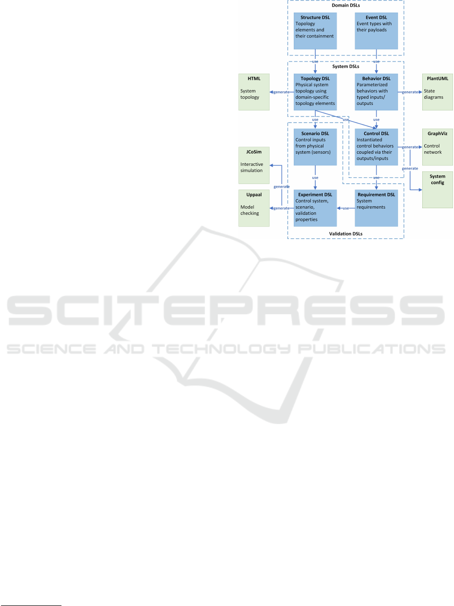
3 DOMAIN MODEL
We have developed a domain model consisting of
eight DSLs to describe IoT applications and their
environment. The languages and their usage rela-
tions are shown in Figure 1; this figure also shows
the model-to-text transformations from the domain
model’s DSLs. We have used Xtext
1
and Xtend
2
for the development of the DSLs and transformations
shown in Figure 1.
Figure 1 distinguishes three categories of lan-
guages: (1) Domain DSLs, (2) System DSLs, and
(3) Validation DSLs. The Domain DSLs allow the
generic domain model to be configured for a spe-
cific application; the Domain DSLs make the domain
model a metamodel for distributed control applica-
tions. The System DSLs use the Domain DSLs to
describe the structure and behavior of an IoT system.
The Validation DSLs allow the validation of a speci-
fied system in its environment.
To explain the DSLs, we use a running example
from the lighting domain. It involves a building with
three rooms: two offices and a central lobby. Each
room has one occupancy sensor and one light point.
The intended behavior in the offices can be speci-
fied in two rules: (1) When an office’s occupancy sen-
sor detects human presence and its light is off, then
the office’s light should switch on. (2) If the light in
an office is on and no office occupancy is detected for
a period of five minutes, then the office’s light should
switch off.
The behavior in the lobby is different: (1) If its
light is off and occupancy is detected in an office or
the lobby, then its light should switch on. (2) If the
lobby’s light is on and no occupancy is detected any-
where for a period of five minutes, then the lobby’s
light should switch off.
1
http://www.eclipse.org/Xtext/
2
http://www.eclipse.org/xtend/
Figure 1: DSLs and model transformations.
3.1 Domain DSLs
As distributed control systems can be very extensive,
it is beneficial to describe their structure hierarchi-
cally. Structure DSL allows the definition of such a
(logical or physical) hierarchy. Instances of Structure
DSL describe the types of structures in a distributed
control system and the hierarchical containment of
these structures.
For the reference example, we can use the logi-
cal structure of a building to describe a light control
system. For this, we distinguish two types of struc-
tures: buildings and rooms. Rooms are assumed to be
contained in buildings.
Event DSL describes the events that are commu-
nicated in the system. This includes the events that
are sent from sensors and to actuators. Each event has
a name and optional arguments.
For our running example, two types of events are
distinguished: occupancy events are used to commu-
nicate occupancy and light level events are used to
communicate a desired light level. Occupancy events
do not have arguments; light level events have one, a
light level represented by an integer value between 0
and 100 percent.
3.2 System DSLs
Topology DSL describes the (logical or physical)
structure of a system in terms of the structure types
defined in a Structure model. The class diagram of
Virtual Prototyping of Large-scale IoT Control Systems using Domain-specific Languages
231
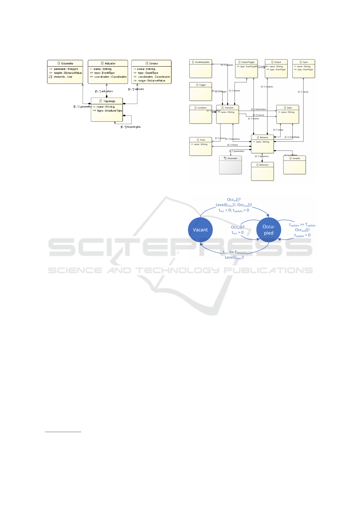
Figure 2: Topology DSL class diagram.
Topology DSL is shown in Figure 2. Topologies are
built up hierarchically; each element of a topology has
sensors and actuators, a physical geometry (used for
visualization), and optional subordinate topologies.
Visualization is supported by a model transforma-
tion: for documentation purposes, Topology models
can be translated into HTML pages with an SVG vi-
sualization of a system’s hierarchical structure.
The running example’s topology consists of four
topological elements: a building and three rooms.
The rooms are subordinate topologies of the building.
The specification of topology models for buildings
need not be done manually; if information is stored in
a Building Information Model (BIM) (Eastman et al.,
2011), then a Topology model can be extracted from
a BIM model automatically.
The desired behavior of an IoT system is realized
by controllers that respond to sensory inputs. An IoT
system may consist of thousands of controllers, but
these typically have similar behaviors. This is ex-
ploited by Behavior DSL, which describes param-
eterized behaviors that can be instantiated for many
different controllers. Behavior DSL is based on the
Sense-Think-Act paradigm. The main classes of Be-
havior DSL are shown in Figure 3. System behaviors
are described in terms of timed state machines. Tran-
sitions between states are triggered by input events or
by timers and may be guarded by conditions. A tran-
sition involves issuing output events, updating local
variables, and resetting timers.
A transformation to PlantUML
3
is used to visual-
ize behaviors; this transformation generates a graphi-
cal representation of the specified timed state machine
from a (textual) Behavior model.
For the running example, we have specified the
timed state machine shown in Figure 4. It involves
two states and four transitions, two of which are self-
transitions. The Vacant state is the behavior’s ini-
tial state; this is the state in which the lights are off.
When an occupancy event is received, a transition to
3
http://www.plantuml.com/
Figure 3: Behavior DSL class diagram.
Figure 4: Behavior model.
the Occupied state is made. The transition also in-
volves switching on the lights by issuing a light level
event with argument L
Occ
. In addition, two timers are
started, an occupancy timer and an update timer. In
the Occupied state, an occupancy event is issued each
time the update timer expires. This allows a controller
to act as an occupancy sensor for other controllers.
For example, the office controllers can provide occu-
pancy input to the lobby controllers. In the Occupied
state, the occupancy timer is reset each time an oc-
cupancy event is received. A timeout of the occu-
pancy timer triggers a transition back to the Vacant
state; this includes switching off the lights by issuing
a light level event with argument L
Vac
.
Variation of a specific behavior is possible using a
behavior’s parameters, which can be set for each dif-
ferent instance. This is done in Control DSL, which
instantiates behaviors for a given system. These in-
stantiated behavior instances are called controllers.
Control DSL also describes the mapping of behavior
onto a system’s topology. This is done by defining
connections between sensors, controllers, and actua-
tors. Sensors can be connected to controller inputs,
MODELSWARD 2019 - 7th International Conference on Model-Driven Engineering and Software Development
232
Figure 5: Control DSL class diagram.
actuators to controller outputs, and controller outputs
to controller inputs. To allow analysis of the influence
of network behavior, edges can be attributed with
probability distributions for message loss and mes-
sage latency. The class diagram of Control DSL is
shown in Figure 5. To visualize the system structure,
we have implemented a model transformation from
Control DSL to GraphViz.
4
We have also implemented code generators for
lighting systems; these are model-to-text transforma-
tions from Control DSL. These transformations are
less generic than the other transformations shown in
Figure 1. This is because the specifics of the underly-
ing technology are part of the model transformation.
The generation of system configurations is outside the
scope of this paper.
In our running example, we distinguish three con-
trollers, one for each room. These controllers imple-
ment the behavior shown in Figure 4. The coupling of
the sensors, controllers, and actuators of our reference
example is shown in Figure 6. It shows the inputs
and outputs of the room controllers. A room’s sensor
is connected to the room controller’s occupancy in-
put and the room controller’s light level output to the
room’s actuator. In addition, the occupancy outputs of
the office controllers are connected to the occupancy
input of the lobby controller. This allows the lobby to
respond to occupancy in the offices. In other words,
the office controllers act as occupancy sensors of the
lobby controller. The same can also be achieved by
directly coupling the office sensors to the lobby con-
troller, but this would involve many connections for
large systems.
4
http://www.graphviz.org/
Figure 6: Control network.
3.3 Validation DSLs
Scenario DSL provides a way to describe the behav-
ior of the environment of a system; it describes sen-
sor events at given moments in time. As each sensor
event needs to be specified explicitly, Scenario DSL
is suited for the specification of simple scenarios, e.g.
test case scenarios. More complex scenarios can be
specified using usage profiles, which should be cali-
brated using data from existing buildings. The pro-
files can be used to generate Scenario models or exe-
cutable models that generate sensor triggers.
For our reference example, we do not include a
Scenario model, because we validate the system using
interactive simulation and exhaustive analysis using
model checking.
Behavior DSL describes an IoT system’s behavior
in a procedural manner using states and transitions. In
other words, it describes how the system should act.
As specifying timed state machines is challenging, es-
pecially for large-scale systems and complex behav-
iors, we use Requirement DSL that describes what
the system should do, i.e. in a declarative manner. For
instance, Requirement DSL can specify what a sys-
tem’s response to a specific user scenario specified
using Scenario DSL should be. It can, however, be
used in a much wider setting. The separation of what
and how also makes communication between techni-
cal and non-technical stakeholders easier, as accep-
tance requirements are not mixed up with technical
details.
The main classes of Requirement DSL are shown
in Figure 7. The language describes requirements in
terms of propositions. Two types of propositions are
distinguished: (1) event propositions hold for an in-
finitesimal time and (2) state propositions hold for
longer time periods. Basic propositions can be com-
Virtual Prototyping of Large-scale IoT Control Systems using Domain-specific Languages
233
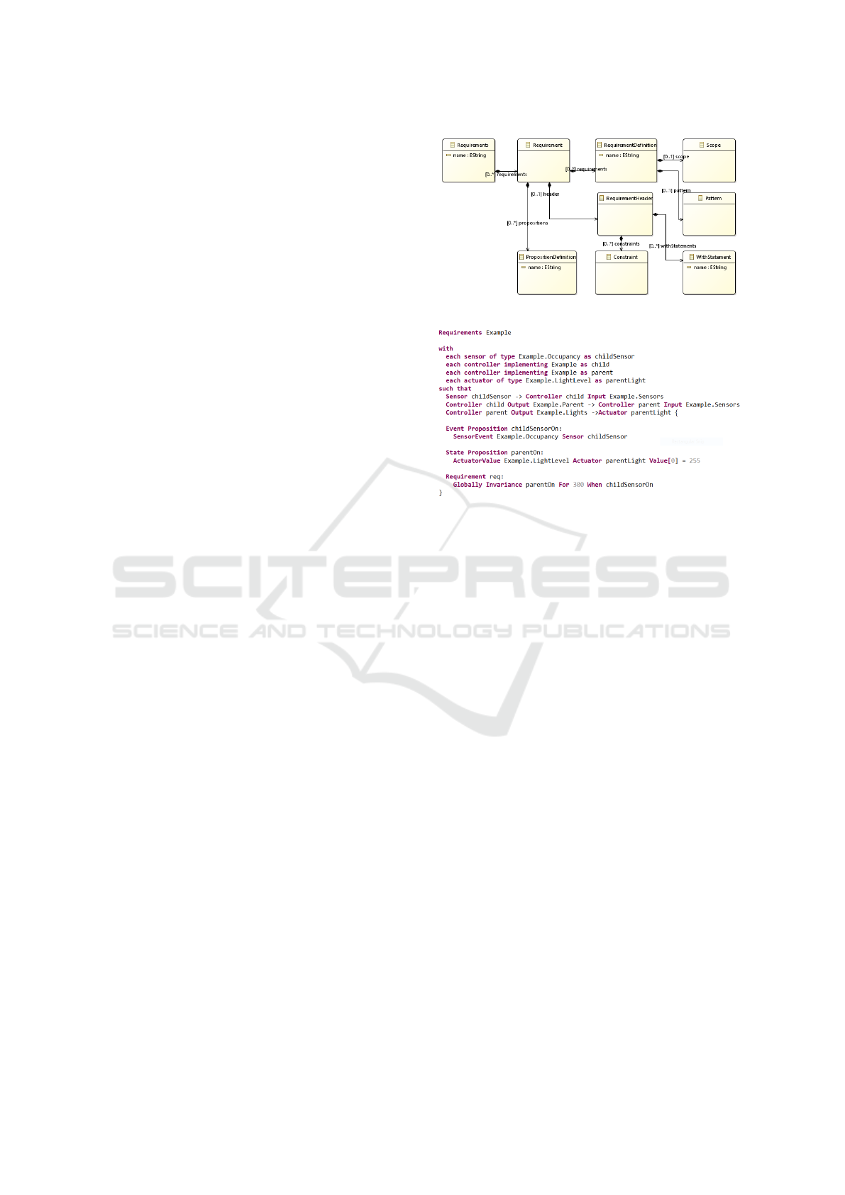
bined in composite propositions, e.g. using Boolean
operators and, or, and not. The circumstances under
which these propositions should hold are described by
a requirement’s scope and pattern. Requirement DSL
allows five scopes (Globally, After, Before, After-
Until, Between) and seven patterns (Response, Prece-
dence, Absence, Universality, Existence, Recurrence,
Invariance), making a total of 35 pattern-scope com-
binations. Most patterns and scopes are based on
those of Dwyer et al. (1998) and Konrad and Cheng
(2005).
As IoT systems can become very extensive, it is
very labor-intensive to specify requirements for all
system components. Because such systems typically
have many instances of the same behavior, Require-
ment DSL allows requirements to be specified for
combinations of sensors, controllers, and actuators
that adhere to a set of constraints. These combina-
tions and the corresponding constraints are specified
in a Requirement’s header, which describes a pattern
that is to be matched in a Control model. As such, Re-
quirement DSL allows a highly efficient specification
of system requirements: a requirement that should
hold throughout an entire system needs to be speci-
fied only once.
For our reference example, we want to specify that
when any office sensor detects occupancy, the lights
in the lobby should switch/be on for at least five min-
utes. This requirement is shown in Figure 8. The
requirement starts with a header specifying the sen-
sors, controllers, and actuators that are to be con-
sidered. This example involves a sensor, two con-
trollers, and an actuator; the sensor is connected to the
first controller, the first controller to the second, and
the second controller to the actuator. There are two
such combinations: (1) Office1’s sensor, Office1’s
controller, the Lobby’s controller, and the Lobby’s
light point, and (2) Office2’s sensor, Office2’s con-
troller, the Lobby’s controller, and the Lobby’s light
point. For large-scale systems, there are typically
many combinations that can be addressed using a sin-
gle requirement.
In the requirement’s body, two propositions are
defined: the first proposition is an event proposition,
which defines the occurrence of an occupancy event
from the sensor; the second is a state proposition,
which defines the actuator/light being fully on. The
bottom statement is the actual requirement. This re-
quirement uses the combination of the Globally scope
and the Invariance pattern. This instance of the In-
variance pattern specifies that each time the sensor is-
sues an occupancy trigger, the actuator should be at
100% on for 300 seconds. The Globally scope indi-
cates that this property should be satisfied under all
Figure 7: Requirement DSL class diagram.
Figure 8: Requirement model.
circumstances.
Experiment DSL combines all information spec-
ified in the other DSLs; it combines instances of Con-
trol DSL, Scenario DSL, and Requirement DSL. The
latter two are optional. As it includes the full system
specification, Experiment DSL is the starting point
for the transformation to analysis models. There are
two transformations from Experiment DSL, one to a
Java co-simulation framework and one to the model
checker Uppaal (Larsen et al., 1995). These are ex-
plained in Section 4.
For the running example, an Experiment model
is the combination of a Control and a Requirement
model. It does not include a Scenario model.
4 SYSTEM VALIDATION
With our domain model, we support two types of sys-
tem validation. Static system validation is discussed
in Section 4.1. As not all system properties can be
validated statically, we also support validation using
executable models. Simulation is explained in Sec-
tion 4.2, model checking in Section 4.3, and their
combination in Section 4.4.
4.1 Static Validation
Correctly specifying a large-scale IoT system is a
huge challenge, as many concepts and settings have
MODELSWARD 2019 - 7th International Conference on Model-Driven Engineering and Software Development
234
to be specified and it is difficult to keep overview. Be-
cause there are typically many similar structures and
behaviors, people easily make specification errors,
e.g. copy-paste errors. Our domain model provides
support for avoiding errors and keeping overview,
while the system is being specified.
For the DSLs introduced in Section 3, specific val-
idation rules have been defined. Naming rules ensure
uniqueness of model element names. This is relevant
for nearly all languages, as the concepts introduced
are used several times. For instance, event types are
used by nearly all other DSLs.
Structure rules validate the structure of DSL in-
stances. For a Behavior model’s state machine, the
reachability and leavability of all states is checked.
For Topology models, it is checked whether the phys-
ical containment matches the logical containment.
Control models are checked for cyclic dependencies
between sensors, controllers, and actuators.
Usage rules validate usage and redundancy of de-
fined concepts. For instance, it is checked whether the
sensors and actuators in a Topology model and all in-
puts and outputs of a Control model are used. More-
over, it is checked whether actuators are connected
to more than one controller, as this may cause non-
deterministic behavior.
Type rules check type consistency. For instance, it
is checked whether sources and destinations of edges
in a controller network have the same event type.
Moreover, it is checked whether controller parameters
and event arguments are within the specified ranges.
4.2 Simulation
Simulation is used to validate the behavior and per-
formance of IoT control systems. These systems
may have thousands of sensors and actuators. To
be able to run a simulation of an IoT system, one
needs a platform that allows the simulation of many
simultaneously executing and communicating simu-
lators. To accomplish this, we have developed a
lightweight Java co-simulation framework (JCoSim)
providing timing and publish-subscribe services, sim-
ilar to HLA’s RTI (Dahman, 1997). We decided to
develop our own services as the open-source versions
of HLA did not offer the desired functionality at that
time and the cost of the commercial versions were
considered too high.
The transformation from Experiment DSL to
JCoSim generates simulators from the components of
the specified IoT system. This involves separate sim-
ulators for sensors, controllers, and actuators. More-
over, edge simulators are generated to handle the
communication in the control network; there is one
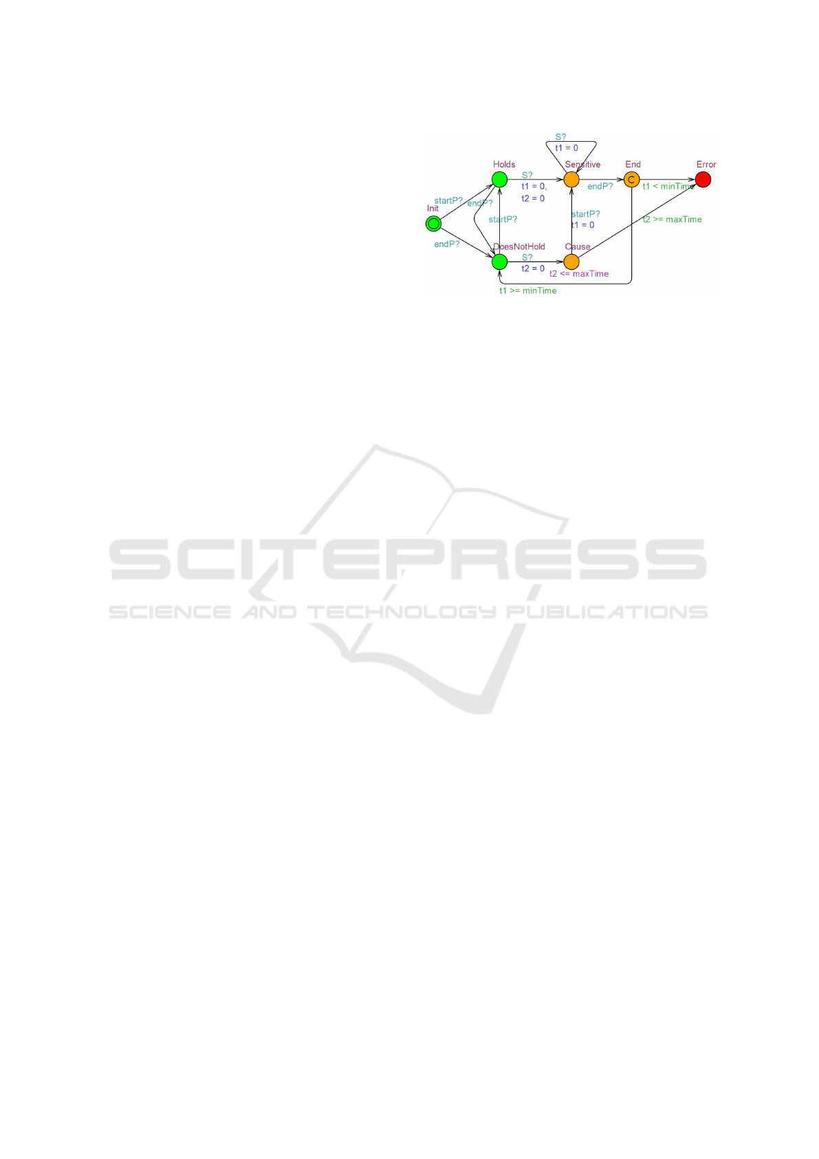
Figure 9: Timed automaton for Globally scope and Invari-
ance pattern.
simulator for each edge in a Control model. The Sce-
nario model specifies the moments at which sensors
trigger. This requires a scenario player simulator that
triggers each sensor simulator to fire a sensor event at
the right time.
Besides simulators for sensors, controllers, and
actuators, the JCoSim model contains monitoring
simulators, which are derived from a Requirement
model. For the propositions and requirements speci-
fied in a Requirement model, proposition and require-
ment monitors are generated. Requirement DSL dis-
tinguishes basic and composite propositions; monitor-
ing simulators are generated for both types. The mon-
itoring simulators for the basic propositions monitor
the controller simulators that are specified in a Con-
trol model; those for composite propositions observe
other proposition simulators.
For each of the 35 pattern-scope combinations of
Requirement DSL, a separate automaton has been de-
fined and these are transformed into simulators in
JCoSim. Figure 9 shows the automaton for the Glob-
ally scope and the Invariance pattern; the automata for
the other scope-pattern combinations were defined by
Buit (2017). The requirement simulators distinguish
normal and forbidden state; the forbidden states rep-
resent requirement violations. During simulation, it is
checked whether they enter a forbidden state. If they
do, e.g. the Error state in the automaton in Figure 9,
then the user is notified of the requirement violation.
For our running example, the transformation from
Experiment DSL to JCoSim results in a model with
23 simulators: 3 sensor simulators, 3 controller sim-
ulators, 3 actuator simulators, 8 edge simulators, 4
proposition simulators, and 2 requirement simulators.
4.3 Model Checking
Co-simulation provides a scalable system analysis
method; it allows thousands of components to be sim-
ulated simultaneously. A drawback of simulation is
the fact that it is limited to a single scenario, typically
Virtual Prototyping of Large-scale IoT Control Systems using Domain-specific Languages
235

a good-weather scenario. As IoT systems may be very
large and may have a lifespan of several decades, the
analysis of good-weather behavior is not sufficient to
find all errors that appear in a system’s lifetime. We
use model checking to analyze a system’s behavior
under all possible input scenarios. This has been re-
alized by a transformation from Experiment DSL in-
stances to Uppaal models (Larsen et al., 1995).
With respect to the generated automata, the trans-
formation is very similar to the transformation to
JCoSim. The only difference is that the generated Up-
paal models do not have actuator automata; actuators
are modeled using global variables. So whereas the
JCoSim model for the reference example involves 23
simulators, the corresponding Uppaal model has only
20 automata.
There are some conceptual differences between
the timed state machines specified in Behavior DSL
and Uppaal’s timed automata. The main differences
are: (1) Uppaal does not allow multiple synchroniza-
tions per transition and (2) Uppaal does not allow
synchronizations with data. The former has been ad-
dressed by introducing sequences of synchronizations
between committed states; these committed states
make sequences of transitions atomic. We addressed
the latter by communication using global variables.
The Uppaal model contains the same proposition
and requirement automata as the JCoSim simulation
model. JCoSim is restricted to monitoring whether
forbidden states are entered. Besides entering of for-
bidden states, the Uppaal models allows other types
of analysis. An overview of the properties that can be
checked is given by Buit (2017).
For our running example, an Uppaal model with
20 automata and 2 queries is generated, one query per
requirement automaton. Uppaal’s exhaustive analysis
shows that both queries are satisfied: i.e. when a sen-
sor in an office detects occupancy, then the lights in
the lobby are/switch on for at least five minutes.
4.4 Simulation and Model Checking
Model checking provides an exhaustive system anal-
ysis; this means that it finds requirement violations
even under very unlikely circumstances. Unfortu-
nately, model checking is not sufficiently scalable to
analyze the (possibly) huge state space of an IoT sys-
tem. This does not mean that model checking does
not provide value for the analysis of complex systems.
To manage complexity, our approach breaks down
the system into manageable subsystems using the the
Control model as a basis. Instead of analyzing all con-
trollers and all requirements simultaneously, one can,
similar to the approach of Doornbos et al. (2015), it-
eratively analyze all combinations of one controller
and one requirement. The state space of these combi-
nations is typically small enough to allow exhaustive
analysis.
A second way in which model checking adds
value is by combining the strengths of simulation and
model checking. Simulation is sufficiently scalable
to simulate large-scale systems, but large-scale sim-
ulations provide limited diagnostic capabilities. If
simulation detects a requirement violation in a sys-
tem, then model checking can be used for diagnosis.
Model checking should zoom in on the controllers
causing the violation. As a requirement violation is
known to exist, model checking’s exhaustive analy-
sis will find it and provide a minimal trace leading to
the violation. This trace is translated into a Scenario
model that can be used to identify the underlying root
cause.
5 CASE STUDY
The domain model introduced in Section 3 has been
applied for intelligent lighting systems. Such systems
typically consist of devices connected via an IP com-
munication network. These devices need not be re-
stricted to the lighting domain as lighting systems are
more and more integrated with other building man-
agement systems, such as HVAC, blinds, and eleva-
tors. The input devices include a variety of sensors
(e.g. occupancy and light level sensors), buttons for
scene selection or dimming, but also mobile devices
for personalized control. A lighting system’s output
devices are light points, units consisting of one or
more LED units with all necessary parts and wiring.
An existing building has been used as the basis
for a case study of our domain model: Witte Dame
5
is a renovated factory in the center of Eindhoven. In
the context of the OpenAIS project,
6
the traditional
lighting system on the building’s fifth floor has been
replaced by a new intelligent lighting system. This
system was modeled and simulated using our domain
model. The light system covers 367 light points with
over 1,300 behavioral functions. The floor plan is
shown in Figure 10.
The first step in the case study involved the val-
idation of the intended Behaviors. This was done
by deploying a Behavior on a relevant part of Witte
Dame and validating whether the deployed Behavior
was as expected. For this, we used the simulation and
model checking as explained in Section 4. To allow
5
http://www.dewittedame.nl/
6
http://www.openais.eu/
MODELSWARD 2019 - 7th International Conference on Model-Driven Engineering and Software Development
236
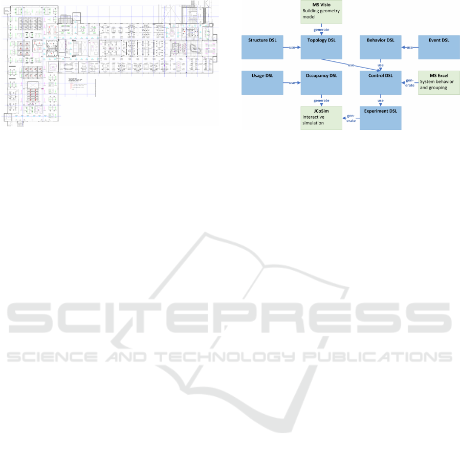
Figure 10: Floor plan of Witte Dame’s fifth floor.
discussion with stakeholders, we developed visualiza-
tion tooling that allows interactive simulation. A user
can trigger sensors in the interactive visualize and ob-
serve the resulting system behavior.
The combination of Requirement DSL and the
interactive visualization has shown its great value.
While simulating a lighting system, the status of the
sensors and light points is visualized. For instance,
the status of sensors and buttons is shown and the light
level of light points. In addition, the status of the re-
quirements is shown using a transparent overlay over
the corresponding devices. A requirement’s overlay
starts green and turns red when the requirement is vi-
olated.
The second step involved the validation of the sys-
tem. Manually creating DSL instances for hundreds
of light points would be a lot of effort and would be
extremely error prone. Hence we developed a pipeline
of model transformations (Rieger et al., 2018). Dedi-
cated tooling has been developed to generate Control
models. The corresponding work flow is visualized in
Figure 11. There are two inputs: (1) a Microsoft Visio
file describing the geometry of the floor plan includ-
ing the location of the sensors and light points, and
(2) a Microsoft Excel document describing the system
behavior and their deployment onto the devices in the
system. From this and manually created Structure,
Event, and Behavior models, two models are gener-
ated: (1) a Topology model and (2) a Control model.
From these generated models, Java simulation models
are generated as explained in Section 4.2.
To thoroughly test a lighting system using simu-
lation, elaborate scenarios need to be specified. Be-
cause Scenario DSL is not suited to manually spec-
ify long scenarios and manually triggering a gener-
ated lighting system is both tedious and inefficient,
we have developed Usage DSL and Occupancy DSL
specifically for human behavior in buildings. These
languages allow people’s activities and their mapping
onto locations in a building to be specified. The sim-
ulation of people’s movement and activities in the
Figure 11: Generation of co-simulation models.
building generate sensor triggers that automatically
trigger the generated lighting simulation.
A screenshot of the interactive simulation is
shown in Figure 12. It shows Witte Dame’s floor plan
and the status of the light points in the system. Apart
from lighting behavior, the simulation also considers
the system’s performance with respect to energy us-
age, an important KPI for lighting systems (Baum-
gartner et al., 2012). The virtual prototype allows an
assessment of the energy usage for different behaviors
and behavior settings. For instance, one can analyze
the influence of occupancy timeout periods on a light-
ing system’s energy usage.
The co-simulation has proven to be very useful in
the design of the large-scale virtual prototype. Dur-
ing the verification of the control behavior of Witte
Dame more than ten errors have been identified and
corrected. These included (1) incorrect or missing
control group allocations of light points, (2) incorrect
sensor linking, and (3) missing or incorrect linking
of controllers. Although these errors could have been
found by manual inspection, co-simulation greatly ac-
celerated the errors’ detection and correction.
Furthermore, the validation of the behavior with
lighting experts has led to renewed discussions on
customer-desired behavior leading to several adapta-
tions to the initial control design for the Witte Dame
prototype including improved controller linking and
better behavior specification. These results clearly il-
lustrate the power of the co-simulation environment.
6 CONCLUSION
In this paper, we have presented a domain model for
distributed control systems, which comprises eight
DSLs that each capture one system aspect. For
instance, it includes two languages that allow the
generic domain model to be adapted for a certain do-
main. Moreover, the system’s structure is separated
from its behavior, allowing reuse of behavior in mul-
Virtual Prototyping of Large-scale IoT Control Systems using Domain-specific Languages
237
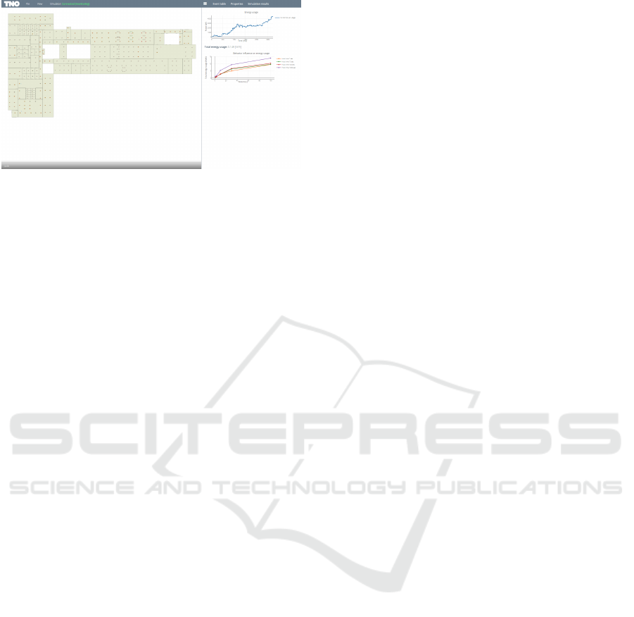
Figure 12: Simulation of Witte Dame case study.
tiple locations.
The domain model is the basis for a virtual pro-
totyping application, which supports both simulation
and model checking. For both kinds of analysis, we
have separated what the system should do from how
it does this. This provides powerful analysis support
for large-scale distributed control systems: Require-
ment DSL is the basis for the generation of monitor-
ing automata that are included in the generated sim-
ulation and model checking models. These automata
observe the system and notify the user of requirement
violations. The combination of simulation and model
checking is of especially great value: (1) simulation
allows large systems and many requirements to be
analyzed simultaneously, and (2) model checking al-
lows diagnosis of an identified requirement violation
by zooming in on the violating subsystem.
Our co-simulation framework allows scalable
simulation of thousands of sensors, controllers, and
actuators. In the lighting domain, we have shown that
the combination of our generic co-simulation with
domain-specific front-ends and back-ends is very
valuable: (1) usage and occupancy front-ends were
used to generate realistic building occupancy patterns,
and (2) a visualization back-end was used to visualize
system behavior and allow users to interact with a run-
ning simulation. The interactive visualization allows
early feedback of system behavior, possibly already
during a system’s sales phase.
7 FUTURE WORK
The domain model described in Section 3 is focused
on the interaction between distributed sensors, con-
trollers, and actuators. Implicitly, it is assumed that
this interaction does not involve complex data being
shared. For some distributed control systems, data
plays a prominent role. For instance, in the logistic
domain, one needs to keep track of orders and re-
sources. To include such concepts, our domain model
needs to be extended by a Data DSL, which is used
to define data structures, which can be used by the
other DSLs. This would allow analysis of logistic
control systems such as the ones studied by Verriet
et al. (2012).
The system validation described in Section 4 pro-
poses simulation and model checking to detect and
correct system errors. Not all errors can be addressed
using these techniques: e.g. configuration errors can
be found, but hardware failures cannot. To allow more
types of errors to be found, a root cause analysis ap-
proach is proposed. This approach feeds our virtual
prototype with actual sensor data and compares the
response of the virtual prototype’s actuators to the ac-
tual actuator responses. In case of differences, a rea-
soning framework is to be used to identify the most
probable root cause.
The domain model described in this paper al-
lows the specification of distributed control systems.
The desired system behavior can be realized in many
ways. For instance, one may decide to have redundant
controllers to improve system reliability. The neces-
sary communication of the redundant controllers can
be specified in terms of Behavior models. This mixes
functional and non-functional system aspects. A chal-
lenging open issue is the separation of these aspects.
Specifically, we would like to specify system behav-
ior in a deployment-agnostic manner and describe de-
ployment, and the corresponding communication, in
a separate Deployment DSL. This would allow ef-
ficient analysis of different deployment strategies, as
the behavior needs to be specified only once.
ACKNOWLEDGEMENTS
The research is carried out as part of the Prisma pro-
gram and H2020 OpenAIS project under the respon-
sibility of Embedded Systems Innovation (ESI) with
Philips Lighting as the carrying industrial partner.
The Prisma program is supported by the Netherlands
Ministry of Economic Affairs, the OpenAIS project
is co-funded by the Horizon 2020 Framework Pro-
gramme of the European Union under grant agree-
ment number 644332 and the Netherlands Organisa-
tion for Applied Scientific Research TNO.
REFERENCES
Baumgartner, T., Wunderlich, F., Jaunich, A., Sato, T.,
Bundy, G., Grießmann, N., and Hanebrink, J. (2012).
Lighting the way: Perspectives on the global lighting
market. Technical report, McKinsey & Company, Inc.
MODELSWARD 2019 - 7th International Conference on Model-Driven Engineering and Software Development
238

Beckers, J. M. J., Muller, G. J., Heemels, W. P. M. H.,
and Bukkems, B. H. M. (2007). Effective indus-
trial modeling for high-tech systems: The example of
happy flow. In 17th INCOSE International Sympo-
sium, pages 1758–1769, San Diego, CA. INCOSE.
Bertran, B., Bruneau, J., Cassou, D., Loriant, N., Balland,
E., and Consel, C. (2014). Diasuite: A tool suite to de-
velop sense/compute/control applications. Sci. Com-
put. Program., 79:39–51.
Broy, M., Kirstan, S., Krcmar, H., Sch
¨
atz, B., and Zimmer-
mann, J. (2012). What is the benefit of a model-based
design of embedded software systems in the car indus-
try? In Emerging Technologies for the Evolution and
Maintenance of Software Models, pages 343–369. IGI
Global, Hershey, PA.
Buit, L. J. (2017). Developing an easy-to-use query lan-
guage for verification of lighting systems. Master’s
thesis, University of Twente, Enschede.
Dahman, J. S. (1997). High level architecture for simula-
tion. In 1st International Workshop on Distributed
Interactive Simulation and Real Time Applications,
pages 9–14, Eilat. IEEE.
D’Angelo, G., Ferretti, S., and Ghini, V. (2017). Multi-level
simulation of internet of things on smart territories.
Simul. Model. Pract. Theory, 73:3–21.
Doornbos, R., Verriet, J., and Verberkt, M. (2015). Ro-
bustness analysis for indoor lighting systems: An ap-
plication of model checking in large-scale distributed
control systems. In 10th International Conference on
Systems, pages 46–51, Barcelona. IARIA.
Dwyer, M. B., Avrunin, G. S., and Corbett, J. C. (1998).
Property specification patterns for finite-state verifica-
tion. In 2nd Workshop on Formal Methods in Software
Practice, pages 7–15, Clearwater Beach, FL. ACM.
Eastman, C., Teicholz, P., Sacks, R., and Liston, K. (2011).
BIM Handbook: A Guide to Building Information
Modeling for Owners, Managers, Designers, Engi-
neers and Contractors. Wiley, Hoboken, NJ.
France, R. and Rumpe, B. (2007). Model-driven develop-
ment of complex software: A research roadmap. In
2007 Workshop on the Future of Software Engineer-
ing, pages 37–54, Minneapolis, MN. IEEE.
Gruhn, V. and Laue, R. (2006). Patterns for timed property
specifications. Electron. Notes Theor. Comput. Sci.,
153:117–133.
Haskins, B., Stecklein, J., Dick, B., Moroney, G., Lovell,
R., and Dabney, J. B. (2004). Error cost escalation
through the project life cycle. In 14th INCOSE In-
ternational Symposium, pages 1723–1737, Toulouse.
INCOSE.
Hendriks, M., Geilen, M., Behrouzian, A. R. B., Basten,
T., Alizadeh, H., and Goswami, D. (2016). Checking
metric temporal logic with trace. In 16th International
Conference on Application of Concurrency to System
Design, pages 19–24, Torun. IEEE.
Hooman, J. (2016). Industrial application of formal models
generated from domain specific languages. In The-
ory and Practice of Formal Methods, volume 9660 of
Lecture Notes in Computer Science, pages 277–293.
Springer, Berlin.
Konrad, S. and Cheng, B. H. (2005). Real-time specifi-
cation patterns. In 27th International Conference on
Software Engineering, pages 372–381, St. Louis, MO.
ACM.
Koymans, R. (1990). Specifying real-time properties with
metric temporal logic. Real-Time Syst., 2:255–299.
Kurtev, I., Hooman, J., and Schuts, M. (2017). Run-
time monitoring based on interface specifications. In
ModelEd, TestEd, TrustEd, volume 10050 of Lecture
Notes in Computer Science, pages 335–356. Springer,
Berlin.
Larsen, K. G., Pettersson, P., and Yi, W. (1995). Model-
checking for real-time systems. In International Sym-
posium on Fundamentals of Computation Theory, vol-
ume 965 of Lecture Notes in Computer Science, page
62–88. Springer, Berlin.
Melleg
˚
ard, N., Ferwerda, A., Lind, K., Heldal, R., and
Chaudron, M. R. V. (2016). Impact of introducing
domain-specific modelling in software maintenance:
An industrial case study. IEEE Trans. Softw. Eng.,
42:245–260.
Meyers, B., Wimmer, M., van Vangheluwe, H., and De-
nil, J. (2013). Towards domain-specific property lan-
guages: The promobox approach. In 2013 Work-
shop on Domain-specific Modeling, pages 39–44, In-
dianapolis, IN. ACM.
Rieger, C., Westerkamp, M., and Kuchen, H. (2018).
Challenges and opportunities of modularizing textual
domain-specific languages. In 6th International Con-
ference on Model-Driven Engineering and Software
Development, pages 387–395, Funchal. SciTePress.
Serral, E., Valderas, P., and Pelechano, V. (2010). Towards
the model driven development of context-aware per-
vasive systems. Pervasive Mob. Comput., 6:254–280.
Theelen, B. and Hooman, J. (2015). Uniting academic
achievements on performance analysis with industrial
needs. In Quantitative Evaluation of Systems, volume
9259 of Lecture Notes in Computer Science, pages 3–
18. Springer, Berlin.
Verriet, J., Liang, H. L., Hamberg, R., and van Wijngaar-
den, B. (2012). Model-driven development of logistic
systems using domain-specific tooling. In Complex
Systems Design & Management 2012, pages 165–176,
Paris. Springer.
V
¨
olter, M. (2010). Architecture as language. IEEE Softw.,
27:56–64.
Virtual Prototyping of Large-scale IoT Control Systems using Domain-specific Languages
239
