
Hull Resistance Analysis of Hydrofoil Mode-crocodile Ship Prototype
Wisnu Wardhana
1,a
, Meitha Soetardjo
2
, Ede M. Wardhana
3
, Sujantoko
1
1
Department of Ocean Engineering, Institut Teknologi Sepuluh Nopember, Indonesia
2
PT Tunas Maritim Global, Indonesia
3
Department of Marine Engineering, Institut Teknologi Sepuluh Nopember, Indonesia
Keywords: CFD Resistance Simulation, Crocodile Ship Prototype, RANSE Methods.
Abstract: This study presents resistance simulation of hydrofoil mode crocodile ship prototype in calm seawater
conditions using CFD in hydrofoil mode. The RANSE (Reynolds Averaged Navier-Stokes Equation) methods
are used for the viscosity solution of turbulent flow around the ship’s hull. Different turbulent models are used
for comparing the results in ship resistance calculations, in order to select the most appropriate methods. This
study on the creation of geometrical model considered exact pressure and velocity around hydrofoil mode
vessel submerged in calm seawater conditions, grid generation, setting mathematical model in Fluent and
evaluation of the simulations results. Comparison with experimental results also carried out.
1 INTRODUCTION
The prototype of Crocodile Ship has been designed
and fabricated to combine operational modes of
hydrofoil vessels, surface ships and submarines in its
mission. The vessel is designed with front and rear
wings of hydrofoil that can be controlled in all modes
of ship operation. The current paper investigates the
ship resistance in hydrofoil operation mode using
numerical simulation based on RANS Equations.
Assessment of ship resistance started to gain
importance with the advent of machine-propelled
ships in the early nineteenth century. The dependence
of ship resistance on velocity was necessary for
calculating the required power of the propulsion
system. Computational Fluid Dynamics (CFD) used
in this research, requires cooperation of several
disciplines such as mathematics, physics and
information technology for the development of this
method. CFD simulation gained larger scale
acceptance in the 90's and has sometimes replaced
experiments in many fields today. The CFD
simulations have commonly been integrated into
project of every new vessel, especially in the design
of seagoing ships. The approach for assessing ships
resistance by using experimental and CFD
simulations are also a part of this study. This study
aims at developing the process and selection of
appropriate methods for creating the geometrical
model, setting-up the mathematical model and
creating the preliminary CFD simulation. This will be
applied in crocodile ship prototype in calm seawater,
which represents seawater condition in archipelagic
countries such as Indonesia.
This paper presents a numerical study in different
speed conditions. This study has predicted resistances
characteristics of special hull using numerical
simulation and comparing the results with the
experimental results in the towing tank.
2 METHODOLOGY
This study is intended to conduct calculation as a
technique to predict resistance for ships. This method
starts with full scale dimension of ship model ran in
CFD analysis. The CAD ship model have previously
been conducted at various speed condition in calm
seawater: length (L) of 11m, breadth (B) of 3m, depth
(H) of 2m, maximum draft (T) of 1.8m and maximum
speed of carriage is at 4.0 m/s. Model resistance was
measured with dynamometer. The model was
attached to the measuring head of the resistance
dynamometer by a connector which can transmit and
measure only a horizontal tow force, even though the
model should be at the correct calculated
displacement. The resistance dynamometers were
attached at the LCB of the model as close to the shaft
line as possible. The electrical signal from
dynamometer are transmitted through overhead
136
Wardhana, W., Soetardjo, M., Wardhana, E. and Sujantoko, .
Hull Resistance Analysis of Hydrofoil Mode-crocodile Ship Prototype.
DOI: 10.5220/0010856100003261
In Proceedings of the 4th International Conference on Marine Technology (senta 2019) - Transforming Maritime Technology for Fair and Sustainable Development in the Era of Industrial
Revolution 4.0, pages 136-140
ISBN: 978-989-758-557-9; ISSN: 2795-4579
Copyright
c
2022 by SCITEPRESS – Science and Technology Publications, Lda. All rights reserved
cables on trolley wires to the signal conditioning
equipment and ultimately to the computer. Data were
sampled for resistance and speed in the longitudinal
direction Fx. The forces are measured in mass (kg)
and converted to N through gravity (g) multiplication.
2.1 Experimental Setup
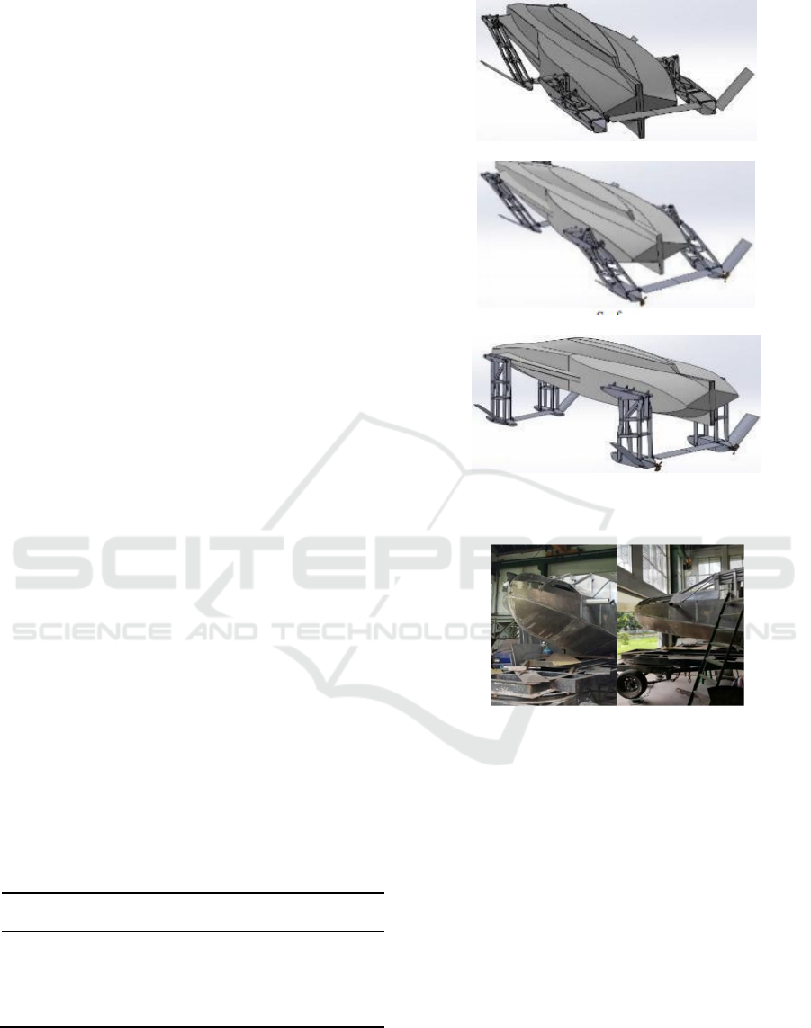
3D model of the crocodile hull was created according
to the dimensions (as shown in Tab.1) and shapes
defined seen in Figure 1 below which showed the
strout and nacelle positions under three modes of
operation. The vessel itself is currently under
construction in Institut Teknologi Sepuluh Nopember
(ITS) Surabaya as shown in Figure 2.
The calculation of the total resistance was
achieved by using the procedure as outlined in the
ITTC recommended procedures (ITTC, 2011). The
total resistance was calculated where the total hull
resistance is a function of hull form, ship speed, and
water properties, the coefficient of total hull
resistance is also a function of hull form, ship speed,
and water properties. The coefficient of total hull
resistance is found from the following equation.
𝑅
0.5. 𝜌. 𝐶𝑡. 𝑆. 𝑉
(1)
The equation for the Froude number is
𝐹𝑟
𝑉
.
𝑔𝐿
(2)
Where:
Ct : total resistance coefficient
RT : total hull resistance
: water density (kg/m
3
)
V : velocity (m/s)
S : wetted surface area of the
underwater hull (m
2
)
L : ship length (m)
g : gravity (m/s
2
)
(a) Submarine
(b) Surface
(c) H
y
drofoils
Figure 1: 3D Model Crocodile hull condition.
Figure 2: Crocodile hull prototype under construction.
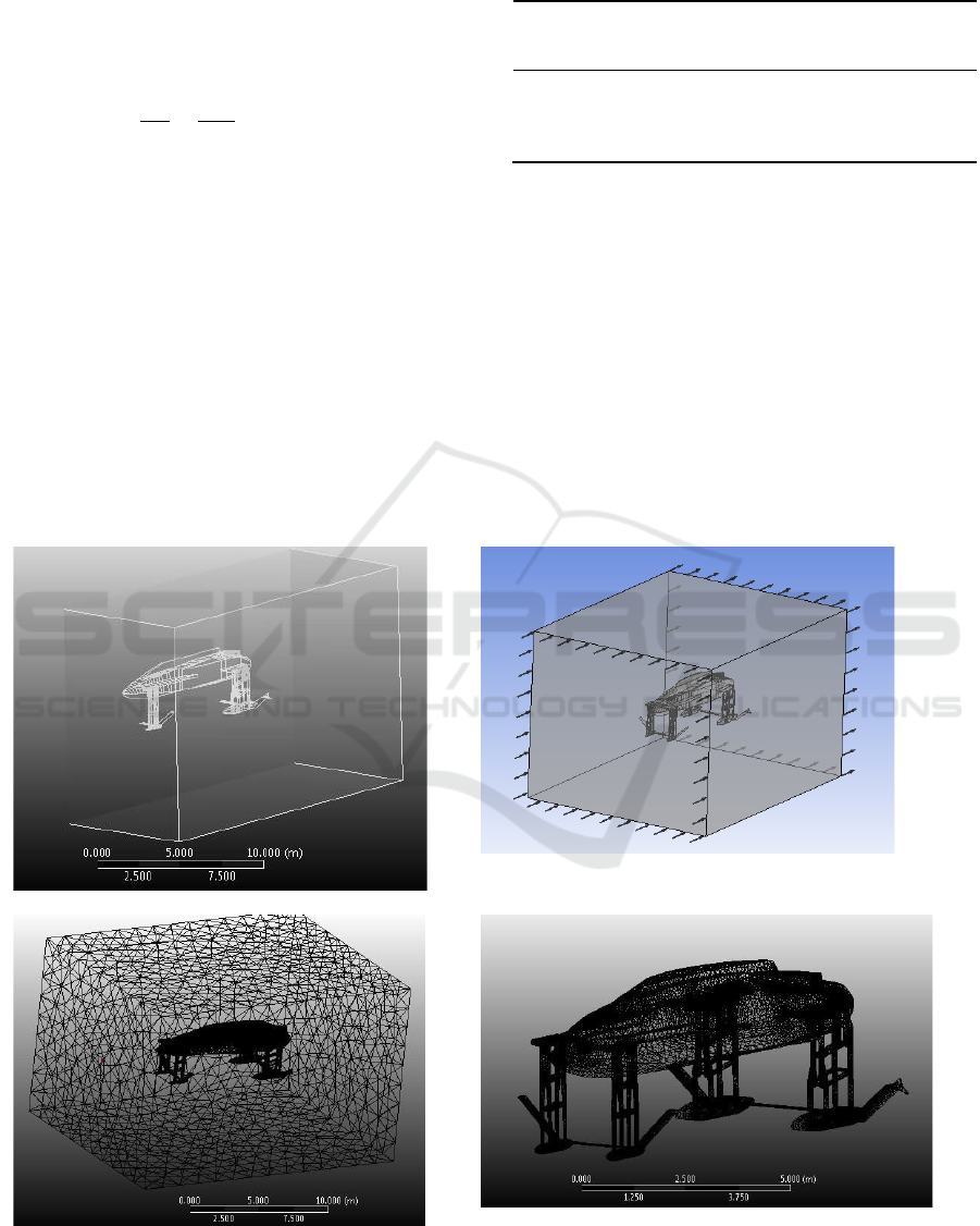
2.2 Numerical Setup
The simulation is made for various speed at 10, 20,
30, and 40 knots velocity of the crocodile prototype.
The Realizable k- epsilon, viscous models were also
used. For a detailed explanation of the discretization
of FVM, please refer to the book published by
Versteeg and Malalasekera (2007). The calculations
involved in this study are all for steady cases. Since
there are two types of flows solved with FVM
(inviscid and viscous), conditions of the viscous
solver is divided into two. For the viscous solver, the
realizable and standard k –ε turbulence model is used.
The inlet of the fluid domain is selected as velocity
inlet and the outlet as pressure outlet. The top and
bottom walls are in symmetrical boundary condition.
Simple algorithm was used for pressure- velocity
coupling, which is widely used and considered the
Table 1: Principal dimension crocodile ship
Principal
Dimension
Full Scale Model Scale
LOA
(
m
)
11 1.1
B (Breadth) (m) 3.0 0.3
T Draft
(
m
)
0.75 0.075
Full/Model
Scale ratio ()
1 1/10
Hull Resistance Analysis of Hydrofoil Mode-crocodile Ship Prototype
137
most suitable method. Pressure, momentum,
turbulent kinetic energy and dissipation rate are all
selected as second order.
This approach is called Reynolds Averaged
Navier Stokes Equation (RANSE):
𝜕𝜌
𝜕𝑡
𝜕
𝜕𝑥
𝜌𝑣
(3)
In this study, the flow is steady and
incompressible and the effects of free surface and
cavitation are ignored. Due to incompressible flow,
energy equation is automatically eliminated from the
conservation equations and only the continuity and
momentum equations are left. The viscosity term in
Equation (3) may also be eliminated depending on the
type of solution FVM will return.
3 RESULT AND DISCUSSION
Results from Numerical Simulation using K-
EPSILON Realizable Model Scale Results are shown
in table below that fr = 0.5, 0.99, 1.49 and 1.98
resistance obtained by results data of Force in x-axis
for each Froude Number are 28.4, 113.01, 253.41,
and 468.12 kN.
Numerical Simulation using K-EPSILON
Realizable Model Scale graph grows exponentially as
Froude Number increased.
(a) View 1 (b) View 2
(c) View 3 (d) View 4
Figure 3: 3D crocodile ship meshed model.
Table 2 : K-epsilon realizable model scale resul tnumerical
simulation.
Froude
Number
F
r
Velocity
model Vs
(
m/s
)
Velocity
model Vs
(
knots
)
Force in
x- axis
(
kN
)
Model Scale
Resistance
(
kN
)
0.55.14 10 28.4 32.5
0.9910.29 20 113.01 122.67
1.4915.43 30 253.41 257.83
1.9820.58 40 468.12 472.17
senta 2019 - The International Conference on Marine Technology (SENTA)
138
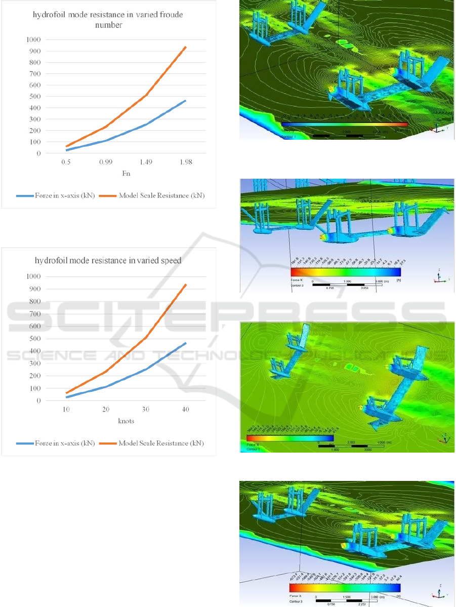
Figure 4: Resistance of each froude number in full scale
CFD experiment.
Figure 5: Resistance in each speed of full scale CFD
experiment.
Figure 6: Force in x-axis contour at 10 knots speed of
Hydrofoil Mode.
Figure 7: Force in x-axis 20 knots speed of Hydrofoil Mode.
Figure 8: Force in x-axis 30 knots speed of Hydrofoil Mode.
Figure 9: Force in x-axis 40 knots speed of Hydrofoil Mode.
Hull Resistance Analysis of Hydrofoil Mode-crocodile Ship Prototype
139
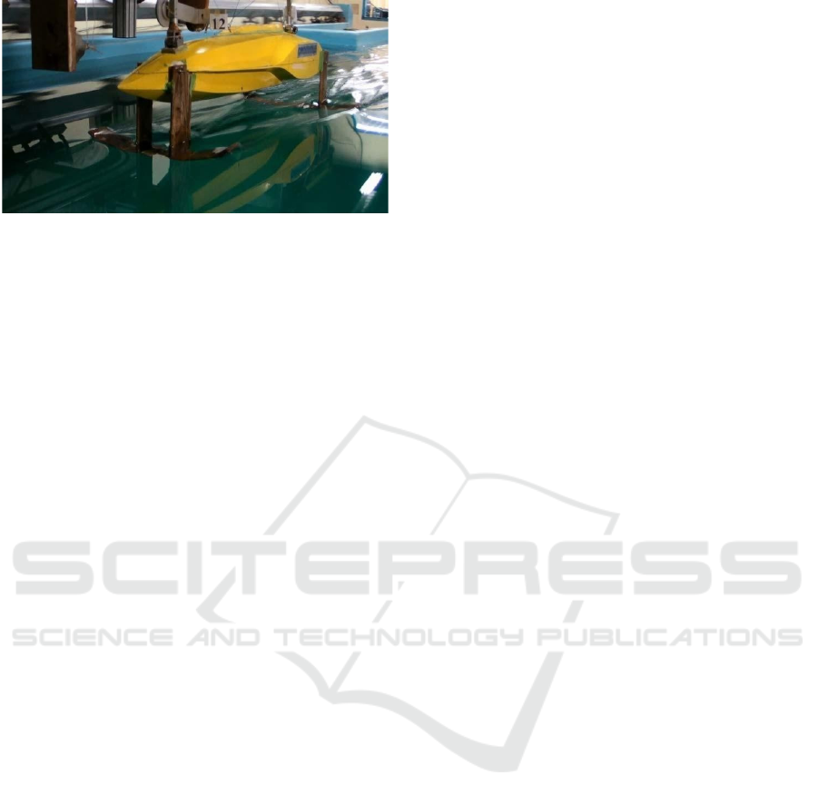
Figure 10: Towing tank test at 12knots speed.
4 CONCLUSION
This paper investigates the resistance and
hydrodynamic crocodile ship in hydrofoil condition.
A finite volume based RANS solver has been used to
evaluate the performance of these systems.
ACKNOWLEDGEMENTS
This work was financially supported by the Ministry
of Research, Technology and Higher Education of
Indonesia.
REFERENCES
Jones, B, 2008. ”Technological Aspects of Submarine”,
Journal of Underwater Tech, Canberra
Lewis,, E.V. 2002. ”Principle of Naval Architecture”,
London
Sarwito, S., 2015. ”Main System Development of
Crocodile- Hydrofoil Craft for Efficient and Effective
Sea Defense and Security”, PUPT Kemenristek-dikti
Walree, van F., 2007. ”Hydrofoils, Model Tests
andComputations”,
Hydrodynamics: Computations, Model Tests and Reality
Wardhana, W., 1998. ”Numerical and Experimental
Assessment of Hydrofoil Wing Interactions”, RUT IV
Wardhana, W., 2004. ”Numerical and Experimental of
Manned Hydrofoil Model”, RUT X
Wardhana, W., 2007. ”Numerical and Experimental
Assessment of Midget for Indonesian Purposes”, Riset
Insentif, Ristek, Jakarta
Wardhana, W., 2008. “Military Submarine Design for
Indonesia’s Defence and Security Purposes”, CCCL-
ITS International Joint Seminar, ITS Surabaya
Wardhana, W., 2013. ”Numerical and Experimental of
Crocodile- Hydrofoil Craft for Future Technology of
Sea Defense and Security”, RUSNAS, Kemendikbud-
Dikti
Wardhana, W., 2013. ”Design Philosophy of Crocodile-
Hydrofoil Craft”, SENTA ITS
Wardhana, W., 2015. ”Design Development of Crocodile-
Hydrofoil Craft for Future Technology of Sea Defense
and Security”, PUPT, Kemenristek-dikti
Versteeg, H., K. and Malalasekera, W., 2007. An
introduction to computational fluid dynamics-the finite
volume method. Glasgow
senta 2019 - The International Conference on Marine Technology (SENTA)
140
