
Effect of Engine Fastening Points’ Amount on the Vessel’s
Foundation towards Vibration Transmissibility Value in Traditional
Vessel Structures
Debby R. Lekatompessy
1,a
1
Department of Naval Architecture, Universitas Pattimura, Kampus Poka, Ambon, Indonesia
Keywords: Engine Foundation, Traditional Ship Structures, Transmissibility, Vibration.
Abstract: In the rubber damper designed in the previous study, vibration was reduced by 65% on engine no. 1 and 59% in
engine no. 2 with a considerable amplitude value of 0.0276 mm and 0.0282 mm, respectively. By using the
Barkan engine's allowable amplitude ranging from 0.02 mm - 0.03 mm, after the installation of a rubber damper,
the vibration can be reduced to safe limit. The research continues by analysing the machine foundation-stretching
system with the amount of fastening points of 2, 3, and 4. The increase in the number of fastening points causes
the amplitude to be reduced even further. The calculation results can be seen by reducing the value of the
transmission force to the foundation. By doing so, the amplitude value decreases as the engine’s load decreases
due to the system's work. The number of fastening points affects the value of the distribution of the bending
stress (s) and shear stress (ss). Increasing the fastening point reduces the value of the bending stress (s) and shear
stress (ss). The allowable bending stress (s) and shear stress (ss) used are 6.4 MPa and 0.45 MPa consecutively,
given by the National Design Specification. The calculation results show the value is below the allowable limit.
Based on the calculation results, the smallest amplitude value is obtained at the four-point fastening points.
Therefore, it is better if the amount of existing fastening points is increased. From these results, it can be seen
that the foundation is still within the safety limits.
1 INTRODUCTION
Ships with outboard engine type, vibrations
transmitted to the foundation beam without damping
exceeded Barkan permissible amplitude, i.e., 0.02
mm to 0.03 mm in the vertical direction (Srinivasulu,
1980). This condition indicates that the system
requires a damper that can reduce vibration to a safe
limit. Calculations must be made using Barkan
permissible amplitude limits. Also, the vibration
limits are permitted for structural damage, machinery
vibration, and human perception in graphical form for
operator safety (Hopcroft and Skinner, 2005).
Damping in this study uses rubber material with E
value at 2.3 x 10⁹ N/m2 . The rubber dimensions are
determined through variations in prices of c and k
with thickness t = 0.2 cm to 3 cm (Lekatompessy et
al., 2013). Based on measurement at Point F around
the beam foundation, an effective damping rubber
dimension is obtained at 8 x 5 x 2 cm.
At this point, the most significant excitation force
(F0) and the smallest excitation frequency () are
obtained, with the most substantial amplitude value
(Lekatompessy, 2003).
In further research, the fishing factor is seen by
analysing the effect of the number of fishing spots on
the distribution of vibrations and loads on the wooden
ship's engine foundation (Ariana, 1998).
2 LITERATURE REVIEW
2.1 Engine Vibration
Imbalance in a rotating machine is a common source
of vibration excitation. The mass-spring system is
limited only to moving in a vertical direction and
stimulated by a rotating machine (Jensen and
Chenoweth, 1991). From Figure 1, an equation is
obtained as follows:
𝑚𝑐𝑘𝑥
𝑚𝑒𝜔
sin𝜔𝑡
(1)
By replacing F
0
with 𝑚𝑒𝜔
Lekatompessy, D.
Effect of Engine Fastening Points’ Amount on the Vessel’s Foundation towards Vibration Transmissibility Value in Traditional Vessel Structures.
DOI: 10.5220/0010855100003261
In Proceedings of the 4th International Conference on Marine Technology (senta 2019) - Transforming Maritime Technology for Fair and Sustainable Development in the Era of Industrial
Revolution 4.0, pages 111-116
ISBN: 978-989-758-557-9; ISSN: 2795-4579
Copyright
c
2022 by SCITEPRESS – Science and Technology Publications, Lda. All r ights reserved
111

Figure 1: Harmonic disruptive force obtained from an
imbalance of the rotating mass.
From Equation (1), the steady-state solution can
be replaced by:
𝑥
𝑚𝑒𝜔
𝑘𝑀𝜔
𝑐𝜔
(2)
tan𝜙
𝑐𝜔
𝑘
𝑀
𝜔
(3)
2.2 The Rotating Mass
In mechanical systems and structures, displacement
indicates stress and strain, which fail the system.
Resonance conditions must be avoided (Seto, 1992).
The amplitude can be calculated using the following
equation:
𝑥
𝐹
𝑘
1
𝜔
𝜔
2𝜉
𝜔
𝜔
(4)
Excitation force is obtained using the following
equation:
𝐹
𝑘.𝑥
1
𝜔
𝜔
2𝜉
𝜔
𝜔
(5)
2.3 Comparison with Applicable
Standards
The effects of vibration can damage the machining
system. It can affect the health of the machine
operator too. Therefore, the machine's vibration level
must be limited so that safety and comfort for the
operator and the system can be maintained.
Table 1: Allowable amplitudes.
Source: Srinivasulu, 1980
3 RESEARCH METHODS
This research focuses on the vibration on the traditional
motorboat's foundation system with outboard engine
type, with two pieces of high-speed diesel motor (2200
rpm) as a driving force (Ghozali, 2007).
The questions of this research are to see whether
the system is in a safe condition? How much is the
vibration from the ship's engine that the channel
system can damp? How significant is the role of
rubber as a damper in the system? Whereas
economically, used car tires are the material of choice
because they are cheap and easy to obtain
(Lekatompessy et al., 2014).
The problem that arises is how to obtain a rubber
size to be effective as a vibration damper without
changing the size of the engine supporting channel.
Technically, the channel's size must be replaced
because one of the solutions to reduce the system is
that a large mass supports the system. This condition
does not benefit the fishermen and the ship's skipper
because it requires burdensome costs. This study aims
to determine the effect of the number of fastening
spots on the machine's transmissibility value to the
surrounding structures. The parameters used as a
limitation are the Barkan permissible amplitude and
the graph of the allowable limits for Structural
Damage Machinery Vibration and Human perception
(Inman D. J., 1996).
From Table 2, it can be seen that the installation
of rubber at point F is capable of reducing vibration
by 54% in engine 1 and 53% in engine 2.
Table 2: Vibration reduction in the beam foundation area
before and after damping
Before Afte
r
Diff %
En
g
ine 1 0,059 0,027 0,032 54%
Engine 2 0,060 0,028 0,032 53%
T
yp
ePermissible am
p
litude
(
cm
)
Low speed engine (500 rpm)
Hammer foundation
0.02-0.025
0.1-0.12
Hi
g
h s
p
eed en
g
ine
a) 3,000 rpm
Vertical vibrations
Horizontal vibrations
0.002-0.003
0.004-0.005
b) 1,500 rpm
Vertical vibrations
Horizontal vibrations
0.004-0.006
0.007-0.009
senta 2019 - The International Conference on Marine Technology (SENTA)
112
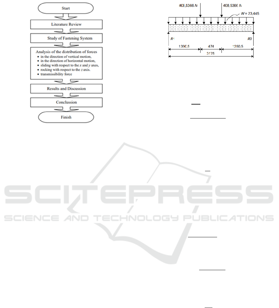
Figure 2: Research flow chart.
4 RESULTS AND DISCUSSION
4.1 Foundation Strength Calculation
for Engine 1
The foundation strength is calculated based on the
maximum bending moment M and the transverse
shear force V. The data needed for this calculation
are:
• Weight of engine and engine bed = 23.445 N
• Transmission Force (F
TR1
) = 1,610.7009 N
4.1.1 2-Points Fastening
Load Distribution of Engine 1 at the engine
foundation with 2-point fastening has seen in Figure
3. The maximum bending moment is calculated using
the following equation:
𝑀𝑃
.𝑎
(6)
Where,
P
tr
: ¼ (engine and engine bed +
transmission force)
a : 1,350.5 mm
then,
M = ¼ (23.445+1,610.7009) . 1,350.5
= 551,728.7 N.mm
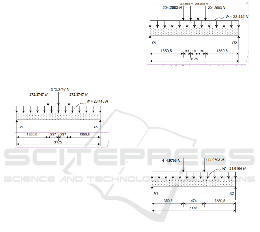
Figure 3: Load distribution at the foundation with 2-
points fastening
.
Reaction to support (R) can be calculated as
follows:
𝑅
8𝑀
2𝐿
8 ∗ 551,728.7
2 ∗ 3,175
695.09 N
(7)
The transverse shear force V is equal to the value
of R (V = R), i.e. V = 695.0912 N. To determine the
maximum bending stress, the equation is:
𝑠
𝑀
𝑍
(8)
Where,
Z
= bh
2
/6 (9)
Noted that,
b = 220 mm
h = 225 mm
then,
𝑍
220 ∗ 225
6
1,856.250 mm
Therefore,
𝑠
551,728.7
1,856,250
0.297MPa
For the maximum shear stress (s
s
) of a rectangle:
𝑠
3𝑉
2
𝐴
(10)
Where,
A = (220)(225)
= 49,500 mm
2
Therefore, the shear stress can be determined as
follows:
s
s
= 0,021 MPa
The closest quality of wood is used to determine
the permitted bending stress (s) and shear stress (s
s
),
namely pine ponderosa No. 1, with s permission = 6.4
Effect of Engine Fastening Points’ Amount on the Vessel’s Foundation towards Vibration Transmissibility Value in Traditional Vessel
Structures
113
MPa and s
s
permission = 0.45 MPa, approved by
National Design Specification. From the calculation
results, it can be seen:
𝑠𝑠
0.2976.4
MPa
𝑠
𝑠
0.0210.45
MPa
From these results, it can be seen that the
foundation is still within the limits of permission in
accepting the load of working on it. Other calculation
results can be seen in Table 3.
4.1.2 3-Points Fastening
Load Distribution at the engine foundation with 3-
points fastening has seen in Figure 4.
Figure 4: Load distribution at the foundation with 3- points
fastening.
The calculation is done in the same way as 2-
points fastening, where the results can be seen in
Table 3.
4.1.3 4-Points Fastening
Load distribution at the engine foundation with 4-
points fastening has seen in Figure 5. The calculation
is done in the same way as above, where the results
can be seen in Table 3.
4.2 Foundation Strength Calculation
for Engine 2
The foundation strength is calculated based on the
maximum bending moment M and the transverse shear
force V. The data needed for this calculation are:
• Weight of engine and engine bed = 21.916 N
• Transmission Force (F
TR1
) = 1,638.0009 N
4.2.1 2-Points Fastening
The maximum bending moment is calculated using
equation (6), therefore,
M = 560,429.6 N.mm
Reaction to support (R) (Equation 7):
R = 706.053 N
Figure 5: Load distribution at the foundation with 4- points
fastening.
Figure 6: Load distribution at the foundation with 2- points
fastening
.
senta 2019 - The International Conference on Marine Technology (SENTA)
114
The transverse shear force V is equal to the value of
R (V = R), i.e., V = 706.053 N.
Equation (6) is used to determine the maximum
bending stress as follows:
Where,
Z = 1,856.250 mm
3
Therefore,
maks s = 0.3019 MPa
Equation (10) was used to determine the maximum
shear stress (ss) of a rectangle:
Where,
A = 49,500 mm
2
thus,
s
s
= 0.0214 MPa
From the calculation results, it can be seen:
𝑠𝑠
0.30196.4
MPa
𝑠
𝑠
0.02140.45
MPa
From these results, it can be seen that the
foundation is still within the limits of permission in
accepting the load of working on it. Other calculation
results can be seen in Table 3.
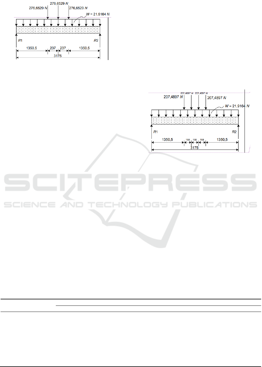
4.2.3 3-Points Fastening
Load distribution of engine 2 to the engine foundation
with 3-points fastening has seen in Figure 7. The
calculation is done in the same way as above, where
the results can be seen in Table 3.
4.2.4 4-Points Fastening
The distribution of loading at the engine foundation
with 4-points fastening has seen in Figure 8. The
calculation is done in the same way as above, where
the results can be seen in Table 3.
Figure 8: Load distribution at the foundation with 4- points
fastening
.
5 CONCLUSIONS
Based on the comparison, we can see that the shear
force's magnitude and the bending moment have
decreased. This change indicates that dissipation
occurs with the addition of the amount of fastening.
The results have shown the reduction of the
transmission force to the foundation. By itself, the
value of amplitude to the base decrease due to the
work of the system.
This study's results reinforce the results of
previous studies where the damping and stiffness
values were varied to obtain the smallest amplitude
value. The increase in stiffness through the number of
Figure 7: Load distribution at the foundation with 3- points
fastening
.
Table 3: Results of foundation strength calculations.
Description Unit
En
g
ine 1 En
g
ine 2
2-
p
oint 3 point 4-
p
oint 2-
p
oint 3 point 4-
p
oint
m kg 23.446 23.446 23.446 21.916 21.916 21.916
F
TR
N 1,610.71 1,610.71 1,610.71 1,638.00 1,638.00 1.633001
P
TR
N 408.537 272.358 204.268 414.979 276.653 207.49
M
N 551728.7 367,319.10 275,364.30 560,429.60 373,619.70 230.2143
R
N 695,091 463.394 347.546 706.053 470.702 353.027
V
V 695,091 463.394 347.546 706.053 470.702 353.027
Z
mm
3
1,856,250 1,356,250 1,856,250 1,856,250 1,856,250 1,856,250
s
0.29723 0.19815 0.14861 0.30392 0.20128 0.0151
s
s
0.02106 0.01404 0.01053 0.0214 0.01426 0.0107
Effect of Engine Fastening Points’ Amount on the Vessel’s Foundation towards Vibration Transmissibility Value in Traditional Vessel
Structures
115

fixing points makes this research more optimal for
reducing amplitude. The number of fixing points
affects the value of the distribution of bending stress
(s) and shear stress (ss). The increasing of the
fastening point reduces the value of bending stress (s)
and shear stress (ss).
Based on the calculations' results with the two,
three, and four-point fastening models, the smallest
amplitude value is obtained at the four-point drafting.
Several other factors also affect increasing the value
of structural stiffness apart from those in this study.
The type of material and the dimensions of the
foundation also affect the amplitude value. Further
research can be done on this matter to support the
research results that have been done.
REFERENCES
Ariana, I.M. 1998. Getaran Permesinan Kapal: Handout
FTK, Surabaya: Institut Teknologi Sepuluh Nopember.
Ghozali, M. 2007. Analisa Getaran Pondasi Motor
Pengerak Kapal Ikan Tradisional Tipe Outboard
Engine, Surabaya: Institut Teknologi Sepuluh
Nopember.
Hedge, A. 2007. Human Vibration
http://ergo.human.cornell.edu.com.
Hopcroft, R., and Skinner, M. (2005). Human Vibration,
http://dspace.dsto.defence.gov.au/dspace/bitstrea
m/1947/4336/1/DSTO-TR-1756.pdf.
Inman, D. J. (1996). Engineering Vibration, International
Editions, Prentice Hall Inc., USA.
Inman, D. J. (1996). Engineering Vibration, International
Editions, Prentice Hall Inc., USA.
Lekatompessy, D.R. (2003) Tinjauan Pengaruh Getaran
Mesin Terpasang Terhadap Kekuatan Konstruksi
Pondasi Kapal Tradisional, Thesis, Institut Teknologi
Sepuluh Nopember, Surabaya.
Lekatompessy, D. R., Sulaiman, O. O., Manuhutu, F., de
Lima, E. J., and Manuputty, M. (2013). Rubber as an
Effective Vibration Absorber of Outboard Engine at
Small Traditional Fishing Boats from the Human
Health and Safety Point of View. Journal of
Engineering Computers & Applied Sciences 2 (2): 7–
12.
Seto, W. W. (1992). Getaran Mekanis (Machine Vibration).
Translate by Sebayang Darwin, Erlangga, Jakarta.
senta 2019 - The International Conference on Marine Technology (SENTA)
116
