
Effect of Sisal Fiber Direction Angle on Physical and Mechanical
Properties of Composites
Perdinan Sinuhaji
1*
, Awan Maghfirah
1
, Prisila Dinanti
1
and Willy Arti
1
1
Department of Physics, Universitas Sumatera Utara, Medan, Indonesia
Keywords: Composites, Fiber Direction Angle, Physical Properties, Mechanical, Epoxy Sisal-resin Fiber.
Abstract: Research on the effect of sisal fiber angle on density, water absorption, porosity, flexural strength, impact
strength, and tensile strength of sisal-epoxy resin composite fibers. Composites are made by hand lay out
method in the composition of sisal fiber material: epoxy resin = 10 wt% : 90 wt% with the fiber angle
orientation layout at: 0°, 30°, 45°, 60°, 90°. Composite properties obtained have an average density of 1.2
g/cm
3
, water absorption increases linearly, and porosity of composites rises linearly to changes in angle
increment which is greater and has flexural strength, impact strength, composite tensile strength linearly
decreases to changes in the incremental angle. Optimal mechanical properties occur at the angle of fiber 0°,
this is due to the long fiber direction, in the direction of the tensile force which is at 0°. The length of each
fiber at 30°, 45°, 60°, 90°, will have lower mechanical properties, due to the shorter load distribution.
1 INTRODUCTION
Composite is a material that is formed from a
combination of two or more materials that are macro
and insoluble to one another (GuruRaja, 2013). One
forming element is called an amplifier and one
element is called a binding (GuruRaja, 2013).
Reinforcing agents can be in the form of fibers,
particles, or flakes (GuruRaja, 2013)(Hodzic,
2013).The role of the matrix in the composite material
is to give shape to the composite part, protecting the
reinforcement and perfection of the material, together
with the reinforcement (Parandoush, 2017).
Composite materials are used for cars, ships,
airplanes, sporting goods and so on (GuruRaja, 2013).
The nature of composite materials is strongly
influenced by the nature and distribution of the
constituent elements, as well as the interactions
between the two
(Hodzic, 2013). Important parameters
that influence the nature of the composite material are
the shape, size, orientation and distribution of the
amplifier (filler) as well as the characteristics of the
matrix
(Pickerig, 2015). The mechanical properties of
composite materials depend on the nature of the
constituent materials (Pickerig, 2015)
. The main role
in fiber-reinforced composites is to move stress
between the fiber, provide resistance to the
environment, maintain the surface of the fiber,
mechanical and chemical effects (Hodzic, 2013). The
contribution of fiber is largely influential on the
mechanical strength of composite materials (Pickerig,
2015).
The choice of natural fibers and matrix materials,
fiber orientation, fiber arrangement is one of the
significant ways to increase the strength of
composites (Woo, 2006). Testing the angle of
orientation of the fiber is very important so it takes a
lot of effort to do research (GuruRaja, 2013)
(Woo,
2006)
(Marin, 2019). Therefore, researchers are
interested in knowing the physical and mechanical
properties of making sisal fiber composite boards
with epoxy resin with orientation toward sisal fiber at
0°; 30°; 45°; 60°; 90° is expected to produce
composites that are stronger, tougher, stronger and
meet quality standards so that they can be utilized by
industry (Naraganti, 2017) (Marin, 2019) (Kretsis,
1987).
Environmentally friendly composite materials
based on natural fibers can be obtained around the
environment (Pickerig, 2015)
. Natural fibers are now
widely used because of their abundance and are so
cheap that they are often used as reinforcing materials
such as kenaf, abaca, rosella, straw, sisal and many
natural fibers which are quite abundant in Indonesia
and can be renewed (Hodzic, 2013). Epoxy resins
have wide uses in the chemical, electrical,
mechanical, and civil chemical industries as
86
Sinuhaji, P., Maghfirah, A., Dinanti, P. and Arti, W.
Effect of Sisal Fiber Direction Angle on Physical and Mechanical Properties of Composites.
DOI: 10.5220/0010136700002775
In Proceedings of the 1st International MIPAnet Conference on Science and Mathematics (IMC-SciMath 2019), pages 86-89
ISBN: 978-989-758-556-2
Copyright
c
2022 by SCITEPRESS – Science and Technology Publications, Lda. All rights reserved
adhesives, coating paints, and printed objects
(Baheshtizadeh, 2018)
(Kretsis, 1987). Besides having
high strength, epoxy resin also has good chemical
resistance (Baheshtizadeh, 2018) (Kretsis, 1987).
Sisal is the most widely used natural fiber, most of
this economical and renewable material has not been
fully utilized Naraganti,(Hodzic, 2013). At present
the main use of sisal is limited to the fields of marine
and agriculture (Naraganti, 2017). Sisal fiber
applications include the manufacture of yarn, ropes,
mats, fish nets (Naraganti, 2017).
2 MATERIALS
The material used is sisal fiber obtained from
Surabaya sisal rope suppliers, epoxy resin and epoxy
hardener obtained from the chemical store PT. Justus
Kimiaraya. The tools used are digital balance sheet,
hot press, 2 pieces of iron plate, sample molds,
GOTECH Universal Testing Machine (UTM),
GOTECH Impactor.
3 METHODS
The selection of sisal fiber, described to obtain the
smallest strands used as reinforcement, is then
prepared by epoxy resin and hardener in a ratio of 2:
1. Made fiber mass: epoxy resin mass = 10 wt%: 90
wt%, then calculate the fiber mass and epoxy resin
mass. prepare the mold, then arrange the direction of
the fibers at 0°, 30°, 45°, 60° and 90° on each
composite board, glue together, mix the resin and
hardener into the measuring cup, stir evenly, pour the
resin and hardener mixture into the mold that has been
glued to the fiber, evenly, closed the mold using a
second iron plate coated with aluminum foil and
waxed. Furthermore, the mold is placed on a hot
press, pressurized 5 tons at a temperature of 90°C
within 20 minutes. Then the sample is removed,
conditioned 1 x 24 hours. Composite boards are cut
to standard test sizes, and samples are made in the
same way at an angle of 30°; 45°; 60°; 90°, then each
sample is ready to be tested.
4 RESULTS AND DISCUSSION
4.1 Density Test
Testing the density of sisal-epoxy fiber composites is
first weighed on the composite mass, then the sample
volume is measured to be able to calculate the
composite density. The results of the measurement of
composite density with the orientation angle of the
fiber 0°; 30°; 45°; 60°; 90° shown in the following
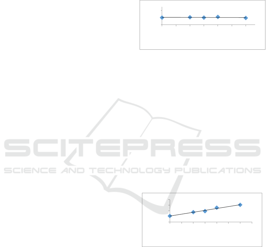
figure 1.
Figure 1: Density vs fiber direction angle.
From Figure 1 above it can be analyzed that the
relationship between density and fiber direction angle
is 0°; 30°; 45°; 60°; 90° tends to be linearly flat, this
is due to the fact that the mass of the fiber remains for
each change in direction angle of the fiber at 0°; 30°;
45°; 60°; 90°, so that it will produce a fixed composite
density. The average density of sisal-epoxy fiber
composites is 1.2 g/cm
3
.
4.2 Absorption Water Test
Composite water uptake was carried out to determine
the percentage of water absorbed by the composite
soaked in water for 24 hours. Water absorption tests
have been carried out on composites with each fiber
angle orientation 0°; 30°; 45°; 60°; 90°. The results of
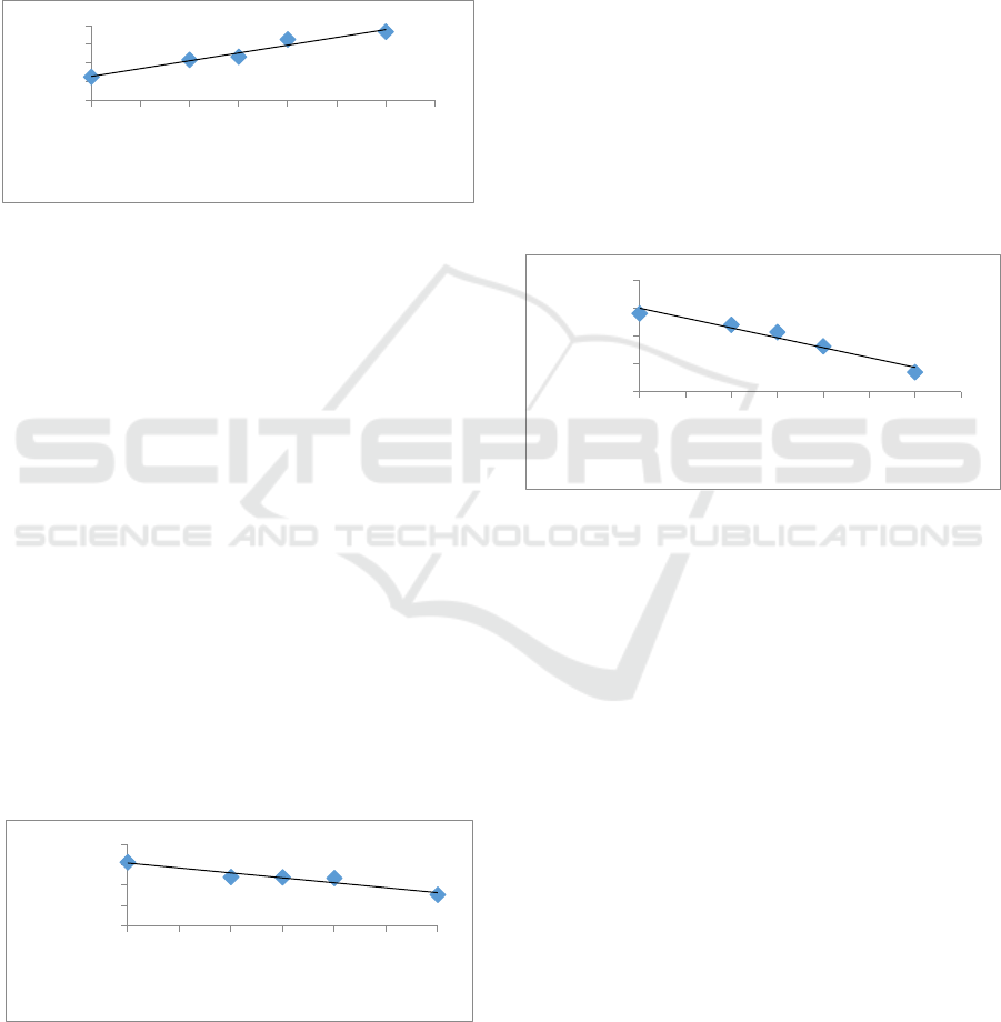
the composite water absorption test are shown in
Figure 2 below.
Figure 2: Absorption water vs fiber direction angle.
From Figure 2 above it can be analyzed that the
relationship between composite water uptake and
fiber direction angle at 0°; 30°; 45°; 60°; 90° tends to
rise linearly, this is due to the arrangement of the
laying direction of the fiber at 0°; 30°; 45°; 60°; 90°
has a fixed mass, but when cutting a composite board
sample results in the cut section of the incision having
fibers not covered by epoxy resin getting bigger.
y=‐7E‐05x+1,207
R²=0,0385
1
1,2
1,4
0 153045607590
Density (g/cm
3
)
Fiber direction angle (°)
y=0,0451x+2,115
R²=0,9831
0
2
4
6
8
0 153045607590105
Absorbtion water
(%)
Fiber direction angle (°)
Effect of Sisal Fiber Direction Angle on Physical and Mechanical Properties of Composites
87
4.3 Porosity Test
Composite porosity test is performed to determine the
ratio between pore volume to total volume of the
composite. Porosity test has been carried out with the
orientation of sisal fiber angle at 0°; 30°; 45°; 60°;
90°, the results of the composite porosity test with the
orientation angle of the sisal-epoxy fiber are shown in
Figure 3 below.
Figure 3: Porosity vs fiber direction angle.
From Figure 3 above it can be analyzed that the
relationship of porosity of the composite with the
fiber direction angle at 0°; 30°; 45°; 60°; 90°, tends to
increase linearly, this is due to the increase in the
direction angle of the composite fiber at the same
mass and when cutting the test sample will cause the
porosity of the composite to rise. At the incision of
the sample trapped air between sisal fibers, can not be
pressed out and form air bubbles or voids so
susceptible to porous.
4.4 Flexural Strength Test
The flexural strength test uses the GOTECH
Universal Testing Machine type Al-7000M, to
determine the resistance of the composite to loading
at three bending points and also to determine the
elasticity of the composite. The results of the
composite flexural strength test with the fiber
direction angle at 0°; 30°; 45°; 60°; 90°, shown in
figure 4 below.
Figure 4: Flexural strength vs fiber direction angle.
From Figure 4 above it can be analyzed that the
relationship between the flexural strength of the
composite with the fiber direction angle 0°; 30°; 45°;
60°; 90° tends to decrease linearly. This is because
the load from the matrix to the fiber is smaller and the
interfacial bond is even stronger, because the length
of the fiber at 0° gives higher strength than the shorter
fiber length. Composite flexural strength at the angle
of fiber 0o has the greatest flexural strength of 62.72
MPa, compared to other flexural strengths due to the
long pieces of fiber arranged on the 0° composite
being longer than the fibers arranged at an angle of
30°, 45°, 60°, and 90°.
4.5 Impact Strength Test
The test samples used were rectangular in accordance
with ASTM D256. Impact testing is done with the
GOTECH Impactor tool. Strong composite impact
test results with fiber angles at 0°; 30°; 45°; 60°; 90°,
shown in figure 5 below.
Figure 5: Impact strength vs fiber direction angle.
From Figure 5 above we can analyze the impact
of the strong impact on the fiber direction angle at 0°;
30°; 45°; 60°; 90°, tends to be linearly decreased, this
is because the shorter fiber length will have a bond
between and the matrix is much lower than the fiber
length at 0°. The maximum impact strength is 27.97
J/mm
2
and there is a decrease in impact strength at
each decrease in fiber direction angle.
4.6 Tensile Strength Test
The test sample used is rectangular in shape, the size
is adjusted to ASTM D 638-01 standard. Flexural
strength test is performed using the GOTECH
Universal Testing Machine type Al-7000M. The
results of the composite tensile strength test with a
fiber angle of 0°; 30°; 45°; 60°; 90°, presented in
Figure 6 below.
y=0,0555x+2,565
R²=0,9589
0
2
4
6
8
0 153045607590105
Porosity (%)
Fiber direction angle (°)
y=‐0,3249x+61,897
R²=0,9168
0
20
40
60
80
0 153045607590
Flexuralstrength
(MPa)
Fiber direction angle (°)
y=‐0,235x+29,88
R²=0,9537
0
10
20
30
40
0 153045607590105
Impact strength
(J/mm
2
)
Fiber direction angle (°)
IMC-SciMath 2019 - The International MIPAnet Conference on Science and Mathematics (IMC-SciMath)
88
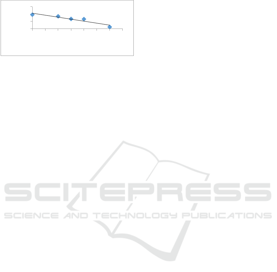
Figure 6: Tensile strength vs fiber direction angle.
From Figure 6 above it can be analyzed that the
relationship of flexural strength to the angle of
orientation of the fiber decreases linearly, this is due
to the change in the angle of direction of the fiber at
0°; 30°; 45°; 60°; 90° gives a lower tensile strength,
due to the load received by the fiber at each lower
angle, because the distribution of load to the fiber will
decrease lower at a greater fiber angle. The greatest
tensile strength of composites occurs at a direction
angle of 0o by 19.28 MPa, and a decrease occurs due
to the length of the fibers arranged at 0° longer than
the length of fibers arranged at an angle of 30°; 45°;
60°; 90°, so the distribution of the load on the
composite decreases.
5 CONCLUSIONS
From the results of the study the influence of the
direction angle of sisal fiber with composite epoxy
resin can be concluded that:
Sisal fiber composites - epoxy resin with fiber mass
ratio: epoxy resin mass is 10 wt%: 90 wt% has an
average density of 1.2 g/cm
3
, water uptake rises
linearly and porosity also rises linearly for each
change in direction angle fiber at 0°; 30°; 45°; 60°;
90°. The flexural strength of the composite has
decreased linearly, the impact strength of the
composite also has decreased linearly and the tensile
strength has also decreased linearly at each change in
the angle of direction of the fiber at 0°; 30°; 45°; 60°;
90°. Composite properties at sisal fiber direction
angle with epoxy at 0° shrinkage, 30° angle, 45° angle
and 60° angle, can be used as a car bumper material,
composite flexural strength greater 32 MPa.
REFERENCES
Baheshtizadeh, N., 2018. Three point bending test of
glass/epoxy composite healt monitoring by acoustic
emission.
GuruRaja, M.N. dkk, 2013. Influence of Angle Ply
Orientation on Tensile Properties of Carbon/Glass
Hybrid Composite. J. Miner. Mater. Charact. Eng. 1,
231–235.
Hodzic, A., 2013. Natural Fibre Composites. B. Sci.
Kretsis, G., 1987. A Review of the Tensile, Compressive,
Flex- ural and Shear Properties of Hybrid Fibre
Reinforced Plastics. Composites 18, 13–23.
Marin, J.C., 2019. On the optimal choice of fibre orientation
angle in off-axis tensile test using oblique end-tabs:
Theoretical and experimental studies. Compos. Sci.
Technol. 1–51.
Naraganti, S., 2017. Impact resistance of hybrid fibre
reinforced concrete containing sisal fibres 1–9.
Parandoush, P., 2017. A review on additive manufacturing
of polymer-fiber composite. Compos. Struct. 36–51.
Pickerig, K.L., 2015. A review of recent developments in
natural fibre composites and their mechanical
performance. Composites 98 – 109.
Woo, 2006. Effect of Fiber Aspect Ratio And Area Ratio
Getting To Accuracy Of Intensity Method In Fiber
Orientation Angle Distribution Measurement. KEM
326–328.
y=‐0,1802x+21,237
R²=0,8828
0
10
20
30
0 153045607590105
Tensile strength
(MPa)
Fiber direction angle (°)
Effect of Sisal Fiber Direction Angle on Physical and Mechanical Properties of Composites
89
