
Dynamic Behavior Analysis of Porous Saw Floating Breakwater
under Regular Waves
Sujantoko, E. B. Djatmiko, W. Wardhana, H. D. Armono and Wahyudi
Department of Ocean Engineering, Institut Teknologi Sepuluh Nopember, Surabaya, Indonesia
Keywords: Floating Breakwater, Porous, Motion, RAO.
Abstract: Porous saw floating breakwaters are floated and tethered breakwaters for coastal protectors with typical steep,
deep, and relatively large choppy contours, designed with saw porous, to be able to absorb waves efficiently
and effectively. A proposed numerical model was developed for the porous saw type, while the model for the
pontoon and the saw type will be used as a comparative study. All types of the structure breakwaters were
physically placed inside the flume tank in which the direction of waves was perpendicular (to the structure)
with 3 cm height and 1.1 seconds of period conducted in 41 cm depth of water. The numerical model shows
that the Response Amplitude Operators (RAO) only affect the sway, heave, and roll motions. The porous saw
floating breakwater demonstrates the smallest RAO value among other types i.e. sway 0.66 cm/cm, heave 2.1
cm/cm, and roll 0.86 deg/cm. It means the porous saw type more advantages since the ability to absorb the
wave. Moreover, some of the wave energy will be reduced when the wave passes through the structure.
Therefore, the wave energy received by the structure and the mooring rope becomes smaller.
1 INTRODUCTION
In recent years, many sectors attempt to manage and
utilize the Indonesian coastal region. Such as
industry, trade, transportation, housing, and the
tourism sector. As population growth and increasing
socio-economic development activities, the "value"
of the coastal region continues to grow. Coastal areas,
despite their high economic value, are vulnerable to
many threats. One serious threat encountered is
abrasion, causes a reduction in coastal areas. It may
happen because of the large amount of wave energy
comes directly to the coast without any absorption
beforehand.
Preventing the negative effects caused by
abrasion, it is very important to build and install the
coastal protection structures to reduce wave energy
towards the coastal area. One of the coastal protection
structures that protect from abrasion and erosion is a
breakwater, a structure was built to protect the area
behind it from the wave attacks. There are two types
of breakwaters, namely fixed breakwater and floating
breakwater, both are built depending on the normal
water level elevation and tidal conditions in which
the structure is placed. Floating breakwater offers the
level of protection needed when working in deeper
waters with exposure to natural resources that are
stronger than conventional types of the breakwater.
Floating breakwater applying the concepts of
reflection, dissipation, and transformation to reduce
wave energy so that it can weaken the up-coming
wave to an acceptable level (Morey, 1998). This
breakwater is a floating structure on a limited draft
and depends on the interaction of building structures
at the top of the water column. Moreover, another
advantage of floating breakwater against the fixed
breakwater, the efficiency does almost not depend on
the tides and sea-level rise, then the impact to the
environment is low, the cost of structure
construction, installation and removal are low, short
time for installation, and ability to reset the layout if
there are changes in the future (Ruol et al. , 2012).
However, as a floated structure, then a mooring
system placed on the seabed (Fousert, 2006).
In general, floating breakwaters reduce the
surface waves through the mechanism of reflection,
destroying the movement of water particles and
attenuation of viscosity. When the waves hit the
structure, energy will be reflected, scattered, and
partially muted by the structure. The greater the wave
energy absorbed, the higher the intensity of the
following structure's motion. Since most of the wave
energy will be converted into motion energy. The
212
Sujantoko, ., Djatmiko, E., Wardhana, W., Armono, H. and Wahyudi, .
Dynamic Behavior Analysis of Porous Saw Floating Breakwater under Regular Waves.
DOI: 10.5220/0010119102120217
In Proceedings of the 7th International Seminar on Ocean and Coastal Engineering, Environmental and Natural Disaster Management (ISOCEEN 2019), pages 212-217
ISBN: 978-989-758-516-6
Copyright
c
2021 by SCITEPRESS – Science and Technology Publications, Lda. All rights reserved
amount of energy absorbed is largely determined by
the magnitude of the cross-sectional area of the
structure relative to the perpendicular direction of the
incident wave. Therefore, a floating breakwater
design with minimum cross-section and interaction
effect is an important reference for producing designs
with minimum responsiveness. Such conditions can
be achieved with porous surface conditions.
Based on the concept of maximum energy
dissipation due to reflections and minimum energy
trajectories that pass through the structure, the
floating breakwater research continues to develop to
find better performance. The number of researchers
has conducted a study on the floating breakwater with
porous types, namely porous pontoon (Lee & Ker,
1997; Williams & Li, 1998; Wang & Sun, 2010),
porous boxes (Stainissie & Drimer, 2003; Koutandos
& Prinos, 2011; Zeng et al., 2018), porous plates
(Chwang & Dong, 1984; Wang & Ren, 1993; Cho,
2016; Fang at al., 2018), porous cylinder (William et
al., 2000; Zhao et al., 2010; Shih, 2012).
This research will study the porous floating
breakwater. This type of structure also reduces
extreme wave loads which can affect the performance
of floating structures. In an impermeable form, the
structure will receive the maximum wave force so
that it will transfer the wave energy to the mooring
rope. This undesirable condition since mooring ropes
will receive large loads so that the structure remains
stable receiving wave force. The response of
structural motions as a result of wave loads will affect
the performance of the structure, i.e. reflection and
transmission of waves. Therefore, during the design
stage, it is necessary to predict the structure's motion
to produce a small wave attenuation. Numerical
simulations will be carried out to determine the
characteristics of the 6 degrees of freedom structure
motions using the Ansys Aqwa Module.
2 METHOD OF RESEARCH
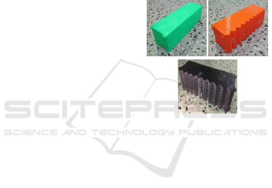
2.1 Floating Breakwater Design
The material used in the floating breakwater model is
High-Density Polyethylene (HDPE) with a density of
960 kg/m
3
. Figure 1 shows the pontoon, porous saw,
and saw type floating breakwater have the same
dimensions (length 20 cm, height 6 cm and width 6
cm). The types are slightly different, the porous saw
type has a pore, which is penetrated the structure
from the front to the back and there is also a triangle
shape lined up in the front of the structure.
In the porous saw type, the pipes are used so that
the front and rear sides of the breakwater are
perforated. The pipe used has an outside diameter of
0.4 cm. These three breakwater types above are floats
with a 4 cm draft. The pore in the porous saw type
floating breakwater is take up to 5% area of the
overall area in the side of the structure. The
difference between these three models requires the
thickness of the porous saw type floating breakwater
to be 0.36 cm to keep drafts are the same. The
reduction was caused by the loss of buoyant force due
to a hole in the floating breakwater.
Figure 1: Floating breakwater (a) type pontoon, (b) saw and
(c) porous saw.
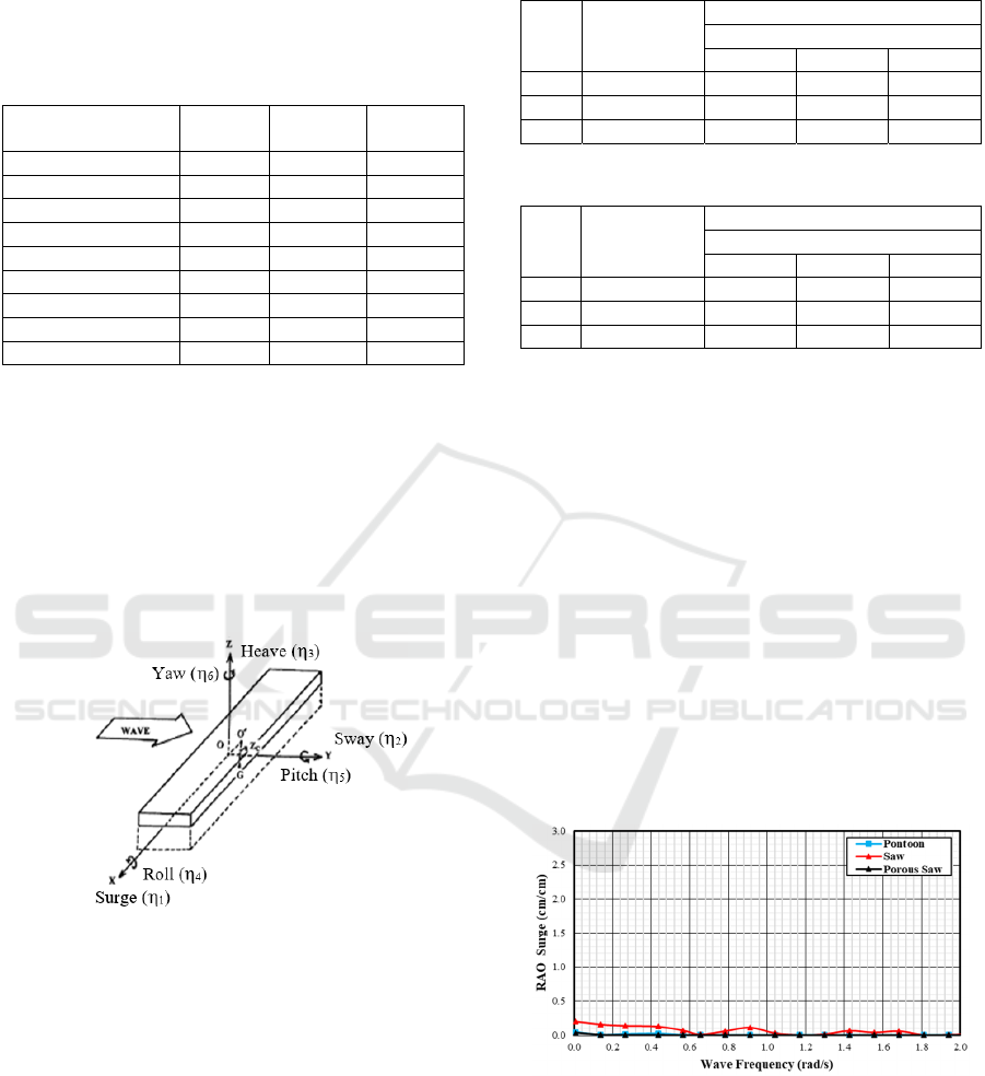
2.2 Hydrostatic Parameters
A series of floating breakwater models arranged in 3
directions longitudinal to the width of the flume tank.
The hydrostatic parameters in this numerical
simulation are used as a basis for measuring the
model validation. Based on the dimensions of the
floating breakwater model, it can be determined the
volume of the types of a pontoon, saw, and porous
saw respectively 2266.58 cm
3
, 2487.5 cm
3
, and 2274
cm
3
. The mass of the floating breakwater can be
determined by multiplying the volume by the density
of HDPE so that the mass of the floating breakwater
type of pontoon, saw, and porous saw is 1457 gr,
1592 gr, and 1535 gr respectively. The third
dimension of this structure is designed to have a draft
of 4 cm.
The initial step before developing a numerical
model is calculating the center of gravity for each
structure. The value of the gravity center in the
floating structure is very important to determine the
stability of the floating breakwater. The center of
gravity calculation is done by dividing floating
(
a
)
(
b
)
(
c
)
Dynamic Behavior Analysis of Porous Saw Floating Breakwater under Regular Waves
213
breakwater into several parts. Then, determining the
value of inertia and the radius of structure gyration.
Complete data on hydrostatic parameters are shown
in Table 1.
Table 1: Hydrostatic data floating breakwater.
Hydrostatic
Parameters
Pontoon Saw
Porous
Saw
Vol. Dis
p
l.
(
cm
3
)
2266.6 2487.5 2274
Massa
(g
r
)
1457 1592 1535
Ixx 3822 4498.9 4387.6
Iyy 40812 44553.75 44546.85
Izz 43197 47276.3 47253.4
Kxx 1.62 1.68 1.64
K
yy
5.29 5.29 5.29
Kzz 5.45 5.45 5.45
WPA (cm
2
) 360 372 372
2.3 Validation of the Hydrostatic Model
Numerical simulations to determine the response of
floating breakwater motion are performed by
computational fluid dynamics with the ANSYS/
AQWA hydrodynamic simulation software. Figure 2
shows the layout of the model scenario with the
direction of the incident wave perpendicular to the
structure.
Figure 2: Degree of freedom of floating structures (Das &
Das, 2005).
Before conducting the structural motion analysis,
the floating breakwater model must be validated to
find out the floating breakwater by the conditions in
the analytical calculation. Important hydrostatic
parameters that will be used for the validation of this
model are the volume displacement and water plane
area. Based on The American Bereau of Shipping
(1998), the validation is a maximum of 2% and for
other provisions a maximum value of 1%. The
calibration results of the model are shown in Table 2
and 3.
Table 2: Validation of numerical models: volume
displacement.
No
Floating
Breakwater
Hydrostatic Parameters
Volume Displacement (cm
3
)
Analytic Numeric Error %
1 Pontoon 1457 1457 0
2 Saw 1657 1657 0
3 Porous Saw 1663.79 1658.28 0.303
Table 3: Validation of numerical models: water plane area.
No
Floating
Breakwater
Hydrostatic Parameters
Water Plane Area (cm
2
)
Anal
y
tic Numeric Error %
1 Pontoon 360 360.01 0.0001
2 Saw 372 371.8 0.002
3 Porous Saw 372 371.8 0.002
3 RESULTS AND DISCUSSION
Numerical simulations of floating breakwater motion
have been done at a depth of 41 cm, a wave period of
1.1 s and a wave height of 3 cm with the direction of
the wave perpendicular to the structure. The results
of numerical simulations are shown in figures 3-8.
The characteristic of surge motion in pontoons,
saw and porous saw floating breakwater in the
direction of waves perpendicular to the structure is
very small and almost close to 0 (Figure 3). Saw type
RAO is the biggest among other types because there
is additional displacement in front of the structure.
Generally in the surge motion, waves to the side do
not have an effect on the occurrence of surge
motions.
Figure 3: RAO Surge numerical prediction of various types
of the floating breakwater.
Sway motion characteristics are almost the same
as the surge motion where the maximum RAO value
is at low frequencies (Figure 4). The highest RAO on
the pontoon is 0.79 cm/cm. At the same frequency,
the maximum RAO for saw-type floating breakwater
is 0.98 cm/cm and porous saw-type RAO is 0.6
ISOCEEN 2019 - The 7th International Seminar on Ocean and Coastal Engineering, Environmental and Natural Disaster Management
214
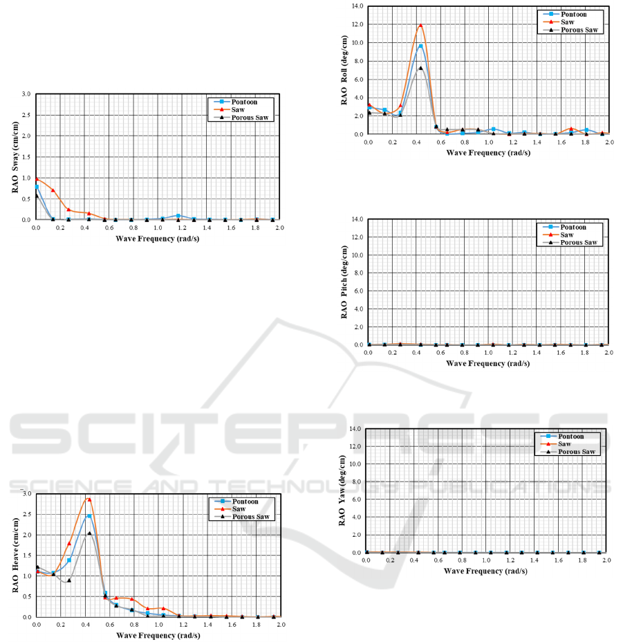
cm/cm. After that, the third RAO floating breakwater
decreases gradually. Sway motion has a higher
maximum value when compared to surge for side
waves because side wave propagation has a great
influence on sway motion.
Figure 4: RAO Sway numerical prediction of various types
of the floating breakwater.
Figure 5 shows the RAO heave motion is an
example to explain dynamic systems that experience
wave excitation. At low frequencies, the three RAO
types of floating breakwater are 1.11 cm/cm, 1.08
cm/cm, and 1.13 cm/cm and gradually increase
towards the resonant region at the natural frequency
of 0.436 rad/s. the largest maximum RAO heave
occurs in the saw type followed by porous pontoon
and gergagi types respectively 2.85 cm / cm, 2.45
cm/cm, and 2.1 cm/cm. After crossing the peak, the
RAO heave will decrease dramatically at high
frequencies.
Figure 5: RAO Heave numerical prediction of various
types of the floating breakwater.
Roll motion is almost the same as the
characteristics of the heave motion (Figure 6). In the
sub-critical region, the motion response represents
the same condition in all types of the floating
breakwater, then increases sharply in the resonant
region and decreases significantly in the supercritical
region. The natural frequency of the roll motion is
0.43 rad/s. The value of the highest response of roll
motion on a saw is 11.86 deg/cm, followed by the
pontoon type of 9.64 deg/cm, and the porous saw is
6.8 deg/cm.
Figure 6: RAO Roll numerical prediction of various types
of the floating breakwater.
Figure 7: RAO Pitch numerical prediction of various types
of the floating breakwater.
Figure 8: RAO Yaw numerical prediction of various types
of the floating breakwater.
In pitch and yaw motions (Figure 7-8), it is not
the same as roll motions which are both rotational
mode motions. However, pitch and yaw motion
intensity is not affected by side and bow waves, so
that the value is 0 or close to 0 so there is almost no
motions response.
Based on numerical simulations obtained floating
breakwaters motion behavior. The condition of a
free-floating structure without a mooring system will
produce a vertical motion mode (heave, roll, and
sway) which is more dominant than the horizontal
motion mode (surge, pitch, yaw). This happens
because all three modes of motion (vertical motion
modes) have a stiffness factor due to harmonic wave
excitation, the presence of this stiffness factor causes
Dynamic Behavior Analysis of Porous Saw Floating Breakwater under Regular Waves
215

the damping factor value to be small so that when the
motion reaches its resonant frequency, the change in
motion characteristics will have a sharply increased
part. Whereas the horizontal motion mode which
does not have a stiffness factor during free-floating
conditions will produce a relatively large damping
factor so that the motion will be damped by the
presence of the damping factor and the horizontal
motion mode does not experience a sharp increase. If
there is an increase in certain parts, then the increase
in the curve is influenced by the coupling effect of
other motions.
6 CONCLUSIONS
This paper compares the dynamic behavior of a
porous saw type floating breakwater with another
types. Numerical studies were carried out with
computation fluid dynamics on models of these
structures at a water depth of 41 cm, wave height of
3 cm, and a wave period of 1.1 seconds. some
findings may be explained as follows:
The surge, pitch, and yaw motion modes are not
affected by side waves so the RAO value is very
small and almost close to 0.
The floating breakwater motion in the direction of
incoming waves perpendicular to the structure
only affects the motion sway, heave, and roll.
Sway motion has a higher maximum value when
compared to surge for side waves because side
wave propagation has a great influence on sway
motion. At the same frequency, the maximum
RAO for saw-type floating breakwater is 0.98
cm/cm, tipe pontoon is 0.79 cm/cm and porous
saw-type RAO is 0.6 cm/cm. After that, the third
RAO floating breakwater decreases gradually.
The largest RAO maximum heave motion occurs
in the saw type followed by the type of pontoon
and porous saw by 2.85 cm/cm, 2.45 cm/cm, and
2.1 cm/cm respectively. After going through the
peak, the RAO heave will decrease dramatically
at high frequencies.
The highest peak value of RAO roll occurs at
natural frequency 0.43 rad / s, in floating
breakwater type of saw, pontoon, and porous saw
of 11.86 deg/cm, 9.64 deg/cm, and 8.6 deg/cm
respectively.
ACKNOWLEDGEMENTS
This work was financially supported by The
Directorate of Research and Community Service,
Sepuluh November Institute of Technology (ITS),
Surabaya in research grand scema: "Basic Research
for Higher Education" dan Author thank the
Department Mechanical Engineering ITS for
providing the facilities of Ansys/Aqwa software.
REFERENCES
Cho, Il-Hyoung, 2016. Transmission coefficients of a
floating rectangular breakwater with porous side plates.
International Journal of naval Architecture and Ocean
Engineering 8, pp. 53-65
Chwang, A.T. and Dong, Z.N., 1984. Wave-trapping due
to a porous plate. Proceedings Fifteenth ONR
Symposium of Naval Hydrodynamics, pp. 407-414.
Das, S.N and Das, S.K.,2005. Mathematical model for
coupled roll and yaw motions of a floating body in
regular waves under resonant and non-resonant
conditions. Applied Mathematical Modelling 29. Pp.
19–34.
Fang, Z., Xiao, L., Kou, Y. and Li, J., 2018. Experimental
study of the wave-dissipating performance of a four-
layer horizontal porous-plate breakwater. Ocean
Engineering, vol. 151, pp. 222-233.
Fousert, M. W., (2006). Floating Breakwater: a Theoritical
Study of a Dnamic Wave Attenuating System. Thesis.
Section of Hydrolic Engineering. Faculty of Civil
Engineering and Geosciences. Delft University of
Technology. Netherland.
Koutandos, E.V. and Prinos, P.E., 2011. Hydrodynamic
characteristics of semi-immersed breakwater with an
attached porous plate. Ocean. Engineering 38, pp. 34-
48.
Lee, C.P. and Ker, W.K., 1997. Interaction of waves and a
porous tension leg platform with an impermeable top
layer. Proceedings Seventh International Offshore and
Polar Engineering Conference, Honolulu, USA, pp.
207-214.
Morey, Bradley J., 1998. Floating Breakwaters Predicting
Their Performance. Thesis. Faculty of Engineering and
Applied Science, Memorial University of
Newfoundland, Canada
Ruol, P., Martinelli, L., and Pezutto, P., (2012).
Experimental and Numerical Investigation of the Effect
of Mooring Stiffness on the Behaviour of π-Type
Floating Breakwaters. Proceedings of The Twenty-
second International Offshore and Polar Engineering
Conference. Greece : 17-22 June.
Shih, Ruey-Syan, 2012. Experimental study on the
performance characteristics of porous perpendicular
pipe breakwaters. Ocean Engineering 50, pp. 53-62.
Stainissie, M. and Drimer, N., 2003. On a freely floating
porous box in shallow water waves. Applied Ocean
Research 25, pp. 263-268.
The American Bereau of Shipping , 1998. Abs Rules for
Building and Classing Mobile Offshore Drilling Units
ISOCEEN 2019 - The 7th International Seminar on Ocean and Coastal Engineering, Environmental and Natural Disaster Management
216

and The 1989 Imo Modu Code. United State Coase
guarrd Alternate Compliant Program.
Wang, K.H. and Ren, X., 1993. Water waves on flexible
and porous breakwaters. Journal of Engineering
Mechanics, ASCE 119, pp.1025-1047
Wang, H.Y. and Sun, Z.C., 2010. Experimental study on
the influence of geometrical configuration of porous
floating breakwater on performance. Journal of Marine
Science and Technology. 18 (4), pp. 574-579.
Williams, A.N. and Li, W., 1998. Wave interaction with a
semi-porous cylindrical breakwater mounted on a
storage tank. Ocean Engineering 25, pp.195-219
Williams, A.N, Li, W and Wang, K.H., 2000. Wang Water
wave interaction with a floating porous Cylinder.
Ocean Engineering 27, pp. 1-28
Zhao, F., Bao,W., Kinoshita,T. and Itakura, H., 2010.
Interaction of waves and a porous cylinder with an
inner horizontal porous plate. Applied Ocean Research,
vol. 32, pp. 252-259
Zheng, Y.N., Liu, X.M., Chen, C.P., Jiang, Y.P. and Zhang,
C.W., 2018. Experimental study on the wave
dissipation performance and mooring force of porous
floating breakwater. International Conference on Civil
and Hydraulic Engineering (IConCHE), IOP Conf.
Series: Earth and Environmental Science 189, 022058
Dynamic Behavior Analysis of Porous Saw Floating Breakwater under Regular Waves
217
