
Hydrostatic Stiffness as Displacement Boundary Condition of
Floating Cylindrical Structural Analysis in Waves
Raditya Danu Riyanto and Shade Rahmawati
Department of Ocean Engineering, Institut Teknologi Sepuluh Nopember, Surabaya, Indonesia
Keywords: Hydrostatic Stiffness, Displacement Boundary Condition, Structural Analysis, Natural Period.
Abstract: Motion analysis is one of the mandatory aspects to predict the performance of a floating structure, as well as
how its structural strength under certain wave load. However, in majority of floating body performance
prediction, the calculation of motion and strength performance is done separately. Practically, engineers
calculate the motion and hydrodynamics forces that work on the structure, then do separate calculations on
the structure to predict structure’s strength. These separate calculations often use assumptions that tend to be
unrealistic, either over-constrained or under-constrained. This paper provides an alternative to the constraint
problem by introducing hydrodynamic stiffness as boundary conditions, instead of using fixed or simply
supported boundary conditions, spring boundary conditions are applied with hydrodynamic stiffness of
floating body properties. It is expected that this model provides a more realistic constraint to the future
analyses. The results achieved are very promising, where the boundary condition resulting a close natural
frequency approximation compared with the analytical calculation. This configuration is hoped to be the
baseline of more complex structure to be carried out in future research, in order to represent a more realistic
structural displacement boundary condition.
1 BACKGROUND
Motion analysis is one of the mandatory aspects to
predict the performance of a floating structure, as well
as how its structural strength under certain wave load.
However, in majority of floating body performance
prediction, the calculation of motion and strength
performance is done separately.
Practical engineering software package tends to
disintegrate calculation of motion and
hydrodynamics forces that work on the structure for
used to assess the strength of particular floating body.
Traditionally, engineers consider the ship
structure as fixed ends beam (Okumoto, et al., 2009)
or simple beam (Molland, 2008).
Several researches on analytical level proposed
the methods to incorporate ‘sea springiness’ of
floating body during strength analysis. There are
researches conducted to integrate Computational
Fluid Dynamics (CFD) and Finite Element Analysis
(FEA) via Fluid Structure Interaction (FSI) software
packages. ANSYS, for instances, is one of the
established software packages that used for this
intention. In maritime application, various vessel
forms has been used as object. For example,
composite ship structures (Ma & Mahfuz, 2012),
horizontal cylinder (Raja, 2012) and ocean energy
harvesting device (Agamloh, et al., 2008). Several
open source software such as OpenFoam has also
been used for the same intention. Wave-structure
interaction method has been developed using
OpenFoam (Chen, et al., 2014).
Still, the performed researches are still focused on
the fluid interaction and tend to disregard the
displacement boundary condition aspects. Majority of
the those only consider the displacement boundary
condition as buoyancy versus gravity only.
Recent studies provide the hydrostatic stiffness
for linear hydroelasticity. The explicit formulation for
the complete hydrostatic stiffness for flexible floating
structures at rest in calm water is derived based on a
consistent linearization of the external hydrostatic
pressure and the internal structural stresses (Huang &
Riggs, 2000). It is also found that the hydroelasticity
formula deals with more terms, and, that under some
assumptions, it is reduced to the known complete
restoring stiffness (Senjanović, et al., 2011).
This paper introduces the practical hydrostatic
stiffness to be used directly as displacement boundary
condition of rigid floating body. Analytical
Riyanto, R. and Rahmawati, S.
Hydrostatic Stiffness as Displacement Boundary Condition of Floating Cylindrical Structural Analysis in Waves.
DOI: 10.5220/0010058501310137
In Proceedings of the 7th International Seminar on Ocean and Coastal Engineering, Environmental and Natural Disaster Management (ISOCEEN 2019), pages 131-137
ISBN: 978-989-758-516-6
Copyright
c
2021 by SCITEPRESS – Science and Technology Publications, Lda. All rights reserved
131

calculation is introduced as an approach to assess the
application of ground spring to a floating cylinder.
This method is hoped to be an applied practical guide
to model a better and more realistic displacement
boundary conditions for those who cannot afford the
luxury of FSI study.
The proposed method has been initially
developed by American Bureau of Shipping, depicted
at ABS Floating Production Installation (ABS, 2014),
only for ship shaped structures. Authors inspired by
related theory explained at ABS FPI Part 5A, Chapter
3, Appendix 4, Point 17, to be used as basis of so-
called analytical-practical approach of cylindrical
floating structure’s displacement boundary condition.
2 UNCOUPLED
HYDRODYNAMIC MOTION
Based on classical theory as commonly known, the
free-floating body has six degree of freedom in
hydrodynamics motion, namely (Bhattacharya,
1978):
1 Surging = motion backward and forward
in the direction of ship travels
2 Swaying = athwartship motion of ship
3 Heaving = motion vertically up and down
4 Rolling = angular motion about
longitudinal axis (X axis).
Traditionally, the angular
motion alternating from
portside to starboard and vice
versa
5 Pitching = angular motion about the
transverse axis (Y axis).
Traditionally, the angular
motion alternating from bow to
stern and vice versa
6 Yawing = angular motion about the
vertical axis (Z axis)
Above list of motion is illustrated by Figure 1
below
Figure 1: Six Degree of Freedom Hydrodynamic Motion.
2.1 Uncoupled Hydrodynamic Motion
of Floating Cylinder
In this paper we limit the discussion only for
cylindrical structure, which is a bi-symmetrical
structure. Hence, the aforementioned hydrodynamic
motion can be reduced due to similarities, into
following motions:
1. Surging = swaying, with similar X and Y
translation motion.
2. Pitching = rolling, with similar X and Y
rotation motion.
3. Yawing, due to the bi-symmetrical structure,
the Z rotation is considered negligible.
Figure 2: Floating Cylinder Motion.
Figure 2 above explains the considered motions
of floating cylinder. As it can be seen, letter (a) coded
the heaving motion, while (b) coded the rolling
motion, and finally we have (c) coded for swaying
motion. (a) and (c) are the translational motions of the
cylinder, with equation described below:
𝑚𝑢+𝑐𝑢+𝑘𝑢= 𝐹
𝑡
(1)
Where:
𝑚𝑢 = translational inertial force
𝑐𝑢 = translational damping force
ku = translational restoring force
𝐹
𝑡 = translational excitation force
Inertial force for translational motion, is present
when the cylinder is in oscillatory motion, consist of
m (cylinder mass plus hydrodynamic added mass)
multiplied by 𝑢, the motion acceleration for
translational.
Damping force, is the force to resist the motion.
This force consists of damping coefficient c and
translational velocity, 𝑢.
Restoring force is the spring force that brings
back the cylinder into its equilibrium position.
ISOCEEN 2019 - The 7th International Seminar on Ocean and Coastal Engineering, Environmental and Natural Disaster Management
132

Restoring force is composed of k, the hydrostatic
stiffness of the motion, multiplied by u for
translational motion, which is the translation of
cylinder’s Centre of Gravity (CoG)
Furthermore, (b) is the rotational motion of the
cylinder, with equation described below:
𝑚𝜃
+𝑐𝜃
+ 𝑘𝜃= 𝐹
𝑡
(2)
Where:
𝑚𝜃
= rotational inertial moment
𝑐𝜃
= rotational damping moment
k𝜃 = rotational restoring moment
𝐹
𝑡 = rotational excitation moment
Inertial moment for translational motion, is
present when the cylinder is in oscillatory motion,
consist of m (cylinder mass plus hydrodynamic added
mass) multiplied by 𝜃
, the motion angular
acceleration for rotation.
Damping moment, is the moment to resist the
motion. This moment consists of damping coefficient
c and rotational motion angular velocity, 𝜃
.
Restoring moment is the spring moment that
brings back the cylinder into its equilibrium position.
Restoring moment is composed of k, the hydrostatic
stiffness of the motion, multiplied by 𝜃 for
translational motion, which is the rotation of
cylinder’s Centre of Gravity (CoG)
This stiffness properties, both for translational
and rotational motion, are used for the ground spring
stiffness, to represent the actual condition when we
perform the structural analysis of the cylinder.
2.2 Hydrostatic Stiffness of Heaving
Motion
As stated at equation 1 above, the hydrostatic stiffness
of heaving is used for vertical translational spring
stiffness. The heaving stiffness is the waterplane area
of cylinder multiplied by the water specific weight
(Patel & Witz, 1991), consequently, the hydrostatic
stiffness of cylinder heaving motion is as follows:
𝑘=𝛾𝜋𝑟
(3)
Where:
k = heave stiffness
𝛾 = water specific weight
𝜋𝑟
= waterplane area of cylinder
The spring stiffness is attached at the bottom of
the cylinder, to represent the restoring motion of
heaving.
2.3 Hydrostatic Stiffness of Rolling
Motion
At the same time, for rotational motion, the
hydrostatic rolling stiffness is used. Rolling stiffness
is the righting moment of the cylinder. The righting
moment at any particular angle of inclination is
expressed as:
𝑘𝜃=∆𝐺𝑍
(4)
For small angle of inclination (in radians):
𝑘𝜃≅∆𝐺𝑀
𝜃
(5)
Hence the hydrostatic stiffness of rolling motion:
𝑘=𝛾∇GM
(6)
Where:
k = rolling motion stiffness
𝛾 = water specific gravity
∇ = water displacement
GM
= metacentre height of cylinder
3 GROUND SPRING ELEMENT
The ground spring method has very long tradition to
be included in dynamic analysis of structures. It is
commonly used in seismic analysis to model the
damping and stiffness of soil-pile interaction (Datta,
2010). Unlike in hydrodynamic analysis, there are a
lot of established coefficient that model the spring
and dashpot for a variety of foundation types and soil
conditions (Gazetas, 1991). Figure 3 below shows the
example of ground spring applied to a building
(Datta, 2010).
Figure 3: Example of Spring-Dashpot Equivalent Method
to a Building (Datta, 2010).
Hydrostatic Stiffness as Displacement Boundary Condition of Floating Cylindrical Structural Analysis in Waves
133
The same concept applied to a floating cylinder
with the spring stiffness from the hydrostatic
properties of the body. In this paper, we only consider
the stiffness properties of spring.
4 CASE STUDY:
DISPLACEMENT BOUNDARY
CONDITION OF A FLOATING
CYLINDER
A simple cylindrical structure is presented to examine
the usability of the ground spring applied to
hydrodynamic case. Figure 4 below shows the
proposed ground spring placement to create
equivalent spring arrangement of hydrostatic
stiffness.
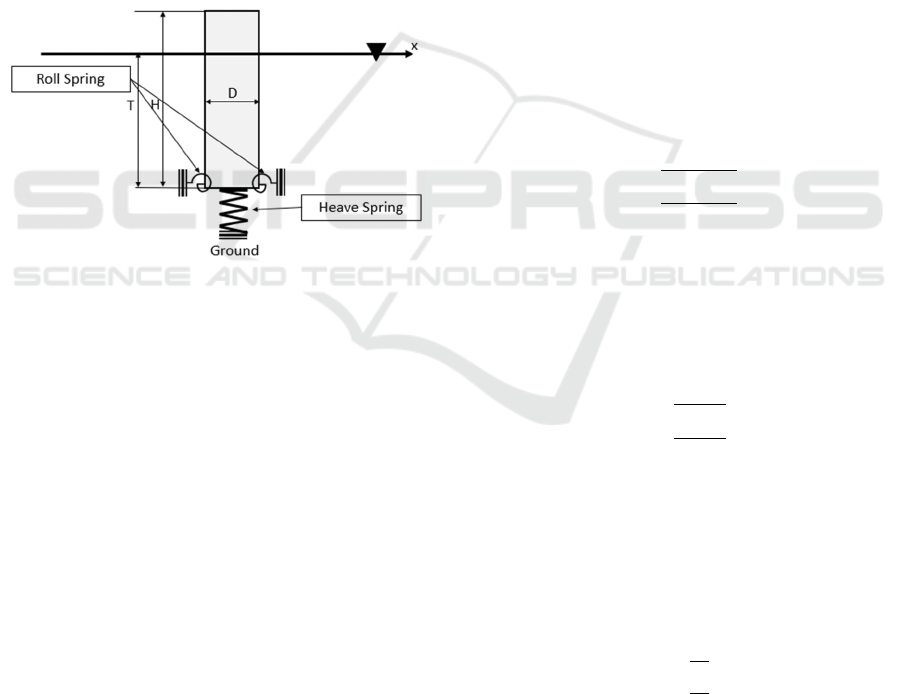
Figure 4: Equivalent Spring Arrangement.
4.1 Problem Setting
The proposed configurations above is treated as
structural system with precalculated heave and roll
spring as mentioned before at Chapter 2.2 and 2.3.
The heave and roll spring are placed at the bottom
of the cylinder, assumed that the support is located at
the bottom of the cylinder. This configuration is then
compared with traditionally ‘fixed’ boundary
condition at the bottom of the cylinder. In this paper,
we only compare the 1
st
order natural period of
heaving and rolling for:
1. Analytical hydrodynamic model
2. Rigid body-equivalent spring arrangement
model
3. Rigid body-traditional fixed boundary
condition arrangement model.
In analytical hydrodynamic model, the mass is
calculated as addition of water displacement and
added mass (Sarpkaya, 2010). Whereas the mass for
rigid body arrangement, both for spring and boundary
condition model, are modelled as its real mass,
instead of displacement and added mass. It is
important to calculate the mass with aforementioned
method, to check whether the ‘dry’ models, which
represented by rigid body model, can imitate the
natural frequency of ‘wet’ model, which represented
by hydrodynamics model.
Heave and roll spring stiffness are calculated as
mentioned in Chapter 2.2 and Chapter 2.3
respectively, and then placed at subsequent
arrangement as depicted in Figure 4.
4.2 Cylinder Diameter, Height and
Draught
The cylinder diameter (D) and height (T) are varied
with value 0.1≤D/T≤1.0. while the draught (T) is set
as 0.8H.
4.3 Natural Period
The natural period of heaving and rolling will be
calculated for the three configuration variations. The
natural period for ‘wet’ arrangement is calculated as
below for heaving motion:
T
=2π
m+m
k
(s)
(7)
Where:
m = real mass
maz = added mass for heaving motion
kz = heaving motion stiffness
And for rolling motion:
T
=2π
I+I
k
(s)
(8)
Where:
I = real inertial rolling motion
Iar = added inertial rolling motion
kr = rolling motion stiffness
The natural period for heaving motion for ‘dry’
arrangement is calculated as below:
T
=2π
m
k
(s)
(9)
Where:
m = real mass
kz = spring stiffness for heaving motion
ISOCEEN 2019 - The 7th International Seminar on Ocean and Coastal Engineering, Environmental and Natural Disaster Management
134

The natural period for rolling motion for ‘dry;
arrangement is calculated as below:
T
=2π
I
k
(s)
(10)
Where:
I = real inertial rolling motion
kr = rolling motion stiffness
5 RESULT AND DISCUSSION
5.1 Hydrostatic Stiffness
Hydrostatic stiffness is calculated and used as spring
stiffness and adequately inputted as spring stiffness at
each motion. The natural period of each motion is
then calculated and discussed as below.
5.2 Heaving Motion Natural Period
Figure 5 below shows the natural period
characteristics for each boundary condition
arrangement. First of all, the hydrodynamic natural
period is calculated for each D/H, represented by
triangle dots. The natural period increases with the
increase of the D/H. Then the rigid body motion is
calculated. Fixed boundary condition gives very low
natural period, which is near to zero, and considered
as unrealistic boundary condition due to the very wide
gap between the hydrodynamic and this boundary
condition.
Figure 5: Heaving Motion Natural Period for Each
Arrangement.
Equivalent spring motion natural period is
calculated and presented at Figure 5 by the cross dots.
The pattern of the equivalent spring natural period is
rather different with the hydrodynamic one, but still
in the same region. Maximum natural period for
equivalent spring is at D/H=0.1, where the value is
8.034 s. Where the maximum natural period for
hydrodynamics is D/H=1.0, the value is 7.683 s.
Adjustments is made to equivalent spring
stiffness. In order to imitate the hydrodynamics
properties, the spring stiffness is calculated by adding
hydrostatic stiffness with the multiplication of the
half ratio between diameter and height.
The value of the equivalent spring natural period
is then matched with the hydrodynamics natural
period, as explained by square dots at Figure 5. It
turns out that by multiplying the hydrostatic stiffness
with 0.5xD/T, the natural character of spring
arrangement is similar to the hydrodynamic
characteristic.
Similar natural period can be achieved by
arranging the spring as shown at Figure 4 for the
heaving motion of cylinder, by applying below
equation for the spring stiffness:
𝐾
=
2𝛾𝜋𝑟
2𝐻
(11)
Where:
K
ez
= heave equivalent spring stiffness
𝛾 = water specific weight
𝑟 = cylinder diameter
H = cylinder height
5.3 Rolling Motion Natural Period
Figure 6 below explains the natural period
characteristics for every boundary condition
arrangement. In the beginning, the hydrodynamic
natural period is analysed for each D/H, symbolized
by the triangular dots. Similar with heaving motion,
the natural period increases with the increase of the
D/H. The following result, which is rigid body
motion, is calculated. Again, identical with heaving
motion, fixed boundary condition gives very low
natural period, which is near to zero. This boundary
condition is considered as unrealistic due to the very
wide gap between the hydrodynamic and fixed
arrangement.
Equivalent spring motion natural period for
rolling motion is calculated and presented at Figure 6
by the cross dots. The pattern of the equivalent spring
natural period is similar with hydrodynamics motion
but resulting rather higher period.
Hydrostatic Stiffness as Displacement Boundary Condition of Floating Cylindrical Structural Analysis in Waves
135
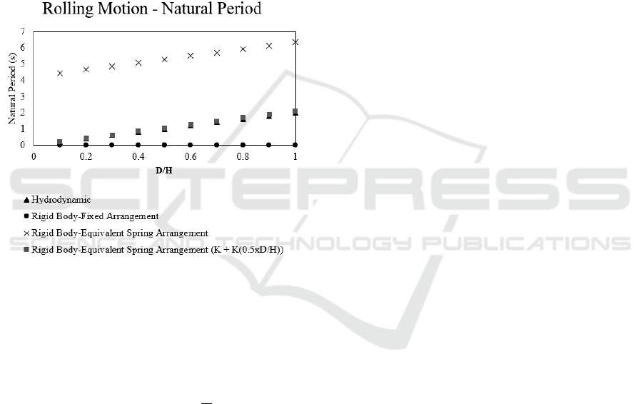
Maximum natural period for equivalent spring is
at D/H=1.0, where the value is 6.344 s. Where the
maximum natural period for hydrodynamics is
D/H=1.0, the value is 2.006 s. It turns out that the
difference between equivalent spring and
hydrodynamic natural characteristic can be
normalized by dividing the rolling natural period by
the ratio between the diameter and the height.
The value of the equivalent spring natural period
is then matched with the hydrodynamics natural
period, as explained by square dots at Figure 6. It
turns out that by dividing the rolling hydrostatic
stiffness by D/T, the natural character of spring
arrangement is similar to the hydrodynamic
characteristic for rolling motion.
Figure 6: Rolling Motion Natural Period for Each
Arrangement.
Similar natural period can be achieved by
arranging the spring as shown at Figure 4 for the
rolling motion of cylinder, by applying below
equation for the spring stiffness:
𝐾
=𝛾∇GM
(1 +
𝑟
𝐻
)
(12)
Where:
K
er
= roll equivalent spring stiffness
𝛾 = water specific gravity
∇ = water displacement
GM
= metacenter height of cylinder
r = cylinder radius
H = cylinder height
6 CONCLUSION
After going with the explained procedures to create
equivalent spring arrangement for heaving and rolling
motion, especially to singular cylinder, we can draw
conclusions as follow:
1. The value of the equivalent spring natural
period matches with the hydrodynamics
natural period by dividing the rolling
hydrostatic stiffness by D/T the hydrodynamic
characteristic for rolling motion.
2. For heaving motion, in order to imitate the
hydrodynamics properties, the spring stiffness
is calculated by adding hydrostatic stiffness
with the multiplication of the half ratio
between diameter and height.
7 FURTHER WORKS
The future works should refine the hydrostatic
stiffness modelling by considering the ground spring
height.
Further works also should develop more
hydrostatic equivalent spring stiffness for more
complex structure, e.g.: boxes, multiple cylinders,
and ship shaped structures.
ACKNOWLEDGEMENT
This work is part of the research funded by DRPM
(Direktorat Riset dan Pengabdian Masyarakat) Insitut
Teknologi Sepuluh Nopember Surabaya, Indonesia.
Contract number 1233/PKS/ITS/2019. Author’s
gratitude to the funding department is acknowledged.
REFERENCES
ABS, 2014. Rules for Building and Classing Floating
Production Installation. Houston: American Bureau of
Shipping.
Agamloh, E., Wallace, A. & Jouanne, A., 2008. Application
of fluid–structure interaction simulation of an ocean
wave energy extraction device. Renewable Energy,
33(4), pp. 748-757.
Bhattacharya, R., 1978. Dynamics of Marine Vehicle. New
York: John Wiley & Sons.
Chen, L. et al., 2014. Numerical investigation of wave–
structure interaction using OpenFOAM. Ocean
Engineering, Volume 88, pp. 91-109.
ISOCEEN 2019 - The 7th International Seminar on Ocean and Coastal Engineering, Environmental and Natural Disaster Management
136

Datta, T., 2010. Seismic Analysis of Structures. Singapore:
John Wiley & Sons (Asia).
Gazetas, G., 1991. Foundation Vibration, Chapter 15. In:
Foundation Engineering Handbook. New York: Van
Nostrand Reinhold, pp. 553-593.
Huang, L. & Riggs, H., 2000. The hydrostatic stiffness of
flexible floating structures for linear hydroelasticity.
Marine Structures, 13(2), pp. 91-106.
Ma, S. & Mahfuz, H., 2012. Finite element simulation of
composite ship structures with fluid structure
interaction. Ocean Engineering, Volume 52, pp. 52-59.
Molland, A., ed., 2008. The Maritime Engineering
Reference Book: A Guide to Ship Design,
Constructuion and Operation. Oxford: Butterworth-
Heinemann.
Okumoto, Y., Takeda, Y., Mano, M. & Okada, T., 2009.
Design of Ship Hull Structures: A Practical Guide for
Engineers. Berlin: Springer-Verlag Berlin Heidelberg.
Patel, M. & Witz, J., 1991. Compliant Offshore Structures.
Oxford: Butterworth-Heinemann Ltd.
Raja, R., 2012. Coupled fluid structure interaction analysis
on a cylinder exposed to ocean wave loading (Master's
Thesis). Gothenburg: Chalmers University of
Technology.
Sarpkaya, T., 2010. Wave Forces on Offshore Structures.
Cambridge: Cambridge University Press.
Senjanović, I., Hadžić, N. & i Vladimir, N., 2011. Restoring
Stiffness in the Hydroelastic Analysis of Marine
Structures.. Brodogradnja, 62 (3), pp. 265-279.
Hydrostatic Stiffness as Displacement Boundary Condition of Floating Cylindrical Structural Analysis in Waves
137
