
Control Circuit based Microcontroller Implementing a New
Sinusoidal Pulse with Modulation Technique for Solar Inverter
Abdennabi Brahmi
1
, Abdelouahed Abounada
2
, Zakaria Massaq
2
and Aumeur El Amrani
1
1
Faculty of Sciences and Techniques, Statistical Physics and Systems Modeling Laboratory, Errachidia, Morocco
2
Faculty of Sciences and Techniques, Automatics and Energy Conversion Laboratory, Beni-Mellal, Morocco
Keywords: Sinusoidal Pulse Width Modulation SPWM, DC/AC Inverter, Discretized Sinusoidal Signal, Look Up Table,
PIC16F876 Microcontroller.
Abstract: This paper presents a new technique to generate a digital Sinusoidal Pulse Width Modulation (SPWM) control
using PIC16F876 microcontroller. This technique is mainly used to control the DC/AC inverter output voltage
in many applications such as photovoltaic pumping system and motor drive. It reduces significantly low
harmonic components as well as distortion factor. The principle of this method is to transform the sampled
dc-biased sine wave signal to a repeating pulses train. The widths of these pulses vary sinusoidally and thus
as a digital SPWM. The different amplitude modulations index started from 0.5 until 1.3 (over modulation)
with 1 kHz switching frequency was implemented and tested. The literature review of the existing digital
SPWM techniques is presented firstly. Subsequently the proposed SPWM approach is briefly detailed.
Finally, experimental results are presented to demonstrate the validity of this SPWM method and the good
functionality of the realized control unit.
1 INTRODUCTION
Pulse width modulation PWM is widely used in
power electronics to digitize the power so that a
sequence of alternating voltage pulses can be
generated by the on and off of the inverter power
switches (Lucien, 2008), (Selvabharathi, Kamatchi,
Sathish, 2018.). Inverter is defined as a converter that
is used to change a DC input voltage to an AC output
voltage of desired magnitude and frequency
(Gavaskar, Maheswari, Adi, 2017), (Tarchanidis,
Lygouras, Botsaris, 2013). The output voltage of an
ideal inverter is the sinusoidal waveform which could
be fixed or variable at a fixed or variable frequency.
For the inverter, the harmonics spectrum exist at all
odd number of harmonics. The low-pass filter design
at the output of the inverter also can be quite difficult
(Gavaskar, Maheswari, Adi, 2017).
Sinusoidal PWM SPWM is as the alternative due
to the fewer harmonics introduced and it is widely
used method for major AC appliances. The analogue
method compares triangle wave which is used as
carrier with the sinusoidal wave as the reference
signal, whose frequency is the desired output
frequency. The fundamental component is useful for
any alternating current application. The digital
SPWM version is inspired from analogue SPWM
(Lucien, 2008).
With Field Programmable Gate Array FPG device
(Selvabharathi, Kamatchi, Sathish, 2018), Digital
Signal Processor DSP (Gavaskar, Maheswari, Adi,
2017), both the sine wave and triangle wave are
generated by a special intern controller. An internal
comparator is used to compare these signals. The
crossover points are used to determine the switching
instants such that if the sine wave is greater than
triangle wave then the output is high otherwise output
is low, thus a SPWM is created. These devices have
very high performance and density, more flexible but
present high cost.
With microcontrollers, there are three most
methods used to generate the SPWM. The first one
uses generally a counter (Abdel, Thomas, Ramadan,
2017). These counters have the task to create the sine
wave using a look up table of a pre-calculated sine
values. The triangle wave also is created with another
counter along with a control bit showing the slope
(positive – up, negative-down).
These two tasks are executed by the interrupt
service routine and are running in parallel with the
Brahmi, A., Abounada, A., Massaq, Z. and El Amrani, A.
Control Circuit based Microcontroller Implementing a New Sinusoidal Pulse with Modulation Technique for Solar Inverter.
DOI: 10.5220/0009775102710276
In Proceedings of the 1st International Conference of Computer Science and Renewable Energies (ICCSRE 2018), pages 271-276
ISBN: 978-989-758-431-2
Copyright
c
2020 by SCITEPRESS – Science and Technology Publications, Lda. All rights reserved
271

main program routine. The computation time
consumed by the interrupt service routine is
negligible. The second task consists of an endless
loop that has the task to continuously compare the
current triangle and sine values. The comparison
result will be responsible to create the SPWM trigger
signals.
The second technique uses the simple software
modulation (multiplication) on microcontroller
(Tarchanidis, Lygouras, Botsaris, 2013). A sine wave
(with unity magnitude and low frequency) is
multiplied with the impulse train (with high
frequency and unity magnitude) in order to create a
train of SPWM pulses. Theses SPWM triggers can be
generated in such a manner that starting position of
pulse should be same as that of impulse and duty
cycle of the pulse must be equal to the product of unit
impulse and value of sine wave at that instant.
The third approach (Bilal, 2018) uses the output
compare modules in the DSPIC33FJ microcontroller.
This microcontroller contains two output compare
modules. Both these Outputs are used to generate
SPWM using two look up tables; sine look up table
and triangular look up table. Each module use two
sixteen bit timers that is Timer 2 and Timer 3. OCM
register compares the set value of sine wave with
triangular values in each period time of the triangular
and write the comparison results to OCxR and OCxRS
registers of the output compare modules.
When both values become equal to each other,
state of output pin changes. It happens only once in
one period of PWM.
The simplicity without increasing resources,
programmability, the medium rapidity and the low
cost make the microcontroller device the most
favourable choice for prototyping digital control
circuit for our solar pumping inverter (Pattnaik,
Dash, Mukherjee, 2009), (Salam, 2001).
The new method we proposed in this work
consists on storing the different pulse widths (i.e. duty
cycles) of the desired SPWM signal in a look up table.
These duty cycles are obtained beforehand from
discrete values of a continuously dc-biased sinusoidal
function.
These results are stored in memory as a pulse
width table covering the entire period of the output
signal of the inverter.
This method offers several advantages in terms of
resolution and gain of the generated SPWM signal,
which remain constant regardless of the PWM output
frequency even at high frequency. The main feature
of this approach is the simplicity of the hardware;
only a very simple microcontroller with its associated
PWM output modules is required without using a test
of comparison. This results in a simple, low cost and
reliable control for a solar pumping system. The full
detail of this approach is given in the following
section.
2 PROPOSED DIGITAL SPWM
TECHNIQUE
2.1 Theory
The pulse widths (i.e. duty cycles) are constructed
from discrete values of a sinusoidal function (Ismail,
Taib, Isa, Daut, Mohd Saad, Fauzy, 2007). To
generate the repeating SPWM pulse train in complete
frequency F
ref
cycle of the sine reference wave cycle,
we first need a table whose values represent the
magnitude of this sine wave using the following
formula (Gavaskar, Maheswari, Adi, 2017):
2
sin
i
SA
i
n
For i = 0…n-1
(1)
Since the PWM registers of the 16F876 accept
only positive values (PIC16F87X microcontrollers,
2001), (Ismail, Taib, Mohd Saad, Isa, Daut, 2006), we
can transform modulated sine wave in a dc-biased
sine wave to avoid the negative values. With this
transformation, the dc-biased sine wave samples S
dc
can be written as:
B
n
i
AS
dci
)
2
sin(
For i = 0…n-
1
(2)
Where i is the sample number, and n is the number
of samples per complete F
ref
sine wave cycle. This
number is the equivalent parameter of the frequency
modulation index in the analogue SPWM control
(Ismail, Taib, Daut, Mohd Saad, Fauzy, 2007). It
depends on the desired switching frequency F
s
of the
SPWM patterns and the F
ref
sine wave cycle as:
ref
s
F
F
n
(3)
A is the amplitude of the considered sine wave,
this parameter depends with the desired amplitude
modulation index m
a
like in
analogue SPWM control
(Ismail, Taib, Mohd Saad, Isa, Daut, 2006.) and with
ICCSRE 2018 - International Conference of Computer Science and Renewable Energies
272

PR2 register’s value (PIC16F87X microcontrollers,
2001):
2
2PR
mA
a
(4)
PR2: period register of the PIC16F876.
B: the dc-biased value it depends with the value
that will be specified in PR2 register, this value is the
half of PR2 value that is expressed as follows:
2
2
PR
B
(5)
A table of n values (sample points) of a complete
F
ref
sine wave cycle with an angle resolution (2*π/n)
is obtained using equation (2). These samples values
represent the pulse width values or exactly the duty
cycles that can be sent periodically based Timer 2
interrupt mechanism to the PWM modules to generate
the desired SPWM switching signal. The period T
s
of
the SPWM signal is set by writing to the PR2 register
(PIC16F87X microcontrollers, 2001) using:
TpTPRTs
osc
4)12(
(6)
Where T
osc
is the timer oscillator and T
p
is the
timer prescaler value.
The duty cycles d
wi
are specified by writing S
dci
values to the CCPRxL registers (x=1, 2) using only
eight MSBs (PIC16F87X microcontrollers, 2001):
TpTCCPRxLd
oscw
)(
(7)
Based on equation (7), the PWM module
transforms the S
dci
values to a duty cycles values d
wi
.
When the CCP modules are used in the PWM
module (PIC16F87X microcontrollers, 2001), the
timer 2 register is used as the PWM time base. It
works by incrementing a counter at a user set
frequency F
s
, and when the value of this counter
equals the period programmed in PR2 register, an
interrupt is generated at each T
s
period.
The main idea to generating the repetitive pulse
train that varies sinusoidally is the use of the PWM
module based its Timer 2 interrupt, so in each
interrupt; the duty cycles d
wi
values is read from the
sampled sine value in look up table and then sent to
CCPRxL registers. This approach is repeated for all
the n values in the created look up table in order to
generate SPWM patterns for complete T
ref
period.
To generate the SPWM in the sine wave cycle
(F
ref
=50Hz), we noticed that only have to save a
quarter value of the calculate values d
wi
in a look up
table array. This quarter allows creating the first
SPWM quarter using a p pointer and a i counter.
The remained three SPWM quarters were
deduced from this first SPWM1 quarter. Based only
this created look up table, the complementary
SPWM2 of the SPWM1 can be also deduced using
the same p pointer with a similar manner.
2.2 Numerical Application
For this implementation, the values of used
parameters are given in table 1 bellow.
Table 1: The values of used parameters.
F
s
F
ref
PR2 n B
1 kHz 50 Hz 104 60 52
Using the equation (6), to obtain F
s
equal to 1
kHz, we might use the timer prescaler with the value
16, and write 104 values to PR2 register. Based on
equation (3), at this frequency, the number n of pulses
per complete cycle of a reference frequency F
ref
of 50
Hz is n= 60.
From equation (4), the constant A depends on the
desired modulation index m
a
and the PR2 value.
Knowing that CCPR1L and CCPR2L are an 8-bit
registers, from equation (5), the constant B is equals
to 52, and i=0…59. The exact number that need to be
stored in look up table and thus be loaded into the
pulse width register PWM must therefore equal to S
dci
values obtained using equation(2) multiplied by the
amplitude modulation index m
a
.
The amplitude of the inverter output voltage is
controlled by m
a
. This is significant for using
photovoltaic panels to supply this inverter, because
the photovoltaic source produce a variable output
voltage according to the variations of the climatic
conditions. Thus producing constant amplitude
output voltage. If m
a
is greater than 1 (over
modulation), the amplitude of the output voltage
increase with m
a
, but not linearly. In order to work in
region, the m
a
must be lower than 1 to keep a linear
relationship between m
a
and the output voltage
amplitude in ordrer to control the solar inverter’s
output voltage.
Matlab Simulink software was used to generate
60 pulse widths train for i=0…59. And then we store
only its 15 first values in look up table array. This
trick allows optimizing the used of the
microcontroller memory program.
Control Circuit based Microcontroller Implementing a New Sinusoidal Pulse with Modulation Technique for Solar Inverter
273
3 SYSTEM DESIGN
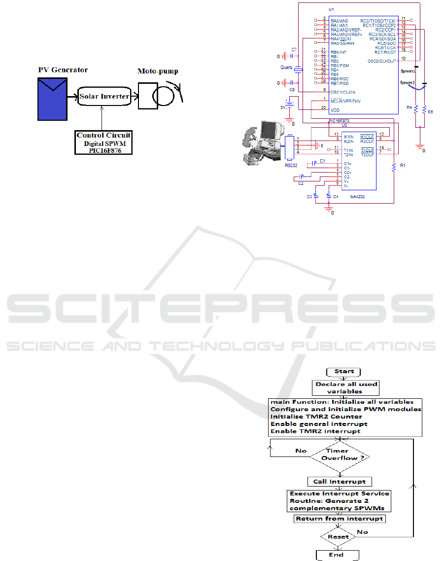
The basic schematic diagram of the solar pumping
inverter to be designed and realized in our laboratory
is shown in the figure 1 below:
Figure 1: Control circuit of solar pumping inverter.
It consists of two parts: the power circuit and the
control circuit. In this work, we focused on the control
circuit. This last circuit is formed by many blocs; its
heart is a PIC16F876 that generate two
complementary SPWMs.
This section involves two parts: the Hardware and
the Software. Indeed, the Software development
involves the application of C language using CC5X
compiler integrated with MPLAB Software based
Bootloader technique (Beningo, 2015).
3.1 Hardware Design
The proposed technique deals with the use of a
PIC16F876 microcontroller for the implementation.
The use of this microcontroller brings more
reliable and resilient to change in software than
analogue devices. The advantage of this new method
is the use of a little calculation, and a discretized dc-
biased sinusoidal signal look up table values is
needed.
The schematic circuit for programming the
microcontroller was drawn as shown in figure 2.
There are two integrated circuits in this schematic
circuit. One is the PIC microcontroller, which does
almost everything. The other is a MAX232 chip
which converts TTL level (5V) signals to RS232
levels (12V) so that you can talk between a personal
computer's serial port and a TTL level UART device.
In order to ensure the microcontroller function, as
supply of 5 volts has to be provided to V
DD
pin of the
PIC chip.
Figure 2: Schematic circuit for PIC programming using
Bootloader technique.
Therefore, High Speed crystal (HS) of 4 MHz is
chosen. The PWM pins were used to generate two
complementary 5 volts level SPWM patterns.
3.2 Software Design
The flowchart (figure 3) of the SWPM patterns
generation is composed into two parts: main function
and interrupt service routine (ISR) function.
Figure 3: SPWMs patterns flowchart generation.
ICCSRE 2018 - International Conference of Computer Science and Renewable Energies
274
On reset, all hardware setting from the
microcontroller configuration is loaded into the
device and main function is executed firstly.
The figure 4 shows an infinite loop is entered,
when Timer 2 reaches the PR2 value (TMR2
overflow), the interrupt service routine (ISR) is
executed.
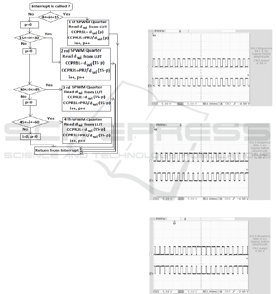
Figure 4: Interrupt Service Routine flowchart.
In this routine, the duty cycles values in look up
table are read and sent to CCPR1L and CCPR2L
registers every time when the TMR2 overflow. This
figure describes all the operations taking place in this
interrupt based p pointer and i counter.
This p pointer is incremented, to point the next
duty cycle value in the table, and the i counter is also
incremented in order to indicate the corresponding
SPWM quarter. In each T
s
, a new values are read and
sent to CCPR1L and CCPR2L registers. In this
interrupt mechanism, we have four tests to determine
the corresponding SPWM quarter.
The duty cycles values are read from the table and
then sent to the CCPRxL registers (x=1, 2) to generate
two complementary SPWM signals. The loop can be
terminated by resetting the reset switch of the
hardware bar. These SPWM signals will be used to
turn on and off the inverter’s power transistors in
order to create a sine wave output voltage with
reference frequency F
ref
.
4 EXPERIMENT RESULTS
The experimental setup is tested for different
amplitude modulation index m
a
for F
ref
=50Hz and
F
s
=1kHz. The selected results have been chosen to
illustrate some of main futures of microcontroller
SPWM control, which have been presented in this
paper. The control circuit is expected to output two
pulses with varying duty cycles that are 180° out of
phase with 1kHz switching frequency that depicted in
figure 5 to figure 8 below.
Figure 5: Complementary SPWMs for m
a
= 0.5.
Figure 6: Complementary SPWMs for m
a
= 0.7.
Figure 7: Complementary SPWMs for m
a
= 0.8.
Control Circuit based Microcontroller Implementing a New Sinusoidal Pulse with Modulation Technique for Solar Inverter
275
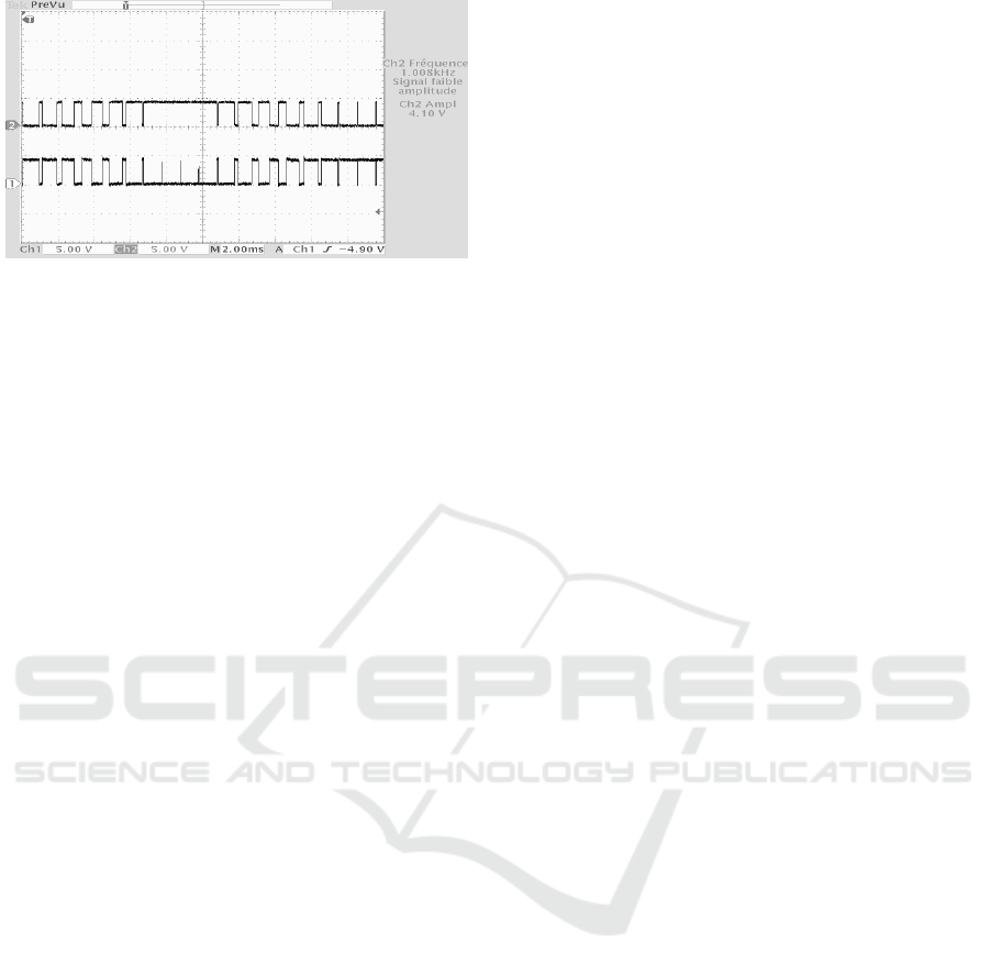
Figure 8: Complementary SPWMs for m
a
=1.3 (over
modulation).
These figures show the switching signal for
difference amplitude modulation index m
a
(m
a
=0.5;
0.7; 0.8 and m
a
=1.3).
These results illustrate the amplitude modulation
index effect in the size of the pulses width. When the
m
a
is lower, the size of pulse is reduced and vice
versa. This allows implementing a very simple
adaptive voltage control for an inverter.
The results are very close to the expected values,
which certify that the SPWM control circuit is
functioning appropriately. For the reasons of safety
and to ensure better switching mechanism in the
power circuit, an opto-coupler and driver must be
inserted between the microcontroller output and the
power switches of the solar inverter.
5 CONCLUSION
The main task in this work was to develop a new
SPWM technique for the inverter control circuit for a
solar pumping system using look up table technique.
This proposed approach remains very simple and
allows eliminating the use of more electronic
components, thus a low price and minimum
occupation in the PCB board concept.
The investigated controller approach is able to
produce two complementary SPWMs with desired
switching frequency and amplitude modulation
index. The efficiency of this method is that the output
pulse width can be easily varied by changing PWM
register’s value based m
a
index and thus a simple
adaptive control system can be implemented.
Also, this technique may be extended for a three-
phase solar inverter for pumping system.
The obtained experimental results were presented
and they were found to agree well with other
established work. In addition, we are working on the
practical realization of a new and compact solar Boost
pumping inverter.
REFERENCES
Lucien, N., Leary, M., 2008. Digital SPWM synthesis for
the design of single phase inverters, International
Journal of Electronics, Taylor & Francis Vol. 95, No. 5,
pp: 489–503.
Selvabharathi, P., Kamatchi K., V., Sathish, K., S., 2018.
SPWM based speed control of induction motor using
FPGA controller, International Journal of Pure and
Applied Mathematics; Vol. 119, No. 18, pp:2395-2403.
Gavaskar, R., B., Maheswari, L., Adi, G., K., 2017.
Performance improvement of single phase inverter
using SPWM. In ICMAEM’07, Conference Series
Materials Science and Engineering. India.
Tarchanidis, K., N., Lygouras, J., N., Botsaris, P., 2013.
Voltage stabilizer based on SPWM technique using
microcontroller, Journal of Engineering Science and
Technology Review, Vol. 6, No. 1, pp:38-43.
Abdel, S., S., Thomas, J., Ramadan M., 2017. Design and
Implementation of a Single Phase SPWM Inverter
Based Microcontroller for Wind Energy Conversion
Systems, International Journal of Systems Applications,
Engineering & Development, Vol. 11, pp: 291-296.
Bilal, 2018. DsPIC33F microcontroller based pure sine
wave inverter, microcontroller project,
microcontrollersLab.com.
Pattnaik, B., S., Dash, D., K., Mukherjee, J., 2009.
Implementation of PWM based firing scheme for
multilevel inverter using microcontroller, Department.
Electronic Engineering National Institue of
Technology, Rourkela-769008, Orissa.
Salam, Z., K., 2001. Generation of Pulse Width Modulation
PWM signals for three-phase inverter using a single
chip microcontroller, Jurnal Teknologi, 34(D),
Universiti Teknologi Malaysia, pp.1-12.
Ismail, B., Taib, S., Isa, M., Daut, I., Mohd Saad A., R.,
Fauzy, F., 2007. Microcontroller implementation of
single phase inverter switching strategies, In CIM’07,
International Conference On Control, Instrumentation
and Mechatronics Engineering. Johor Bahru, Malaysia,
pp: 104-107.
PIC16F87X microcontrollers, 2001. datasheet, DS30292C,
Microchip Technology, available:
www.microchip.com.
Ismail, B., Taib, S., Mohd Saad, A., R., Isa, M., Daut, I.,
2006. Development of control circuit for single phase
inverter using Atmel microcontroller. In ICMMS’06,
International Conference of Man-Machine System.
Langkawi.
Beningo, J., 2015. Bootloader Design for Microcontrollers
in Embedded Systems.
ICCSRE 2018 - International Conference of Computer Science and Renewable Energies
276
