
Heat Recovery Technology Applications for the Desulfurization
Process of Phosphgypsum
M. Alla
a*
, M. L. El Hafyani
a
, S. Zouggar
a
, E. K. Gharibi
b
a
Laboratory of Electrical Engineering and Maintenance, Higher School of Technology,
University Mohammed First Oujda, Morocco
b
Laboratory of Solid Minerals and Analytical Chemistry, Faculty of Sciences,
Mohammed First University, Oujda, Morocco
Keywords: ORC, Phosphogypsum, desulfurization, SO2, waste heat, Enthalpy H.
Abstract: The Organic Rankine Cycle (ORC) is a very important technology for converting the deadly heat from
which it is desired to produce mechanical power at low or medium temperatures to produce electricity.
This paper presents existing applications and of desulfurization of phosphogypsum (PG). Provided the
interest to recover waste heat rejected by thermal devices and industrial processes continue to grow, and
favorable legislative conditions are adopted, waste heat recovery organic Rankine cycle systems in the near
future will experience a rapid growth at very low temperature. In this study the energy released by the
phosphogypsum desulfurization system on the ORC machine will be applied to produce the electricity.
1 INTRODUCTION
As the human population grows, it becomes
increasingly dependent on energy; the increasing
consumption of fossil fuels has led to more and more
environmental problems such as global warming,
ozone depletion and atmospheric pollution.
Furthermore, along with the fast development of
industry, energy shortages and blackouts have
appeared more and more frequently all over the
world. Due to all these reasons, utilizing low-grade
waste heat for energy production has attracted more
and more attention for its potential in reducing the
fossil fuel consumption. Thus, an excess of heat is
generated during many stages of the production and
processing of an energy intensive system. Thus, the
development of cogeneration capable of recovering
and converting and fatal heat into electrical energy,
this technology is one of the main pathways to a
high-efficiency, low-temperature energy future.
These technologies have been known for the
production of electricity, applied in many forms
ranging from domestic applications to industrial
applications in order to combine heat and electricity,
including various Stirling, thermoacoustic and
thermofluidic heat engines.
For a very important efficiency, it is necessary
that the heat occurs at the lowest possible
temperature. This is best achieved by generating
energy in combined cycle mode. Commercial
combined cycles generally use a gas turbine. These
heavy-duty gas turbines with higher output
temperatures, and also are technically and
economically viable for combined cycle
applications. There are five main focus points when
optimizing an ORC: the heat source type, the
selection of the working fluid, the hardware
components, the control strategy and the component
layout and sizing. The heat source can be waste heat,
solar energy, geothermal heat or biomass
combustion.
1.1 Organic Rankine Cycle Applications
1.1.1 Binary Geothermal Power Plants
Geothermal energy refers to both the science that
studies the internal thermal phenomena of the
terrestrial globe and the technology that aims to
exploit it. By extension, geothermal energy also
36
Alla, M., El Hafyani, M., Zouggar, S. and Gharibi, E.
Heat Recovery Technology Applications for the Desulfurization Process of Phosphgypsum.
DOI: 10.5220/0009774800360041
In Proceedings of the 1st International Conference of Computer Science and Renewable Energies (ICCSRE 2018), pages 36-41
ISBN: 978-989-758-431-2
Copyright
c
2020 by SCITEPRESS – Science and Technology Publications, Lda. All rights reserved
sometimes refers to geothermal energy from the
energy of the Earth that is converted into heat.
To capture geothermal energy, a fluid is
circulated in the depths of the Earth. This fluid can
be that of a natural captive hot water sheet, or water
injected under pressure to fracture a hot and
impervious rock. In both cases, the fluid warms up
and goes back loaded with calories (thermal energy).
These calories are used directly or partially
converted into electricity, allowing some locations to
be more suitable for geothermal applications than
others represent by figure 1:
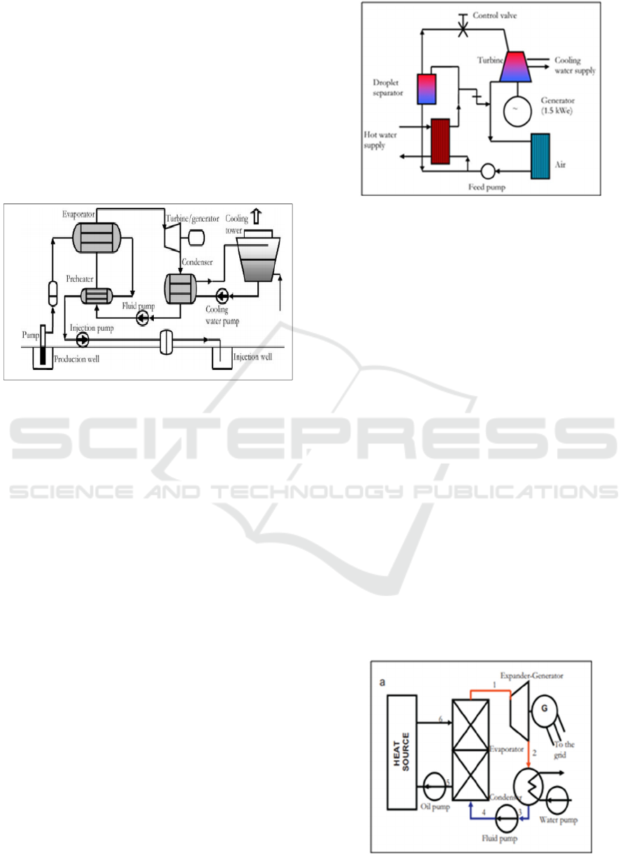
Figure 1: Flow diagram for a binary geothermal power
plant.
1.1.2 Solar Thermal Power Systems
Several factors increase the market potential of
power plants: the need for distributed power systems
in remote areas, the need for sustainable power for
the economic growth of developing countries and
also for producing clean electricity with the help of
renewable energy sources. Rankine cycle modular
organic solar power plants operate on the same
principle as conventional systems but use an organic
fluid instead of steam. The advantages of these
systems are as follows:
Low temperature operation (<300 ° C): low
temperature solar collectors and ORC modules
that can work well in regions of low solar
radiation intensity, such as sub-Saharan regions
African.
Modularity: it is possible to build large solar
ORC plants of several MW of power by
combining on the same site a large number of
ORC modules. Compressed air diaphragm pump
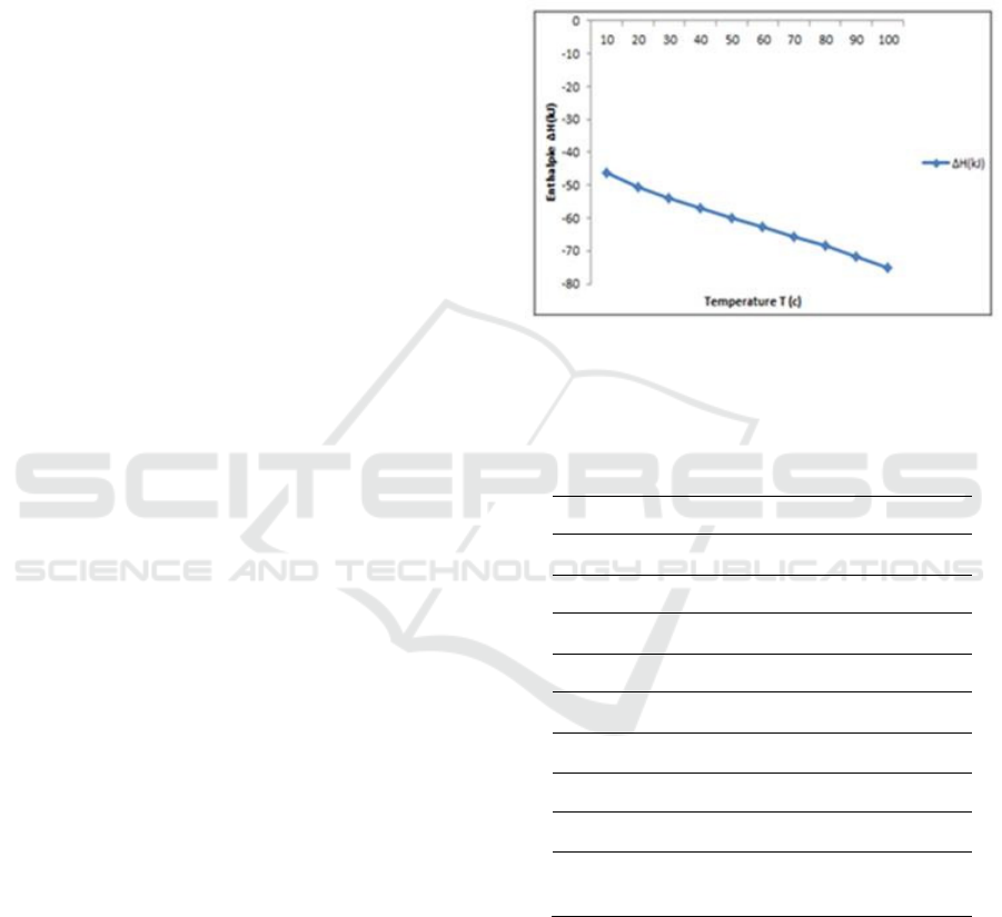
and a radial flow.
Turbine (65.000 rpm) coupled to a high speed
alternator (Fig. 2).
Figure 2: A micro-organic Rankine power system
1.2 Organic Rankine Cycles (ORCs) in
Waste Heat Recovery Application
Waste heat is the unused heat generated during a
combustion process or any other chemical
reaction/thermal process and, then directly
exhausted to the environment. Industrial energy
intensive processes as well as thermal engines and
mechanical equipment’s produce large amounts of
such waste heat . Exhausts discharged do not only
contain high exergy value but also large quantities of
pollutants: carbon dioxide (CO
2
), nitrogen oxides
(NO) and surlphur oxides (SO
x
) responsible of high
level concentration of atmospheric greenhouse gases
and of the global warming. Some developed
countries in view of cutting off their harmful gas
emissions while decreasing their energy imports in
the meantime have evaluated their waste heat
recovery potential. A study conducted within the
eight largest manufacturing sectors in Canada
showed up to 70% energy input lost . According to a
report published by the US Department of Energy
(DOE) in 2008, the industrial sector alone accounts
for about one third of the total energy consumed in
the country and contributes in the same proportion to
greenhouse gas emissions.
Figure 3: Flow diagram for a waste heat
Heat Recovery Technology Applications for the Desulfurization Process of Phosphgypsum
37
2 DESULFURIZATION PROCESS
OF PHOSPHOGYPSUM
The development of the fertilizer industry leads to
the production of more and more phosphoric acid
(more than 93% is CaSO
4
.2H
2
O) by treating natural
phosphates with sulfuric acid, this industry releases
significant amounts of phosphogypsum (PG), Solid
phosphogypsum waste often contains substances that
are directly hazardous or may become hazardous
during storage. Large quantities are produced world-
wide and it is estimated that by the year 2000 up to
280 million tones will be produced annually (in
Morocco 8 million tons per year).
2.1 Experimental Procedure
Phosphogypsum (PG) is placed in a reaction
chamber, attacked with concentrated hydrochloric
acid at boiling temperature. Varying amounts of
metallic iron are added to the phosphogypsum prior
to the etching step. After having dissolved almost all
the solid, we filtered cold and kept both the
insoluble residue and the solution. The gas released
from the reaction chamber is bubbled through
solutions that retain the Sulphur dioxide (SO
2
) gas.
The phosphogypsum reacts in the hydrochloric
medium in the presence of iron and the product
formed is SO
2
gas can be presented by the following
reaction [8]:
CaSO
4
. 2H
2
O + 4HCl + Fe Ca
2+
+ 4Cl
-
+ Fe
+2
+
4H
2
O + SO
2
(g) (Reaction 1)
Amounts of 400 g of the raw PG are placed in a
reaction chamber, attacked with concentrated
hydrochloric acid under boiling temperature.
Variable amounts of the metallic iron are added to
the PG before the attack step. After dissolving nearly
all of solid, we filtered out cold and we kept both the
insoluble residue and solution. After, the attack
solution was analyzed and the escaped gas was
recovered and assayed. The analytical techniques
used are X-ray diffraction 6000 SHIMADZU to
characterize structure of initial
and solid residues after attack. The PG
decomposition with a strong HCl acid (varying acid
/ solid / metal ratios) at the boiling point is carried
out in a reaction chamber partially insulated from
atmospheric pressure. The gas released from the
reaction chamber is bubbled through solutions that
keep SO
2
in the form of gas. SO2 gas which is
released from the reaction chamber by bubbling into
a solution of H
2
O
2
. Titration of excess H
2
O
2
by a
strong oxidant, KMnO
4
, indirectly gives the amount
of SO
2
released.
The table 1 gives the values of the
thermodynamic quantities calculated in function of
the temperature.
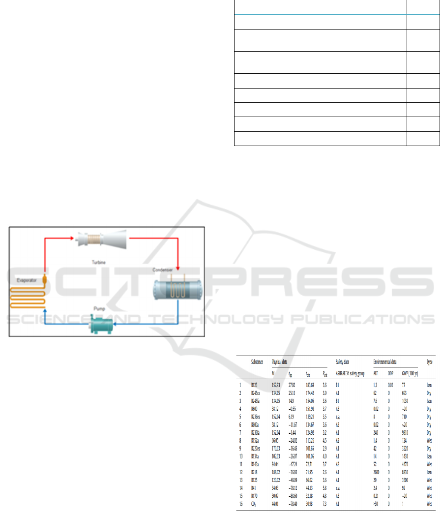
The evolution of the enthalpy in function of the
temperature is given by the figure 4.
Figure 4: Enthalpies of reaction 1 calculated at different
temperatures
Table 1: Thermodynamic parameters of Reaction 1
T
(°C )
∆H
(kJ)
∆S
(J/K)
∆G
(kJ)
Lo
g
K
10 -46.225 166.395 -93.340 17.221
20 -50.587 151.244 -94.924 16.915
30 -54.041 139.654 -96.377 16.608
40 -57.069 129.822 -97.723 16.302
50 -59.944 120.786 -98.976 16.000
60 -62.752 112.228 -100.140 15.702
70 -65.579 103.867 -101.221 15.409
80 -68.546 95.347 -102.217 15.120
90 -71.708 86.519 -103.127 14.835
100 -75.129 77.227 -103.946 14.552
As shown as in Fig. 1 Enthalpy increases linearly
as a function of temperature, which implies that our
system of desulfurization of phosphogypsum is
exothermic, which requires the valorization of this
fatal thermal energy to protect the environment.
2.2 Mathematical Model
Energy and energy analyzes based on the first and
second laws of thermodynamics are evaluated for
ICCSRE 2018 - International Conference of Computer Science and Renewable Energies
38
different organic working fluids under different
working conditions.
For the sake of simplicity, the internal
irreversibility and the pressure drops in the
evaporator, the estimation of the thermodynamic
properties of the condenser and the pipes will be
neglected. And each component is considered a
constant and stable flow system. Introduce the
equations to perform the thermodynamic
comparative analysis.
Evaporator/Vapor Generator
∆S = ∆Q/T (1)
Q = m
.
(h
in
t – h
out
) (2)
Turbine
W = m
r
.
(h
int
–h
g
) (3)
V
int
= m
r
*v
int
(4)
V
out
= m
r
*v
out
(5)
Figure 5: Schematic diagram of an ORC system
2.3 Choice of the Working Fluids
It is clear that, in order to calculate the ORC system
performance, a relevant number of parameters are to
be set. The inlet temperature of the heat source and
sink, the pinch temperature difference and flow rate
of the heat source were assumed in Table 2. The
flow rate of the heat sink is calculated to fulfill the
cooling needs. Saturated vapor was assumed at the
turbine inlet in subcritical ORC system. The basic
assumptions for the plant components are also listed
in Table2.
Table 2: Assumptions for heat source and sink and power
plant components.
The temperature of the thermal water, °C
90
The temperature of the cooling water, °C
20
The pinch temperature difference in both heat
exchangers, °C
5
The mass flow rate of the geothermal water,
kg/s
1
Isentropic efficiencies for the turbine
0.9
Isentropic efficiencies for the pump
0.75
Generator efficiency
0.96
Water pump efficiency
0.75
Turbine outlet quality
0.8
According to the temperature-entropy diagrams,
fluids show three different types of slope on their
saturation vapor curves and can be categorized into
three groups: (1) dry fluids have positive slope, (2)
wet fluids have negative slope, (3) isentropic fluids
have nearly vertical saturated vapor curves. The wet
fluids are generally not adequate for subcritical ORC
systems because they become saturated once they go
through a large enthalpy drop after producing power
in the turbine, and the condensate of the fluids
imposes a threat of damage to the turbine. The dry
and isentropic fluids can prevent the above
disadvantage [10]. Table 3 lists some properties of
the working fluids considered here.
Table 3: Basic thermodynamic and environmental
properties of the selected fluids [10]
Heat Recovery Technology Applications for the Desulfurization Process of Phosphgypsum
39
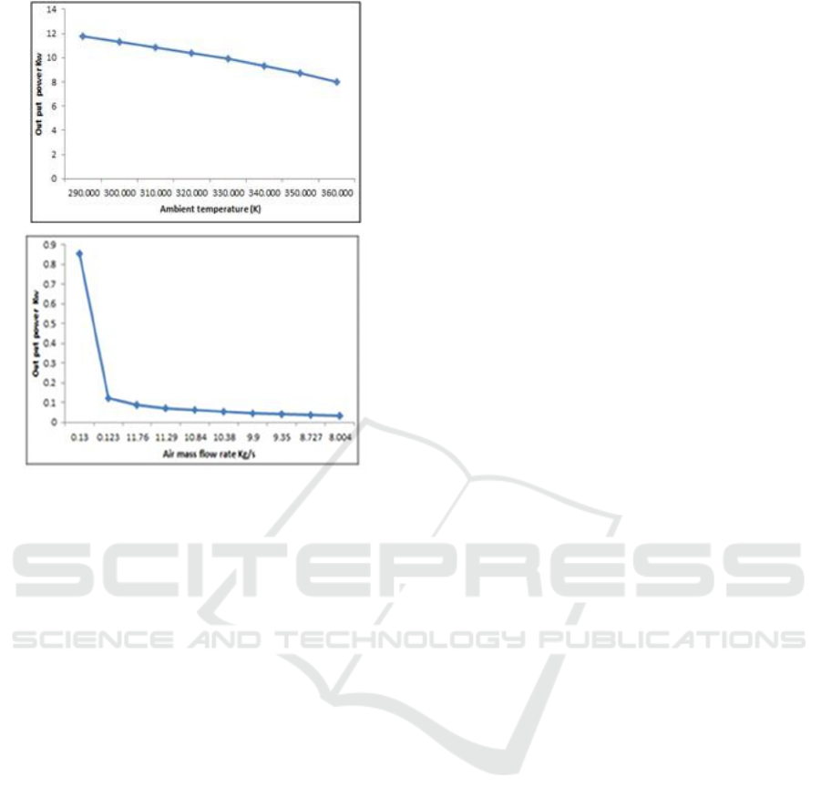
Figure 6: System output net power versus each input
Parameter (a) air mass flow rate (kg/s) and
(b) ambient temperature (K).
As shown as in Fig. 6a and b, the system output
net power increases evidently and linearly with the
increase of exhaust flow rate and temperature. In
other words, using the exhaust heat as much as
possible and the higher grade of heat source will
improve the system output net power according to
the calculations obtained, the energy produced by
the desulphurization system of phosphogypsum
(PG); the energy released by waste heat is 0.2 Mw <
waste heat < 200Mw so we apply our system to the
Rankine cycle.
3 CONCLUSION
The storage and management of a huge amount of
PG presents a serious problem on the environment,
so the objective of this work is to valorize the
thermal energy released by the desulfurization
system of the PG to produce electricity by applying
the cycle from Rankine.
REFERENCES
M. Canut, Belo Horizonte, Universidade Federal de Minas
Gerais, 2006.
C. A. Gregory, D. Saylak. W. B. Ledbetter, TRR Journal,
998, pp 47-52 (1984).
Bartow, FIPR Publication, 01, pp 124-119 (1996).
P. R Ernani, M. S. Ribeiro, C. Bayer, Sci. Agric., 58:825-
831, 2001.
P. A. Bellingieri, E.G. Bertin, L. Z. Mays, Científica, 31
pp 81- 89 (2003).
P. Bhawan, E.A. Nagar - Delhi: Central Pollution Control
Board, 2012.
G.A. Fattah, M.S. Altouq, A.A. Shamsaldien, Life Sci.,
13(3) (2016) 65-78.
S. Oumnih, E. K. Gharibi, E. B. Yousfi, N. Bekkouch, K.
El Hammouti, JMES, 2017 Volume 8, Issue 1, Page
338-344.
Chen H et al. A review of thermodynamic cycles and
working fluids for the conversion of low-grade heat.
Renew Sustain Energy Rev 2010. doi:10.1016/
j.rser.2010.07.00
Calm JM, Hourahan GC. Refrigerant data summary. Eng
Syst 2001;18(11):74–88.
Badr O, O’Callaghan PW, et al. Performances of Rankine
cycle engines as functions of their expanders’
efficiencies. Appl Energ 1984;18(1):15–27.
Badr O, O’Callaghan PW, et al. Rankine cycle systems for
harnessing power from low-grade energy sources.
Appl Energ 1990;36:263–92.
Lee KM, Kuo SF, Chien ML, et al. Parameters analysis on
organic Rankine cycle energy recovery system. Energ
Convers Manage 1988;28(2):129–36.
Lee MJ, Tien DL, Shao CT. Thermophysical capability of
ozone-safe working fluids for an organic Rankine
cycle system. Heat Recov Syst CHP 1993;13(7):409–
18.
Hung Tzu-Chen. Waste heat recovery of organic Rankine
cycle using dry fluids. Energ Convers Manage
2001;42:539–53.
Hung TC, Shai TY, Wang SK. A review of organic
Rankine cycles (ORCs) for the recovery of low-grade
waste heat. Energy 1997;22(7):661–7.
Liu BT, Chien KH, Wang CC. Effect of working fluids on
organic Rankine cycle for waste heat recovery. Energy
2004;29:1207–17.
Kribus A, Zaibel R, Carey D, et al. A solar-driven
combined cycle power plant. Sol Energy
1998;62(2):121–9.
Angelino G, Invernizzi C. Cyclic methylsiloxanes as
working fluids for space power cycles. J Sol Energ
Eng 1993;115:130–7.
Moustafa S, Hoefler W, El-Mansy H, et al. Deign
specifications and application of a 100 kWth
cogeneration solar power plant. Sol Energy
1984;32(2):263–9.
Gianfranco Angelino, Piero Colonna di Paliano. Organic
Rankine cycles (ORCs) for energy recovery from
molten carbonate fuel cells. American Institute of
Aeronautics and Astronautics; 2000. p. 2–11.
Ingwald Obernberger, Peter Thonhofer, Erwin
Reisenhofer. Description and evaluation of the new
1000 kWel organic Rankine cycle process integrated
ICCSRE 2018 - International Conference of Computer Science and Renewable Energies
40

in the biomass CHP plant in Lienz, Austria. Euroheat
Power 2002;10:1–17.
Weidao Shen, Zimin Jiang, Jungeng Tong.
Thermodynamics engineering. 3rd ed. China: Higher
Education Publishing Company; 2000.
Shilie Weng. Combustion turbine. China: Mechanical
Industry Publishing Company; 1989.
REFPROP Version 6.01, NIST Standard Reference
Database 23, the Secretary of Commerce, America;
1998.
Modelica Association. Specification, Tutorials [EB/OL],
http://
www.modelica.org/.
Dynasim AB, Dynamic Modeling Laboratory [EB/OL],
http://
www.dymola.com/.
Tchanche, B.F.; Lambrinos, G.; Frangoudakis, A.;
Papadakis, G. Low-grade heat conversion into power
usingorganic Rankine cycles – A review of various
applications. Renew. Sustain. Energy Rev. 2011, 15,
3963–3679. [CrossRef]
Bronicki, L. Short review of the long history of ORC
power systems. In Proceedings of the ORC2013,
Rotterdam, The Netherlands, 7–8 October 2013
Crook, A.W. Profiting from Low-Grade Heat; Institution
of Electrical Engineers: Stevenage, Hertfordshire,
1994.
Siemens. Fact Sheet: Organic Rankine Cycle. Available
online:
http://www.energy.siemens.com/nl/pool/
hq/power-generation/steam-turbines/orc
technology/Siemens_FactSheet-ORC-Module.pdf
(accessed on 1 May 2016).
Turboden. Organic Rankine Cycle Technology. Available
online: http://www.turboden.eu/en/public/
downloads/200-300%20kW.pdf (accessed on 5 April
2016).
Uusitalo, A.; Honkatukia, J.; Backman, J.; Nyyssönen, S.
Experimental study on charge air heat utilization of
large-scale reciprocating engines by means of organic
Rankine cycle. Appl. Therm. Eng. 2015, 89, 209–219.
[CrossRef]
MIROM. Verbrandingsinstallatie: enkele cijfers. Available
online: http://www.mirom.be/verbranding_
cijfers.html (accessed on 1 May 2017).
David, G.; Michel, F.; Sanchez, L. Waste Heat Recovery
Projects Using Organic Rankine Cycle Technology—
Examples of Biogas Engines and Steel Mills
Applications; World Engineers Convention: Geneva,
Switzerland, 2011.
Fernández, F.J.; Prieto, M.M.; Suárez, I. Thermodynamic
analysis of high-temperature regenerative organic
Rankine cycles using siloxanes as working fluids.
Energy 2011, 36, 5239–5249. [CrossRef]
Bao, J.; Zhao, L. A review of working fluid and expander
selections for organic Rankine cycle. Renew. Sustain.
Energy Rev. 2013, 24, 325–342. [CrossRef]
Stijepovica, M.Z.; Linke, P.; Papadopoulos, A.I.; Grujic,
A.S. On the role of working fluid properties in
Organic Rankine Cycle performance. Appl. Therm.
Eng. 2012, 36, 406–413. [CrossRef]
Maraver, D.; Royo, J.; Lemort, V.; Quoilin, S. Systematic
optimization of subcritical and transcritical organic
Rankine cycles (ORCs) constrained by technical
parameters in multiple applications. Appl. Energy
2014, 117, 11–29. [CrossRef]
Lecompte, S.; Huisseune, H.; van den Broek, M.; De
Paepe, M. Methodical thermodynamic analysis and
regression models of organic Rankine cycle
architectures for waste heat recovery. Energy 2016,
87, 60–76. [CrossRef]
Bell, I.H.; Wronski, J.; Quoilin, S.; Lemort, V. Pure and
pseudo-pure fluid thermophysical property evaluation
and the open-source thermophysical property library
CoolProp. Ind. Eng. Chem. Res. 2014, 53, 2498–2508.
[CrossRef] [PubMed]
Pacheco, J.E.; Showalter, S.K.; Kolb, W.J. Development
of a molten-salt thermocline thermal storage system
for parabolic trough plants. J. Sol. Energy Eng. 2002,
124, 153–159. [CrossRef]
Gamal A., Majida Sultan A. et AltafAbdulla S.,Life Sci.,
13(3) (2016) 65-78,
SfarFelfoul H., Clastres P. , Ben Ouezdou M., Carles-
Gibergues A. Proceedings of InternationalSymposium
on Environmental Pollution Control and Waste
Management 7-10 January 2002, Tunis (EPCOWM
(2002) 510-520.
Seidel G., Huckauf H., Starck J., Kerchove P. and
Chassard A., Technologie des ciments, chaux, plâtre
Ed. SEPTIMAZ-Paris, (1980)
Azimi G., Papangelakis V.G. and Dutrizac J.E., Fluid.
Phase Equilibr., 260 (2007) 300–315;
Daligand, Daniel. Plâtre. Ed. Techniques Ingénieur,
(2002).
Cooper J., Lombardi R., Boardman D. and Carliell-
Marquet C., Resour. Conserv. Recy.,57 (2011) 78–86,
Walan P., Davidsson S., Johansson S., Höök M., Resour.
Conserv. Recy.,93 (2014) 178–187,
Tayibi H, Choura M , A. Lopez F., J. Alguacil F., Lopez-
Delgado A., J. Environ. Manage., 90 (2009)
2377–2386,
Becker, P. (1989). Phosphates and phosphoric acid: raw
materials, technology, and economics of the wet
process. Revised and expanded (Vol. 6). Marcel
Dekker, Inc. ISBN :0824779762.
El Cadi A., Fakih Lanjri A., Lalilti A., Chouaibi N.,
Asskali A., Khaddor M.,J. Mater. Environ. Sci. 5 (S1)
(2014) 2223-2229, ISSN: 2028-2508,
Aliedeh M. A., and Jarrah A. N., Sixth Jordanian
International Chemical Engineering Conference,
Amman, Jordan (2012),
Hou Y., MA L., Zhang J. and Ning P.,Journal of
Kunming University of Science and Technology,
35(3), (2010),
Zhu Miao, Hairui Yang, Yuxin Wu, Hai Zhang, and Xuyi
Zhang., Ind. Eng. Chem. Res., 51(15) (2012)
5419-5423,
Guidelines for Management and Handling of
Phosphogypsum Generated from Phosphoric Acid
Plants. Central pollution control board, Delhi
India(2014).
Xie L. G., Ma L. P., Dai Q. X., Mao Y. Zhang H, and Ma
J.,Adv. Mat. Res.,726-731 (2013) 331-339
Heat Recovery Technology Applications for the Desulfurization Process of Phosphgypsum
41
