
Elaboration of the Minimum Capacitor for an Isolated Self Excited
Induction Generator Driven by a Wind Turbine
Fadi Ouafia, Abbou Ahmed
Mohammadia School of Engineers, Mohammed V University, Avenue Ibn Sina, Rabat, Morocco
Department of electrical engineering Mohammed V University, Rabat, Morocco
Keywords:
Wind turbine, Induction generator, self-excitation, excitation capacitance required, wind speed, magnetiz-
ing inductance, steady state, real parts of the roots, voltage build up, no load, prime mover, synchronous speed.
Abstract:
In this paper, a detailed procedure is elaborated, based on evaluation of the roots in the characteristic equation
of the stator current, to determine the proper capacitor bank that will be used to reach the self-excitation. For
that, a d-q model of the self-excited induction generator under no load is presented using Matlab-Simulink
to verify if the self-excitation comes true or not. This study illustrates furthermore, the influence of the
magnetizing inductance on the voltage buildup.
1 INTRODUCTION
A wind turbine with Self-excited Induction Genera-
tor SEIGs is a subject that is gaining renewed inter-
est with the increasingly frequent use of the asyn-
chronous generator. In the field of renewable ener-
gies, in general, and that of wind turbines, in particu-
lar, has largely contributed to the development of the
induction machine as a Self-excited Induction Gen-
erator thanks to its several advantages such as: very
reliable and relatively inexpensive compared to other
types of generators. It also has some mechanical char-
acteristics which makes it very suitable for the conver-
sion of wind energy (sliding of the generator as well
as a certain capacity of overload), very high lifetime;
non-existent maintenance (bearings ...), very simple,
rugged, and produces high power per unit mass (N.
M. Okana and al., 2015), (A.Abbou and al., 2013).
The self excited machine, in its operation in generator
mode, poses a particular problem : it cannot start it-
self as a generator and needs an external source to per-
form this operation which is called self-excitation : it
requires excitation current to magnetize the core and
produce the rotating magnetic field. This current is
supplied from an external source, for grid connected
systems; however, this current is supplied from a bat-
tery of capacitors, for isolated system which is our
case. When a charged capacitor is connected and the
generator is driven by a prime mover, a transient ex-
citing current will flow and produce a rotated mag-
netic flux, so as a result, the power will be generated
and supplied to the external source.
Several approaches have been reported in previous
studies to determine the sufficient value of the ca-
pacitance to stimulate a self excited induction gener-
ator (A.K and al., 1990), (N.H.Mal and al., 1986), (
N.H.Malik and al., 1987), (M.Orabi and al., 2000),
(S.S.Murthy al., 1982). Most of these approaches ap-
ply loop equations in the steady state model of per
phase equivalent circuit such us : Nodal Admittance
Approach, Loop Impedance Approach, and LC Res-
onance Principal. These kinds of approaches give the
appropriate capacitance corresponding to the mini-
mum capacitance in steady state analysis, but they are
inapplicable for transient analysis.
The main purpose of this study is to present a new
approach to determine the minimum capacitance re-
quired for excitation in a SEIG. For this, we should,
first look behind its process and extract an accurate al-
gorithm that will serve us to achieve the aim. For this,
we have, first, recalled the basic concepts for mod-
elling of RLC circuit, since this one is similar to the
self-excited induction generator. Then, a review of the
characteristic stator equation of the SEIG, the roots of
this equation is discussed as well as the choice of the
accurate capacitance.
264
Ouafia, F. and Ahmed, A.
Elaboration of the Minimum Capacitor for an Isolated Self Excited Induction Generator Driven by a Wind Turbine.
DOI: 10.5220/0009774302640270
In Proceedings of the 1st International Conference of Computer Science and Renewable Energies (ICCSRE 2018), pages 264-270
ISBN: 978-989-758-431-2
Copyright
c
2020 by SCITEPRESS – Science and Technology Publications, Lda. All rights reserved
2 SELF EXCITED INDUCTION
MACHINE
Basically, the mathematical model per phase of the
self-excited induction generator is similar to the clas-
sical induction motor; the only difference is that the
SEIG has a battery of capacitors linked to the stator
terminal.
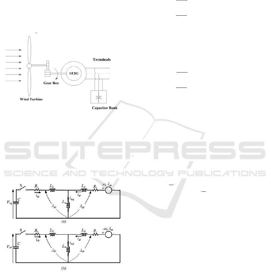
Figure 1: SEIG with a capacitor connecting across the
stator terminal.
The equivalent circuit representation of an asyn-
chronous machine is proper to use for steady state
analysis. Nonetheless, the Park representation is used
to model the SEIG beneath dynamic conditions.
Figure 2: Park representation of the self induction
generator in stationary frame (a) q-axis, (b) d-axis.
2.1 Modelling of the SEIG under No
Load
Using the d-q representation in Figure 2, the induction
machine can be modelled by equations (1) to (10),
From the stator side :
λ
ds
= L
s
i
ds
+ L
m
i
dr
(1)
λ
qs
= L
s
i
qs
+ L
m
i
qr
(2)
V
ds
= R
s
i
ds
+
dλ
ds
dt
(3)
V
qs
= R
s
i
qs
+
dλ
qs
dt
(4)
From the rotor side :
λ
dr
= L
r
i
dr
+ L
m
i
ds
(5)
λ
qr
= L
r
i
qr
+ L
m
i
qs
(6)
V
dr
= R
r
i
dr
+
dλ
dr
dt
+ ω
r
λ
qr
(7)
V
qs
= R
s
i
qs
+
dλ
qs
dt
− ω
r
λ
dr
(8)
For the air gap flux linkage side :
λ
dm
= L
m
i
ds
+ L
m
i
dr
(9)
λ
qm
= L
m
i
qs
+ L
m
i
qr
(10)
The matrix equation for the d-q model of a self
excited induction generator in the stationary stator
reference frame using the SEIG model is given by
(11).
R
s
+ pL
s
+
1
pC
0 pL
m
0
0 R
s
+ pL
s
+
1
pC
0 pL
m
pL
m
−ω
r
L
m
R
r
+ pL
r
−ω
r
L
m
ω
r
L
m
pL
m
ω
r
L
m
R
r
+ pL
r
i
qs
i
ds
i
qr
i
dr
+
V
cq0
V
cd0
−K
qr
K
dr
=
0
0
0
0
(11)
2.2 Analogy between RLC Circuit and
SEIG
Basically, an induction machine can be modelled us-
ing RLC circuit elements. In fact, the behaviour and
analysis of the self-excited induction generator is sim-
ilar to an RLC circuit.
2.2.1 RLC Circuit Approach
Energy can be stored in an inductor as well as in a ca-
pacitor, at t = 0, two initial conditions, current might
have been flowing in an inductor or initial voltage ex-
ist in a capacitor.
Elaboration of the Minimum Capacitor for an Isolated Self Excited Induction Generator Driven by a Wind Turbine
265
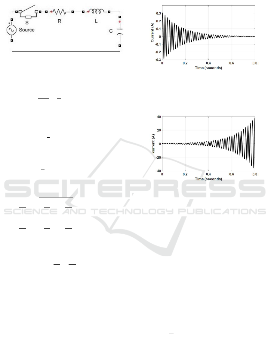
Figure 3: RLC circuitl.
Switch S is close : i(t) = 0; the voltage equation :
V
co
= Ri(t) + L
di(t)
dt
+
1
C
Z
i(t)d(t) (12)
Introducing the p operator (12) can be written as :
i(t) =
pV
co
pR + Lp
2
+
1
C
(13)
The characteristic equation is :
0 = pR + Lp
2
+
1
C
(14)
The roots of this equation are :
p
1
= −
R
2L
−
s
R
2L
2
−
1
LC
(15)
p
2
= −
R
2L
+
s
R
2L
2
−
1
LC
(16)
If we suppose that :
R
2L
≤
1
LC
Then the roots are complex, and can be expressed as :
p
1
= ψ + jΩ (17)
p
2
= ψ − jΩ (18)
ψ is always negative because the resistance R is posi-
tive, as result, with positive R will be a dampening of
oscillation, the real part ψ represents the rate at which
the transient decays, and Ω the imaginary part repre-
sents oscillation frequency.
In passive circuit like RLC all transient solutions have
a negative ψ meaning that transient is reduced with
the progression of time and finally will dampen to
zero.
Figure 4: progression of current for a positive resistance
value.
However, if ψ is positive, this implies the transient is
growing with the progression of time.
Figure 5: progression of current for a negative resistance
value.
We can describe the self-excitation in an induction
generator as the growth of current and the associated
increase in the voltage across the capacitor without an
external excitation system.
Transients that grow in magnitude (self-excitation)
with positive real part of the roots can only be happen-
ing if there is an external energy source that is able to
cover all the losses associated with the rising current,
the SEIG is able to have a growing transient because
of the external mechanical energy source.
2.2.2 Projection of the RLC Approach on the
SEIG
We can deal with the circuit of the SEIG by using the
same approach as well as the circuit of the RLC.
The matrix (11) can be written as :
R
s
+ pL
s
+
1
pC
0 pL
m
0
0 R
s
+ pL
s
+
1
pC
0 pL
m
pL
m
−ω
r
L
m
R
r
+ pL
r
−ω
r
L
m
ω
r
L
m
pL
m
ω
r
L
m
R
r
+ pL
r
i
qs
i
ds
i
qr
i
dr
=
−V
cq0
−V
cd0
K
qr
−K
dr
(19)
ICCSRE 2018 - International Conference of Computer Science and Renewable Energies
266
When a balanced three phase system is transformed
into a two-axis system, the stator currents i
qs
and i
ds
have similar waveforms.
i
qs
=
numerator
k
8
p
8
+ k
7
p
7
+ k
6
p
6
+ k
5
p
5
+ k
4
p
4
+ k
3
p
3
+ k
2
p
2
+ k
1
p
1
+ k
0
p
0
(20)
The characteristic equation of the current can be ob-
tained from the expression of the current transfer
function (20).
k
8
p
8
+ k
7
p
7
+ k
6
p
6
+ k
5
p
5
+ k
4
p
4
+ k
3
p
3
+ k
2
p
2
+ k
1
p
1
+ k
0
p
0
=0 (21)
With :
k
8
= A
2
k
7
= 2AB
k
6
= 2ADB
2
k
5
= 2BD +AE
k
4
= 2AF + 2BE + D
2
+ G
2
k
3
= 2BF + 2DE
k
2
= 2DF + E
2
k
1
= 2EF
k
0
= F
2
And :
A = C
L
2
r
L
s
− L
2
m
L
r
B = C
L
2
r
R
s
+ 2R
r
L
r
L
s
− L
2
m
L
r
D = C(2R
r
R
s
L
r
+ (R
2
r
+ ω
2
r
+ L
2
r
)L
s
− L
2
m
ω
2
r
L
r
) + L
2
r
E = CR
s
(R
2
r
+ ω
2
r
+ L
2
r
) + 2R
r
L
r
F = R
2
r
+ ω
2
r
+ L
2
r
G = CL
2
m
R
r
ω
r
This characteristic equation for the current can be
solved using different ways, for our case, the roots are
obtained numerically using the root function in Mat-
lab.
When (21) is factorized, it gives :
(p − ψ
1
+ jΩ
1
)(p − ψ
1
− jΩ
1
)
(p − ψ
2
+ jΩ
2
)(p − ψ
2
− jΩ
2
)
(p − ψ
3
+ jΩ
3
)(p − ψ
3
− jΩ
3
)
(p − ψ
4
+ jΩ
4
)(p − ψ
4
− jΩ
4
) = 0 (22)
If any of the roots in the equation has a positive real
value, then there is a self-excitation. To determine the
required capacitor for an induction generator running
at the given rotor speed, the roots values are computed
by increasing the capacitor value until one of the real
parts of the roots becomes positive.
2.3 Algorithm to Determine the
Minimum Capacitance
In order to determine the accurate capacitor value,
an algorithm is elaborated and programmed using
Matlab as shown in flow chart figure 6 :
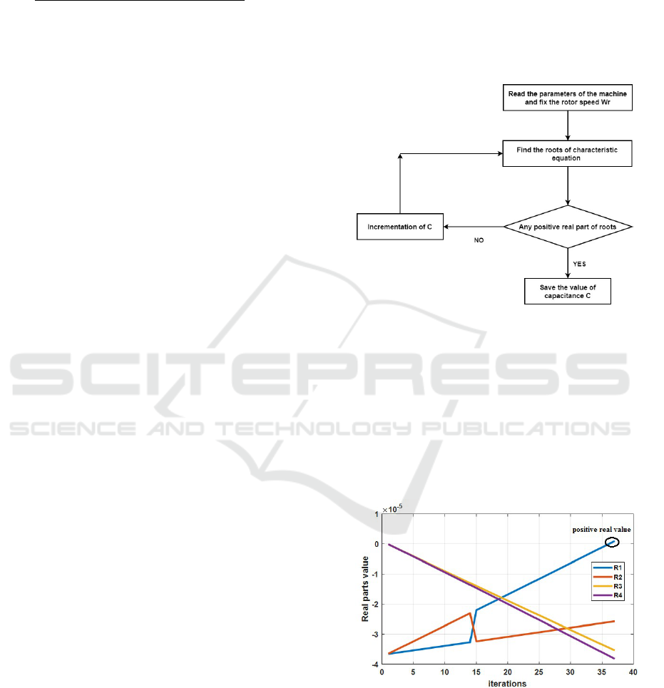
Figure 6: Flow chart to determine the minimum
capacitance at a given rotor speed at no load.
The minimum capacitance required for a given rotor
speed of induction generator, can be found by fixing
the rotor speed and then increasing the value of the
capacitance until one of the real parts of the roots be-
comes positive. The value of capacitance makes that
happen is the minimum value of capacitance required
for self-excitation.
Figure 7: progression of real part value when capacitance
C increased.
As it is shown in figure 7 all the real parts of the
roots start with a negative value, so the waveform will
dampen with time and there will be no transients. Af-
ter some iterations, the algorithm returns one of the
real part greater than zero and that by determining
Elaboration of the Minimum Capacitor for an Isolated Self Excited Induction Generator Driven by a Wind Turbine
267
the appropriate capacitance value that makes the self-
excitation achieve.
2.4 Characteristic of Magnetizing
Inductance
In the modelling of an induction machine, it is essen-
tial to determine the magnetizing inductance Lm at
rated voltage and rated frequency. In the SEIG, the
variation of Lm is the major element in voltage build
up and its stabilization. Magnetizing inductance is de-
termined by driving the asynchronous machine at syn-
chronous speed and taking measurements when the
applied voltage was varied from zero to 120% of the
rated voltage. The variation of Lm measured at rated
frequency of the induction machine used in this study
is given by (B.Singh al., 1998) :
L
m
= 0.00016I
3
m
− 0.002I
2
m
+ 0.005I
m
+ 0.205 (23)
The expression of Lm is elaborated experimentally as
a function of magnetizing current Im, however, in this
investigation, we are looking for the expression of
magnetizing inductance as a function of voltage V
0
,
for that, we use equations below to convert from L
m
=
f(I
m
) to L
m
= f(V
0
).
Z
0
=
q
R
2
s
+ ((L
s
+ L
m
)2π f )
2
(24)
V
0
= Z
0
I
m
(25)
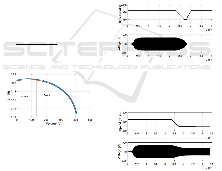
Figure 8: variation of Lm as function of voltage.
Where the blue dots are experimental results and the
red curve is a fourth order curve fit given by :
L
m
= −0.003V
4
0
− 0.01V
3
0
− 0.013V
2
0
− 0.02V
0
+ 0.19
The magnetizing inductance varies with voltage as
shown in Figure 8. At the start of self-excitation
where the voltage is near to zero, Lm is close to
0.205H. Once self-excitation begins, the generated
voltage will develop and thenL
m
also increases. When
there is an increase in L
m
, it increases the value of
the positive real root of the characteristic equation
and consequently the generated voltage grows faster.
Then, L
m
decreases while the voltage continues to
grow until it reaches its steady state value determined
by : the L
m
value, capacitance and the rotor speed.
2.5 Impact of Lm on Voltage Build-up
According to the previous figure, we can divide the
curve in stable an instable area B and A. If the SEIG
starts to generate in region A, a small loss in speed
will cause a drop in voltage and this will bring a de-
crease in L
m
, which in turn decreases the voltage, and
finally the voltage will dampen to zero. Once the volt-
age dampens, there is no transient phenomenon and
there will not be voltage build up even if the speed
increases once again to its initial value as shown in
figure 9.
Figure 9: decrease in rotor speed and its effect on
generation of voltage in the unstable area A.
Area B is a stable operating region. When the speed
of the prime mover decreases, voltage will decrease,
and L
m
increases, which yield the SEIG to continue to
operate at a lower voltage as shown in Figure 10.
Figure 10: reduction of the rotor speed and its impact on
generation of voltage in the stable area B.
The growth in L
m
means an increase in the positive
real roots of the characteristic equation.
ICCSRE 2018 - International Conference of Computer Science and Renewable Energies
268
3 SIMULATION RESULTE
The induction machine used as the SEIG in this study
is a three-phase induction motor with specifications
(APPENDIX-table 1). When the induction machine
is driven by a prime mover, the voltage will start to
develop at a corresponding minimum capacitance at
a giving rotor speed. This capacitance is obtained by
solving the roots of the 8th order polynomial equation
given by (21) and then searching if there is a positive
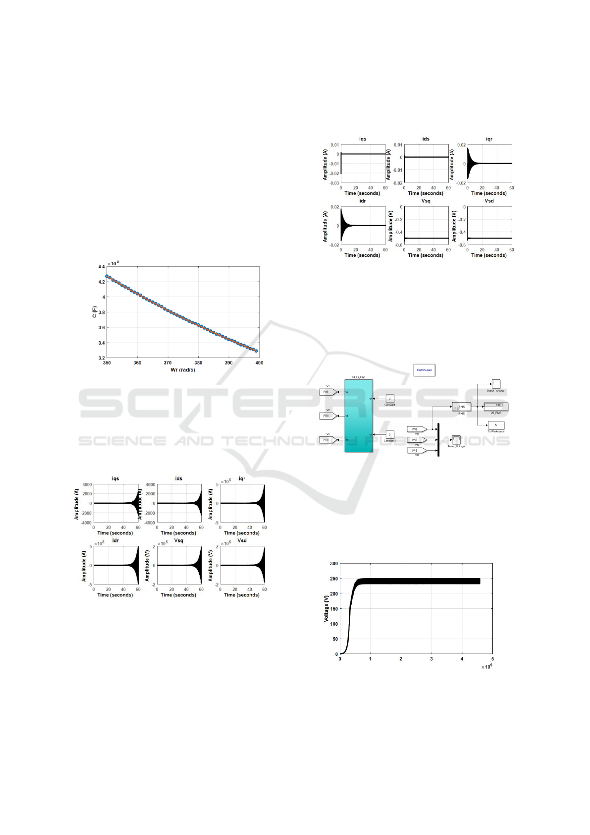
real part of the roots. The curve in figure 11 gives
the values of minimum capacitance at different rotor
speed at no load.
Figure 11: minimum capacitance as function of rotor speed
at no load.
In this investigation, the minimum capacitance re-
quired has a value of 35.3 µF . The figure 12 shows
the progression of different waveform of current and
voltage of the SEIG.
Figure 12: progression of current and voltage waveform
with capacitance value C = 35.3 µF.
As we notice the transients are growing with the pro-
gression of time, in theory, these transients will in-
crease to infinity, but in this case, it will increase
until the circuit is saturated so the self-excitation is
achieved. If we reduce the capacitance value from
35.3 µF to 30.5 µF the self-excitation does not come
true as shown in figure 13, and this value of 30.5
µF yield to a characteristic equation with roots which
have a negative real part.
Figure 13: progression of current and voltage waveform
with capacitance value C = 30.5 µF.
In order to visualize the voltage, a Simulink model of
the SEIG at no load is developed using matrix (19) as
shown in figure 14, this model gives us the possibility
to visualize the dynamic of our system and the impact
of capacitance value on voltage build up.
Figure 14: model of the SEIG at no load.
The voltage curve is given by the figure 15. Accord-
ing to this curve, we can notice that we have a voltage
build up at the choosing rotor speed and this validate
the value of capacitance giving by the algorithm de-
veloped in this study.
Figure 15: voltage progression of the SEIG at no load with
capacitance value of C = 35.3 µF.
To confirm that 35.5 µF is the minimum value, we re-
Elaboration of the Minimum Capacitor for an Isolated Self Excited Induction Generator Driven by a Wind Turbine
269
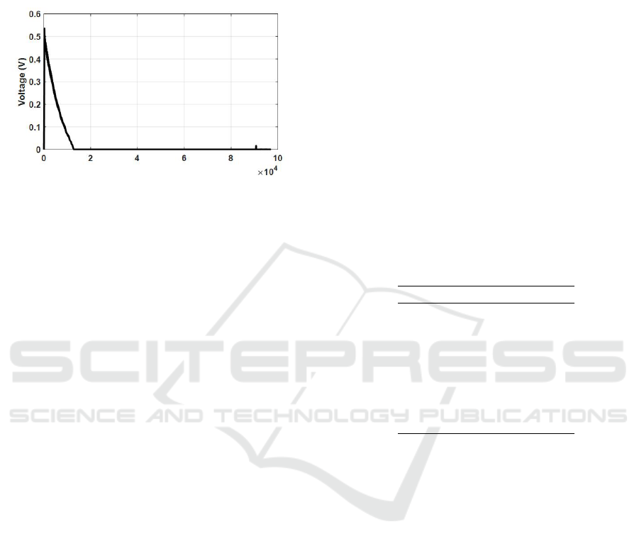
duce another time the capacitance value to 30.5 µF.
The figure 16 shows that the voltage collapses be-
cause the loss of the self-excitation phenomenon and
that return to the roots of the characteristic equation.
Figure 16: none build-up of the voltage of the SEIG at no
load with capacitance Value of C = 30.5 µF.
4 CONCLUSION
In this study, a simple algorithm is proposed to obtain
the minimum requirement of the capacitance for self
excited induction generator under no-load conditions
for different speeds. This study demonstrates, also,
how excitation capacitance and prime mover speed
affect the steady state performance of SEIG. The min-
imum value of the excitation capacitor must be prop-
erly calculated in order to assure an effective start-
ing of the SEIG. Furthermore, it was concluded that
SEIG has a critical excitation capacitor value at con-
stant rotor speed. We notice that the output voltage
magnitude follows the variation of the rotor speed,
decreasing the rotor speed will lead to decrease the
output voltage. This reveals the voltage regulation is-
sue of the self-excited induction generator when it is
used for wind application. Consequently, if our steady
state point is located in the stable area of Lm curve,
we can have proportionally between voltage and ro-
tor speed, however, if we are located in the instability
area a decrease in rotor speed will lead to a collapse
of the voltage, thereafter, demagnetization of our in-
duction machine.
REFERENCES
N. M. Okana ,T. Kamabu and P.T Tshani, “Self-excitation
study of an induction generator”, ACASTI, Vol 3, No
2, pp 57, september 2015.
A. Abbou, M. Barara, A. Ochatti, M. Akherraz, H. Mah-
moudi, “Capacitance required analysis for self-excited
induction generator”, JATIT, Vol 55, No. 3, pp 382,
September 2013.
A. K. Al. Jabri and A. L. Alolah “ Capacitor requirement for
isolated self-excited induction generator”, ZEE pro-
ceedings, Vol. 137, pt. B,No. 3, May 1990.
N. H. Mal and S. E. Haque “Steady state analysis and per-
formance of an isolated self excited induction genera-
tor” IEEE Trans. 1986,EC-1, (3). pp. 134-139.
N.H. Malik and A. A. Mazi “ Capacitance requirements for
isolated excited induction generators”, IEEE Trans.,
1987, EC-2 (I), pp. 62-69.
M. Orabi “design of wind energy conversion system”, MSc.
Electrical Engineering Department, Faculty of Engi-
neering, Elminia University, Elminia, Egvpt, 2000.
S. S. Murthy and N. H. Malilc and A. K. Tandon ”Analysis
of self excited induction generators”,ZEEproceedings,
Vol. 129, pt. C, No. 6, November 1982.
Bhim Singh and L. B. Shilpakar, “Analysis of a novel
solid state voltage regulator for a self-excited induc-
tion generator,” IEE Proc. Gener. Transm. Distrib.,
Vol. 145, No. 6, pp. 647-655, November 1998.
APPENDIX
Rated power 15 KW
Voltage 440V Y
Frequency 50 Hz
Pair pole 4
Rated speed 385 rd/s
Stator resistance 0.696 Ω
Rotor resistance 0.743 Ω
Inductance stator 1.1 mH
Inductance rotor 1.1 mH
Table 1: Induction generator parameters.
ICCSRE 2018 - International Conference of Computer Science and Renewable Energies
270
