
Study and Analysis of the Thermal Impact on the Overall
Performance of the Proton Exchange Membrane Fuel Cell and Its
Management and the Exploitation of PEM Fuel Cells in a
Cogeneration System: Review
Z. Hbilate, S. Hamham, Y. Naimi, D. Takky
Electrochemistry Team, Laboratory of Physical Chemistry of Materials, Faculty of Sciences Ben M'sik, University of
Hassan II Casablanca, Morocco
Keywords: PEM fuel cell, thermal management, heat, Cogeneration, environment.
Abstract: With the huge interest in clean energy development and the sources of production, appeared the development
of fuel cell technology as a clean source of energy which generates electricity releasing only water and heat
and which responds the most to the climatic requirement to perpetuate our environment. Current research
aims to the development and improving the performance and improving the performance as well as reducing
the cost to compete with other current sources of polluting energies. A proton exchange membrane fuel cell
has a lot of enticing characteristics however, in parallel to these distinctive and advantages, has also various
constraint and a considerable challenge to its widespread commercialization. That we will have to overcome
them to make it profitable and accessible, whose one of those challenges that requires the most effort is the
thermal management technology that makes this increasingly complex. In this review we will focus on the
study of the thermal management of the heat released inside the PEM fuel cell during operation and to study
the thermal impact on the performance of PEMFCs. As well as the possibility to rationalize the thermal energy
produced using the combined use of heat and energy cogeneration to maximize the energy produced and
improves the overall efficiency of the energy system.
1 INTRODUCTION
The need for energy will continue to increase
more and more, mainly following the metaphors and
the development of the industrial field which
consumes a huge part of world energies, which the
largely part comes from fossil energies, presents a
huge challenge and creates adverse undesirable
environmental effects, emissions at the local level and
overall greenhouse gases GHGs, what makes the
search for other alternatives a task that persists to
preserve our environment. In this order of ideas
renewable and clean energies remains as the most
appropriate solution to preserve our environment,
since they have the lowest carbon footprint (Naimi, et
al., 2016)and they are not harmful (Panwar, et al.,
2011) (Alper & Oguz, 2016).Of which their major
problem is the availability at the time of need which
is almost impossible because depends on several
climatic factors (Balat, 2008) (Viswanathan, 2017).
But in parallel with the development of this
technology, it turns out that another technology that
is also very promising and even if it is not a primary
source but just a carrier of energy, its hydrogen
technology (Harris, 2011). This technology boils
down to converting the potential energy produced by
renewable energy sites into hydrogen using an
electrolyzer. This technology can be summarized in
the fact to transform the potential energy generated by
the sites of renewable energy into hydrogen using an
electrolyzer. We use thereafter the Hydrogen
produced as needed to produce electricity, unlike the
electricity produced by renewable energies which is
not always available and depends on environmental
factors.
In the manner of renewable energies, the field of
fuel cells also remains as a highly promotive domain
that can respond to climatic and environmental
requirements. There are different types of fuel cells
which differs by several characteristics (materials,
electrolyte, fuel, ...) in our study we are interested in
PEMFC, due to its many advantages, like it is not
pollutant, doesn’t have a corrosive effect and it offers
Hbilate, Z., Hamham, S., Naimi, Y. and Takky, D.
Study and Analysis of the Thermal Impact on the Overall Performance of the Proton Exchange Membrane Fuel Cell and Its Management and the Exploitation of PEM Fuel Cells in a
Cogeneration System: Review.
DOI: 10.5220/0009772501150124
In Proceedings of the 1st International Conference of Computer Science and Renewable Energies (ICCSRE 2018), pages 115-124
ISBN: 978-989-758-431-2
Copyright
c
2020 by SCITEPRESS – Science and Technology Publications, Lda. All rights reserved
115

the highest energy density among the others (Lamei,
2012) (Zhang Liyan, 2011) (Zhidong, et al., 2015)
(Authayanun, et al., 2015), its low operating
temperature between 60 and 80 (Song W, 2014)
(Yan Z Y, 2013), Its low weight and volume and its
immediacy start (fast-star).What makes PEM fuel
Cell a promising candidate. However, although the
huge progress of PEMFC technology; the
development of fuel cells is still limited and presents
a lot of the difficulties and intrinsic problems to
overcome, which leading to the deterioration of
PEMFCs and directly affecting the overall yield of
the cell. In this perspective the thermal problem that
boils down in the temperature distribution and the
thermal management inner the fuel cell is presented
as one of the critical elements for an optimal
operation of the PEMFC. Therefore, our review
focuses in analyzing and managing this crucial
element to ensure the balance, stability and efficiency
of the PEM fuel cell. As well as studying the
exploitation of the PEM fuel Cell in a system of
cogeneration and analyzing namely the contextual, of
the global art system status and the technological
environment. In this paper we present a complete
analysis to study and analyze the influence of
temperature on the performance of the fuel cell and
also tools for its good management of this
determining parameter, in order to increase the
efficiency of the Fuel cell.
2 PRINCIPLE OF OPERATION OF
THE PEMFC
A fuel cell is an electrochemical device its
operating principle is to convert the chemical energy
stored in the fuel into electrical energy, the principle
of the fuel cell process can be described as the inverse
of the electrolysis of water. Indeed, this type of
battery can operate at room temperature and can
deliver a reasonable power for the intended
application. It is a controlled electrochemical
combustion of hydrogen and oxygen (Air) (Fig.1).
The only products of hydrogen decomposition and
oxygen reduction are water and heat formed as
secondary products with simultaneous generation of
electricity.
Both oxidation and reduction reactions (Eq.1)
(Eq.2) occur at the triple point areas which is located
at the interface between the electrolyte and electrode
with the presence of the catalyst (platinum) (Fig.1).
The only products of hydrogen decomposition and
oxygen reduction are water and heat formed as
secondary products with simultaneous generation of
electricity, according to the overall chemical reaction
(Eq.3).
Oxidation reaction:
→2
2
(1)
Reduction Reaction:
1
2
2
2
→
(2)
Overall reaction:
1
2
→
(3)
The theoretical potential delivered by a cell equal
to 1,23 and calculates by
≡
|
∆
|
(4)
E
th
: theoretical potential, ΔG: free enthalpy (Gibbs
energy of the reaction), F: Faraday constant.
To have a PEM fuel cell that generates a
significant amount of electricity must be assembled
several cells, in electrical series, which causes a lot of
difficulty in the management of the reaction products
during its operation of which the temperature increase
remain one of the important keys to the proper
functioning of the fuel cell that it has a decisive
impact, note that the thermal power produced is of the
same order of magnitude as the electrical power
(Alleau, Révision Octobre 2014). In this manuscript
we will study and detail the influence of the increase
of heat on the different components of the PEMFC.
ICCSRE 2018 - International Conference of Computer Science and Renewable Energies
116
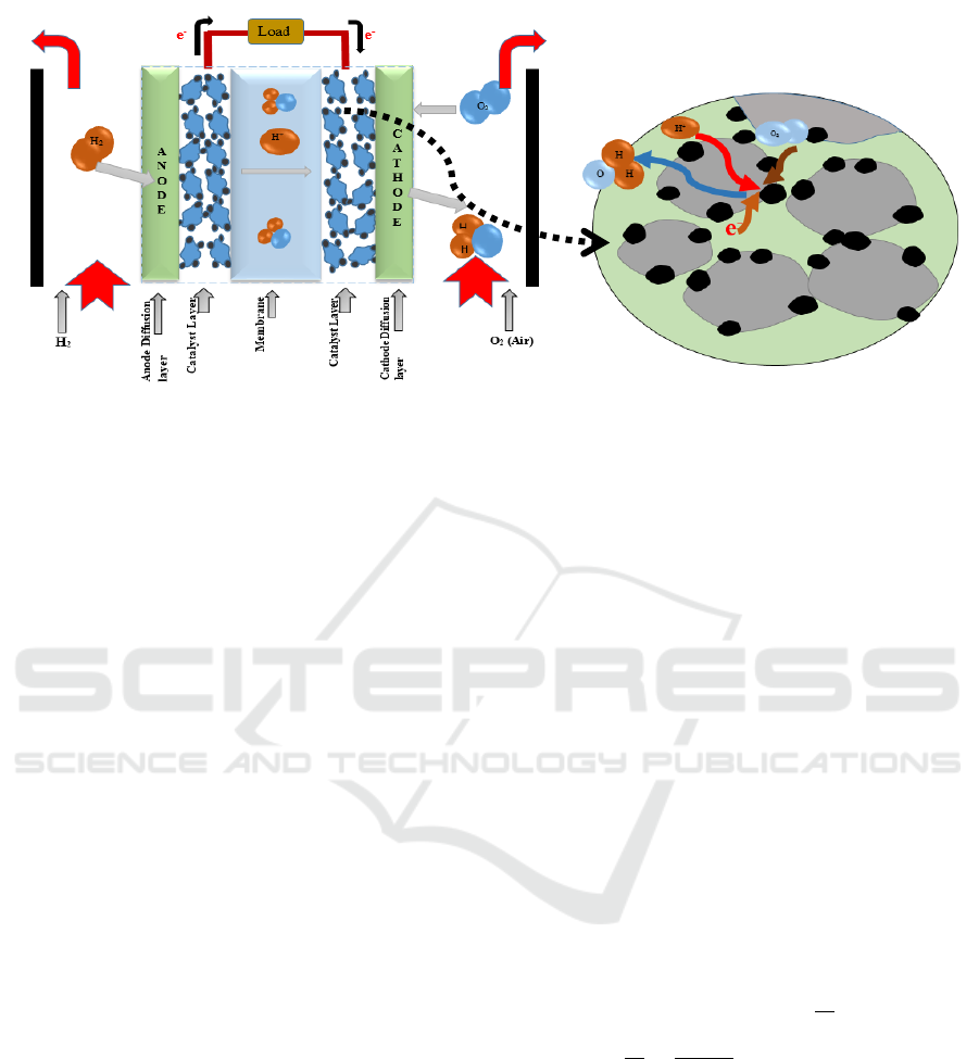
Figure 1: Schematic diagram of the operating principle and components of the membrane proton exchange fuel
cell (PEMFC) and the catalytic reaction at the electrode
3 THERMODYNAMIC AND
ELECTROCHEMICAL STUDY
The yield of PEM fuel cells generally does not
exceed 40% which implies the existence of a large
part of energy lost during the operation of the PEM
fuel cell and this mainly due to the electrochemical
reaction which is accompanied by several irreversible
losses. In practice, the existence of irreversible losses
will make the reactions exothermic. These losses are
actually, electricity transformed into heat.
These different types of losses that affects the
electrical efficiency and contribute to the increase of
dissipated energy as heat instead of electrical energy,
as the losses related to the transport of the different
reactant in the electrodes, the activation losses related
to reaction kinetics in the active layers, the losses
related to the transport of charges (Ohmic losses) in
the membrane (protons) and the electrodes (electrons)
which led to lowering the fuel cell yield.
The energy produced by the PEMFC specifically
comes from the thermodynamic energy that appeared
during the electrochemical reactions inside the cell.
Fundamentally, this energy comes from the
exothermic reaction of the water composition from H
2
and O
2
(Saeeda & Warkozekb, 2015) as in any
electrochemical component, only the free energy of
the reaction ΔG can be converted into electricity
(Eq.4), the maximum amount of electrical energy
produced in a PEM cell corresponds to the Gibbs free
energy.
ΔG = ΔH – TΔS (5)
ΔH: Enthalpy of the reaction, ΔS: The entropy of the
reaction. T: Operating temperature (K).
However, this energy is divided into two parts,
electrical and thermal energy, which the thermal
energy generated during operation exchanged with
the environment in the form of heat. The variation of
free enthalpy ΔG depends on the temperature, the
pressure, the conditions of the reaction and more
specifically reactants activities.
The Raising the temperature reduces voltage
losses, therefore a higher temperature led to a higher
cell voltage. However, an excessive local cell
temperature can cause dehydration of the membrane,
a contraction or even a rupture, which adversely
affects the proton conductivity which inversely
affects the course of the electrochemical reaction in
its turn. On the other hand, a low temperature is
unfavorable for the kinetics of the reaction, Because
it depends directly on the operating temperature, as
shows the Nernst equation of the reversible potential
which depends directly on pressure and temperature
(J. Bvumbe, et al., 2016) (Hosseinzadeh, et al., 2013)
(Ozbek, et al., 2013) (Yao, et al., 2004) (Pandiyan, et
al., 2008) (Authayanun, et al., 2015).
,
,
∆
ln
,
(6)
Pressure referential,
: hydrogen
pressure,
:oxygen pressure,
:pressure of H
2
O.
The internal thermal power produced during
operation of the cell defined as the difference
between, the chemical power released from the
reactants and the electrical power generated. The two
relations which follows, presents respectively the
chemical power (Eq.7) defined as the chemical
energy released by the hydrogen consumption and the
electric power (Eq.8)
Study and Analysis of the Thermal Impact on the Overall Performance of the Proton Exchange Membrane Fuel Cell and Its Management
and the Exploitation of PEM Fuel Cells in a Cogeneration System: Review
117

∆
∗
2
(7)
∗ (8)
The difference between the open circuit cell voltage
and the operating voltage, quantified as the amount of
energy dissipated as thermal power.
4 ENERGY AND THERMAL
PRODUCTION IN PEMFC AND
THE THERMAL DISTRIBUTION
IMPACT
4.1 Thermal Production and Joule Effect in
PEM Fuel Cell
The heat produced and released inside the stack
mainly due to the effect of the two terms one of which
is derived from the heat of the electrochemical
reactions as is already presented in the foregoing, and
the other of the Joule effect, due to the Ohmic
resistance of the components of the PEM fuel cell
assembly.
The joule effect in the membrane is caused by the
resistance to proton transfer and is reflected by a
volume heat source uniformly distributed in its
thickness, which is expressed by the following
relation:
(9)
: Overall resistance of the membrane.
A study conducted by (Pandiyan, et al., 2008) on
the thermal effect of the other components of the pile
show as a result of a difference of 10 of
temperature, it is properly clear that the thermal
resistance increases almost three times but on the
other side the current increases only by about 50%
which implies the existence of a high electrical
resistance in the components of the stack. It is clear
that the internal electrical resistance of the electrode
plays decisive role, Which decreases the current that
can be drawn from the PEM fuel cell for each increase
in unit temperature, which implies, in parallel with
the increase in electrical resistance an increase in the
effect, then more energy dissipated as heat, so the
characteristics of the electrodes materials have a
decisive role to decreasing the internal resistance. In
practice, the potential of a PEM cell is lower than the
theoretical potential due to internal losses in the fuel
cell (Haji, 2011). As we have already presented in the
foregoing part, the heat inside the fuel cell generates
mainly by the irreversibility of the electrochemical
reactions and the Ohmic resistance of the components
of the assembly of the stack (joule effect) (Pandiyan,
et al., 2008).The Heat also affects the distribution of
water by condensation and affects the gas diffusion
transport characteristics in multi-component by
thermo-capillary forces and thermal buoyancy
(Pandiyan, et al., 2008).
The overall yield of a PEMFC varies between
40% and 60% which implies the existence of a large
dissipation of chemical reaction energy which is
transformed into thermal energy that amount of
energy comparable to the electric energy. A study
(Alleau, Révision Octobre 2014)reported that the
thermal power to be removed is substantially the
same for a fuel cell (50% in heat and 50% in
electricity), Can go up to 100 kilowatts in automotive
applications (Kandlikar, et al., 2007) (Wen C.-Y.,
2011) (J. Bvumbe, et al., 2016). Another study
(Pandiyan, et al., 2008) has showed that the energy
produced inside of the cell comes out in the form of
thermal energy as much as electrical energy. For this
reason it is clear that for every decrease in operating
voltage we will have an increase in thermal output.
So, strictly speaking, for each temperature increase
we will have a decrease in current. On the other hand,
a study (Benmouiza & Cheknane, 2017) has clearly
demonstrated that a lower temperature directly affects
the performance of fuel cells and worsened the
voltage drop. In addition, it also shows that a high
temperature ensures rapid reaction that produces
more power. Furthermore, at higher temperatures, the
electrochemical reaction is faster, it increases the
water production in the cathode and better hydrates
the membrane, and thus the ionic resistance is
reduced.
The temperature clearly affects the performance
of the cell; generally adequate operating temperatures
are suitable for the efficiency of fuel cell. But in
parallel a high or low temperature can (Benmouiza &
Cheknane, 2017) amplify the degradation of PEM
fuel cell (J. Bvumbe, et al., 2016). As stated above a
study (Pandiyan, et al., 2008)also clearly stated that
the operating temperature has a decisive impact on
the kinetics of electrochemical reactions and its
distribution in the cell affects the performance. The
same work has shown that the ratio between the
electrical output power and the thermal output is
unitary. However, when the operating voltage of the
cell decreases, the ratio increases to 2 for an operating
voltage of 0.5 V. This shows that twice the energy
goes out as heat instead of the electrical output. This
also supports the studies presented previously.
Several studies have shown that the electrode
manufacturing process also has a very important role
in reducing the internal resistance of the cell in
addition to its components the effect of the electrical
ICCSRE 2018 - International Conference of Computer Science and Renewable Energies
118

and thermal resistance of a PEM fuel cell has been
evaluated (Pandiyan, et al., 2008)and has been
observed that the increase in thermal resistance is
three times and the current increases by 50% for a
temperature change of 10 .Confirming that the
internal resistance of the electrode increases by the
increase of the current density with respect to
temperature change. Then an adequate temperature
within the cell is highly useful for the improvement
of the kinetics of the electrochemical reaction and the
ion transport which gives the improvement of the
performances by means of the reduction of the
voltage losses. That’s why, it is necessary to handle
and control the heat produced inside the fuel cell. As
well as to manage well its distribution in the various
components of the PEM fuel cell.
4.2 Temperature Distribution in the PEM
Fuel Cell
The temperature distribution in PEM Fuel Cell is
recognized as an important factor for fuel cell
stability and efficiency. Because there is a generally
fractional relation between temperature and heat
diffusion in semi-solid systems such as fuel cell. To
avoid amplification of the deterioration of the fuel
cell, the lowering of its performance in general, as
well as the membrane in a specific way and make it
last. This is why we must think of eliminating the
excess heat produced, effectively to ensure good
thermal distribution inside. Part of this heat is
spontaneously dissipate either by convection and
radiation to the environment, or by unused reactants.
But this part remains nevertheless low by contribution
to the heat produced. As well as when the temperature
is high these evacuation modes are negligible, which
can be thought of dissipated by active cooling to
prevent overheating of the PEMFC. In this
perspective, several studies have studied the effect of
forced cooling. Who let’s think of the dissipated by
active cooling to avoid overheating of the PEMFC.
5 OVERALL THERMAL
MANAGEMENT OF THE SYSTEM
5.1 Adverse Thermal Effect on the
Membrane and Its Management
Concerning the membrane and its proper
functioning, we must clearly keep a good balance
between its temperature and its hydration which many
studies have investigated this point in the fuel cells.
From a theoretical point of view, a fuel cell involves
an exothermic reaction. Due to the different losses
that we have already described in advance, which
generates a fairly large amount of temperature which
heats all of the components, so beyond this point,
there is a surplus of heat that must be released towards
the outside of the component. And it will cool the
component in order to not destroy the membrane,
because the current membranes do not withstand
temperatures higher than 90 (Rallieres, 2011). So,
an improper thermal management will induce various
thermal problems. As dehydration of electrolyte as
well as the problem of overflow in the cathode, which
imposes more critical challenges on the PEMFC
operation.
On the one hand the cathode overflow
phenomenon has been the subject of many studies
(Lampinen & Fomino, 1997) (Eikerling, 2006) (Abd
Elhamid, et al., 2004) (Shimoi, et al., 2004) (Yu, et
al., 2006) (Zong, et al., 2006) (Kandlikar & Lu,
2009)which (Kandlikar & Lu, 2009)has exhibited that
the phenomenon of overflowing is strongly affected
by the distribution of temperature due to its
dominance of condensation / evaporation process in
the cathode. On the other hand, several causes have
been identified for the dehydration of PEMFC which
increases the proton conduction resistance. A
relatively low humidification, a high stoichiometric
ratio with either a high temperature or just a high
temperature can easily cause the membrane as a
subject of dehydration. An electroosmotic drag, a
displacement of the water molecules from the anode
to the cathode by a proton flow also leads to
dehydration. Like the other difficulties presented,
another thermal imposing problem is the non-uniform
temperature distribution in the membrane, which
exists both through the membrane (Maes & Lievens,
2007) (Lampinen & Fomino, 1997) (Eikerling, 2006)
(Berning & Djilali, 2003) (Gloaguen & Durand,
1997) (Kandlikar & Lu, 2009)and along the flow
length (Jordan, et al., 2000) (Kandlikar & Lu, 2009).
This non-uniformity of temperature, of the order of
many degrees, has a considerable impact on the water
content of the membrane and the uniformity of
current density (Meyers, et al., 2006) (Wilkinson &
Vanderleeden, 2003) (Kandlikar & Lu, 2009). But it
always remains a need to have an adequate
temperature to lead to an improvement of the kinetics
of the electrodes as well as the increase of the ionic
conductivity in the membrane and the electrodes thus
the improvement of power density (Ferng, et al.,
2003).A study (Odne, et al., 2014) showed that the
thermal conductivity in the membrane clearly
depends on the water content, and we will have a 50%
Study and Analysis of the Thermal Impact on the Overall Performance of the Proton Exchange Membrane Fuel Cell and Its Management
and the Exploitation of PEM Fuel Cells in a Cogeneration System: Review
119

increase in thermal conductivity when the catalytic
layer is fairly saturated. Thus an increase of 33%
temperature difference between the gas flow field
plates and the PEM fuel cell, with a catalytic layer
moderately moistened. A high proton conductivity
depends essentially on the water content of the
membrane (Ben-Attia, 2013). Nevertheless, we have
a great correlation between water content and thermal
conductivity in the membrane (Burheim, et al., 2010)
(Burheim, et al., 2011). The presence of water is
known by increasing the thermal conductivity of the
Porous Transport Layer (Burheim, et al., 2011)
(Wang & Gundevia, 2013) (Burheim, et al., 2013)and
the membrane of the PEM fuel cell (Burheim, et al.,
2010) (Khandelwal & Mench, 2006) (Odne, et al.,
2014). This problem is the subject of many works in
order to minimize a study of (Paul, et al., 2011)
presented that among the suggested measures is to
take in consideration the water content in the
materials of the membrane as well as the thickness of
the membrane, because more the membrane is thin
the water content and the conductivity of the protons
also fluctuate.
We realize that to have a good functioning of the
cell and have the best performance, we will have to
manage the amount of heat and the water content in
order to maintain the best operating conditions of the
membrane and ensure a balance between the water
and humidification rate, while keeping a necessary
amount of heat to satisfy the proper functioning.
5.2 Efficient Management and
Evacuation of the Thermal Power
Produced Inside the PEM Fuel Cell
System
Generally, as described above, in the fuel cell the
electric power supplied is almost the same as the
thermal power and must be evacuated to avoid
overheating hence the degradation of the components
of PEM fuel cell and especially the membrane. An
appropriate thermal management of the heat
generated inside the cell ensures a uniform
distribution in space and time in order to avoid high
temperature points in the cell generally and
specifically in the membrane, as well as to ensure a
higher electrical efficiency. Therefore the cooling
system must be efficient and ensure a proper coolant
circulation and provide a more uniform temperature
distribution in the stack of fuel cell (Ravishankar &
Arul Prakash, 2014)to optimize the system and
ensuring a high overall cell yield (Pandiyan, et al.,
2008). In the same vision a study carried out (Rojas,
et al., 2015)has showed that a good distribution of
water channels can homogenize the temperature
variation throughout the stack. So following the effect
of cooling by the distribution of water in the channels,
the temperature of the cells in a Stack is fairly similar
and that the greatest temperature difference is close to
the last plates (In the first cell, the temperature is
higher due to the lack of water channels between the
first side plate and the first cell. And that the last cell
of the series has a lower temperature, because of the
presence of water channel, and there is no production
of electricity between the last cells in the second side
plate). This study clearly stated that heat can be
dissipated in an effectively by this cooling system
achieve, this method has prevented overheating of the
cells to ensure the stability of operation and to
maintain the cell. But the effectiveness of this system
cells must be under operating conditions identical to
each other. What in reality is not feasible for different
reasons such as the location of the cell and channel
cooling and the general design of the fuel cell,
therefore a control system is strongly recommended
to ensure the efficiency in order to properly maintain
and control the uniform distribution of heat (Strahl, et
al., 2014) (J. Bvumbe, et al., 2016). Moreover, a
poorly designed cooling system accelerates the
general deterioration of the components of PEM fuel
cell, involving the lowering of the overall yield, that
means a good thermal management maintain the
overall system functionality and improves the overall
yield. In this context the study by (Alleau, Révision
Octobre 2014)proposed some measures in order to
successfully achieve heat evacuation, firstly one of
the essential is to ensure a circulation of a coolant in
the bipolar plates every 2 to 3 cells, then for a more
efficient heat evacuation, we can equip the bipolar
plates with the cooling fins to promote its cooling, put
a system of forced circulation of air to the outside, as
well as the injection of the air humidify with water at
the entrance of the PEMFC which will remove an
amount of heat by partial evaporation.
The system must be continually examined to
ensure the durability of the different functions of all
components by a control set. In addition to ensure
proper functionality of the membrane and have a
good protonic conduction, we will have to ensure
both a temperature distribution and an adequate
humidification, as well as appropriate drainage of the
water produced by the reaction during operation by
an air flow introduced to the cathode. This airflow
must be important for a better distribution of the
oxygen concentration and for the drainage of
produced water. One last point to have a good
performance and better performance in each cell of
the PEMFC we will have a supply of pure hydrogen
ICCSRE 2018 - International Conference of Computer Science and Renewable Energies
120
and oxygen in order to have optimal operation (Baek,
et al., 2011). A very high purity of gases is required,
because the membrane / electrode assembly is
extremely sensitive to all impurities in the water
(Varkaraki, et al., 2003) (Colliera, et al., 2006)
(RABIH, 2008).The more pure the reactants, the
more we will not have impurities which hinders the
reactions in both electrodes reaction, which implies
optimal functioning.
6 HEAT AND POWER
COMBINATION
(COGENERATION) (CHP)
The catalytic oxidation during operation of the
PEM fuel cell is an exothermic reaction, therefore this
oxidation generates a very significant amount of
energy as heat. Its temperature generally ranges from
60 to 80 ° C, that we must adapt it effectively to avoid
overheating the PEMFC. On other hand all the same
we need to keep an adequate temperature for the
system to ensure proper functioning. The figure
(Fig.3) shows the overall distribution of thermal
evacuation, while a part evacuated by the reagent of
overloading a second part by spontaneous heat
transfer, as well as a part is dissipated by vaporizing
some of the water produced and the remaining part of
heat requires an appropriate cooling system.
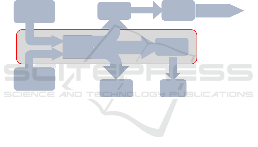
Figure 2: Fuel cells used in CHP application.
The temperature difference between the PEMFC
and the ambient temperature of the environment
constitutes a challenge for the design of a slight
cooling system that can work in a desirable manner
(Kandlikar & Lu, 2009) (Rogg, et al., 2003) (Islam, et
al., 2015). But although the principle of cooling is
simple, its implementation is a real industrial and
technological challenge. The production of the
electricity by PEM fuel cell always leads in parallel
to a heat generation. With an energy conversion
efficiency that tends to 55% (Islam, et al., 2015). This
implies the existence of a fairly large amount of
produced heat that is in the same order of the
electrical power (Barbir, et al., 2005) (Tekin, et al.,
2006). So in this case appear the interest of exploiting
the heat generated by the PEM fuel cell in a system of
cogeneration (combined heat and power CHP). The
technology of cogeneration manifests itself as a better
solution to avoid the energy dissipation, Whose the
overall interest of the use of the technical CHP is lies
in the possibility of reusing the heat generated in the
other applications combined heat and power (CHP)
(Fig.2).
In the case of PEM fuel cell, cogeneration is an
ideal way to use residual heat generated, during fuel
cell operation to improve its efficiency. The
cogeneration has a very efficient form of energy
conversion that can improve yields by over 90%. The
overall efficiency of cogeneration is the sum of net
electrical and thermal efficiency of cogeneration
systems operated.
Several researches carried out around this subject
which showed the interest of this technology, one of
them (Hubert, 2005) showed that the fuel cell
(PEMFC) is a promising technology not just an the
huge system of cogeneration but also mainly for
micro-Cogeneration (CHP).For several years, the
Hydrogen
Oxygen (Air)
System
boundary
PEM
Fuel Cell
DC Power
Converter
DC/AC
Heat
stora
g
e
Heating
Installation
CHP
AC
Powe
r
Heat
Supply
Exhaust
Gas
Study and Analysis of the Thermal Impact on the Overall Performance of the Proton Exchange Membrane Fuel Cell and Its Management
and the Exploitation of PEM Fuel Cells in a Cogeneration System: Review
121

research is moving towards this energy sector and
especially gas companies and Japanese industrial
groups are very active in research and development
on the use of PEMFCs for micro-cogeneration (Inaka
& Al, 2002) (Geiger & Cropper, 2003) (Hubert,
2005).In order to have a qualitative and quantitative
understanding of this type of system; many research
projects are carried out on PEMFC operated on
cogeneration in several European countries such as
Belgium and Germany (Pokojski, 2004) (Frey, et al.,
2004), these projects have been able to deliver good
electrical efficiencies that have been able to go up to
38% and 40% of thermal efficiency. Nevertheless, in
parallel with these progress different technical
complications and the high operating and
maintenance costs have occurred to limit its
exploitation. The cogeneration technology remains
unmatched in terms of efficiency and yield in this
power field. The study of (Hubert, 2005) has
exhibited that small stationary fuel cell systems
powered by natural gas and exploited in cogeneration
are at a phase of technological and commercial
development which suggests a close
commercialization if we manage to reduce its high
cost and stringent maintenance requirements which
prevent it from being widely marketed.
Figure 3: Sankey diagram of the energy distribution produced by the PEMFC (Islam, et al., 2015)
7 CONCLUSION
A large amount of thermal energy has been
retained in the stack, so it is necessary to evacuate this
energy to avoid excessive heating, which can lead to
many problems. In this manuscript we showed and
analyzed the influence of the heat produced inside the
PEM fuel cell and the tools for leading to the
dissipation of this thermal energy, to avoid
precipitous deterioration of the PEM fuel cell. As well
as s the possibility of exploiting it by cogeneration in
another system, in order to avoid losses and achieve
higher profits from the chemical energy wasted in the
form of thermal energy instead of electrical during
reaction. So the use of residual heat produced by
PEMFC that is normally rejected by conversion
systems. Cogeneration technology is one of the
promising solutions, having real potential to save
primary energy and improve overall yield. The main
reason for this potential is to save primary energy and
exploit the thermal energy instead of throwing it
away. Finally, we generally realize that the
improvement of the materials used, the optimization
of the overall operation and the knowledge of the
phenomena taking place in the heart of the pile, these
are the keys to better optimization for the system but
still require significant research efforts. This study
allowed us to have a good understanding on the
manipulation of the different parameters influencing
the thermal management during operation As well as
to understand what is happening inside the studied
environment. Although the operating principle of the
fuel cell is simple, its implementation remains a real
industrial and technological challenge.
Hydrogen
Excess Hydrogen
(5%)
Power (50%)
Heat (45%)
Heat removal by
extra reactants (2%)
Heat used by the FC
internally for water
evaporation (5%)
Heat removal by
cooling system
Heat removed by natural
convection from the
body of the FC if the
stack is water cooled
ICCSRE 2018 - International Conference of Computer Science and Renewable Energies
122

REFERENCES
Abd Elhamid, M., Mikhail, Y., Blunk, R. & Lisi, D., 2004.
Inexpensive dielectric coolant for fuel cell stacks. US
Patent 6,740,440, assigned to General Motors
Corporation.
Alleau, T., Révision Octobre 2014. Mémento de
l’Hydrogène la pile à combustible de type PEM, s.l.:
Fiche 5.2.2 Source: AFHYPAC.
Alper, . A. & Oguz, O., 2016. The role of renewable energy
consumption in economic growth: evidence from
asymmetric causality. Renew Sustain Energy Rev.
Authayanun, S., Im‐orb, K. & Arpornwichanop, A., 2015.
A review of the development of high temperature
proton exchange membrane fuel cells. Chinese journal
of catalysis, p. 473–483.
Baek, S., Yu, S., Nam, J. & Kim, C., 2011. A numerical
study on uniform cooling of large-scale PEMFCs with
different coolant flow field designs. Appl. Therm. Eng,
p. 1427–1434.
Balat, M., 2008. Potential importance of hydrogen as a
future solution to environmental and transportation
problems.. Int J Hydrogen Energy.
Barbir, F., Molter, T. & Dalton, L., 2005. Efficiency and
weight trade-off analysis of regenerative fuel cells as
energy storage for aerospace applications.. Int J
HydrogenEnergy.
Ben-Attia, H., 2013. Elaboration et caractérisation des
membranes à base de Nafion® / H3 et Nafion® / H1
pour les piles à combustible, France: Université de
Grenoble.
Benmouiza, K. & Cheknane, A., 2017. Analysis of proton
exchange membrane fuel cells voltage drops for
different operating parameters. International Journal of
Hydrogen Energy.
Berning, T. & Djilali, N., 2003. A 3D multiphase,
multicomponent model of the cathode and anode of
aPEM fuel cell. J. Electrochem. Soc. 150, p. A1589–
A1598.
Burheim, O. et al., 2013. Ageing and thermal conductivity
of porous transport layers used for PEM fuel cells. J
Power Sources.
Burheim, O. et al., 2011. Through-plane thermal
conductivity of PEMFC porous transport layers.
Journal Fuel Cell Sci Technol.
Burheim, O., Vie, P., Pharoah, J. & Kjelstrup, S., 2010. Ex-
situ measurements of through-plane thermal
conductivities in a polymer electrolyte fuel cell.. J
Power Sources.
Colliera, A. et al., 2006. Degradation of polymer electrolyte
membranes. International Journal of Hydrogen
Energy, pp. 1838-1854.
Eikerling, M., 2006. Water management in cathode catalyst
layers of PEM fuel cells: a structure-based model.
Journal Electrochem Soc 153.
Ferng, Y., Sun, C. & Su, A., 2003. Numerical simulation of
thermal–hydraulic characteristics in a proton exchange
membrane fuel cell. Internatonal journal of energy
research, Issue (DOI: 10.1002/er.891), p. 495–511.
Frey, H., Edel, M., Kessler, A. & Munch, W., 2004.
Stationary fuel cells at EnBW. Belfort, s.n.
Geiger, S. & Cropper, M., 2003. Fuel Cell Market Survey:
Small Stationary Applications. Fuel Cell Today.
Gloaguen, F. & Durand, R., 1997. Simulations of PEFC
cathodes: an effectiveness factor approach. Journal
Appl Electrochem, p. 1029–1035.
Haji, S., 2011. Analytical modeling of PEM fuel cell ieV
curve. Renew Energy.
Harris, A., 2011. Clean energy: resources, production and
developments. Nova Science Publishers.
Hosseinzadeh, E., Rokni, M., Rabbani, A. & Mortensen, H.,
2013. Thermal and water management of low
temperature Proton Exchange Membrane Fuel Cell in
fork-lift truck power system. Appl Energy, p. 434–444.
Hubert, C., 2005. Étude du fonctionnement et optimisation
de la conception d’un système pile à combustible PEM
exploité en cogénération dans le bâtiment, s.l.: École
Nationale Supérieure des Mines de Paris.
Inaka, H. & Al, 2002. The development of effective heat
and power use technology for residential in a PEFC co-
generation system. J. power sources, pp. vol. 106, p.
60-67.
Islam, M., Shabani, B., Rosengarten, G. & Andrews, J.,
2015. The potential of using nanofluids in PEM fuel
cell cooling systems: A review. Renewable and
Sustainable Energy Reviews, p. 523–539.
J. Bvumbe, T. et al., 2016. Review on management,
mechanisms and modelling of thermal processes in
PEMFC. Hydrogen and Fuel Cells, p. 1–20.
Jordan, L. et al., 2000. Effect of diffusion-layer morphology
on the performance of polymer electrolyte fuel cells
operating at atmospheric pressure. J. Appl.
Electrochem., p. 641–646.
Kandlikar, S. G. & Lu, Z., 2009. Thermal management
issues in a PEMFC stack – A brief review of current
status. Applied Thermal Engineering, p. 1276–1280.
Kandlikar, S. & Lu, Z., 2009. Fundamental research needs
in combined water and thermal management within a
proton exchange membrane fuel cell stack under
normal and cold startconditions. Journal Fuel Cell Sci
Technol.
Kandlikar, S., Lu, Z. & Trabold, T., 2007. Current Status
and Fundamental Research Needs In Thermal
Management within a PEMFC Stack. Edinburgh,
Scotland, s.n.
Khandelwal, M. & Mench, M., 2006. Direct measurement
of through plane thermal conductivity and contact
resistance in fuel cell materials. J Power Sources.
Lamei, X., 2012. Simulation and Optimization of Proton
Exchange Membrane Fuel Cell. Beijing: Beijing:
national defence industry press.
Lampinen, M. & Fomino, M., 1997. Analysis of free energy
and entropy changes for half-cell reactions. J.
Electrochem. Soc, p. 3537–3546.
Maes, . J.-P. & Lievens, S., 2007. Methods for fuel cell
coolant systems. U.S. Patent 7,201,982, assigned to
Texaco, Inc.,.
Meyers, . J.-P.et al., 2006. Evaporatively-cooled PEM fuel
cell stack and system. ECS Trans, p. 1207–1214.
Study and Analysis of the Thermal Impact on the Overall Performance of the Proton Exchange Membrane Fuel Cell and Its Management
and the Exploitation of PEM Fuel Cells in a Cogeneration System: Review
123

Naimi, Y., Saghir, M., Cherqaoui, A. & Chatre, B., 2016.
Récupération énergétique de la biomasse dans la région
de Rabat, Maroc. International Journal of Hydrogen
Energy.
Odne, S. et al., 2014. Study of thermal conductivity of PEM
fuel cell catalyst layers. international journal of
hydrogen energy, pp. 9397-9408.
Ozbek, M., Wang, S., Marx, M. & Soffker, D., 2013.
Modeling and control of a PEM fuel cell system: a
practical study based on experimental defined
component behavior. J Process Control.
Pandiyan, S., Jayakumar, K., Rajalakshmi, N. &
Dhathathreyan, K., 2008. Thermal and electrical energy
management in a PEMFC stack – An analytical
approach. International Journal of Heat and Mass
Transfer, p. 469–473.
Panwar, N., Kaushik, S. & Kothari, S., 2011. Role of
renewable energy sources in environmental protection..
Renew Sustain Energy Rev.
Paul, D., Fraser, . A. & Karan, K., 2011. Towards the
understanding of proton conduction mechanism in
{PEMFC} catalyst layer: conductivity of adsorbed
nafion films. Electrochemistry Communications.
Pokojski, M., 2004. Die erste 250 kW PEM Brennstoffzelle
in Europa -Betriebserfahrungen, s.l.: s.n.
RABIH, S., 2008. Contribution à la modélisation de
systèmes réversibles de types électrolyseur et pile à
hydrogène en vue de leur couplage aux générateurs
photovoltaïques, Toulouse: doctorats de l’université de
Toulouse l’institut national polytechnique .
Rallieres, O., 2011. Modélisation et caractérisation de
Piles A Combustible et Electrolyseurs PEM. Energie
_électrique, Toulouse: Institut National Polytechnique
INPT.
Ravishankar, S. & Arul Prakash, K., 2014. Numerical
studies on thermal performance of novel cooling plate
designs in polymer electrolyte membrane fuel cell
stacks. Appl Therm Eng, p. 239–251.
Rogg, S. et al., 2003. Cooling modules for vehicles with a
fuel cell drive. FuelCells.
Rojas, J. D., Kunusch, C., Ocampo-Martinez, C. & Puig,
V., 2015. Control-oriented thermal modeling
methodology for water-cooled PEM fuel cell based
systems. IEEE Transactions on Industrial Electronics,
pp. 5146-5154.
Saeeda, W. & Warkozekb, G., 2015. Modeling and
Analysis of Renewable PEM Fuel Cell System.
International Conference on Technologies and
Materials for Renewable Energy, Environment and
Sustainability, TMREES15, Energy Procedia 74, p. 87–
101.
Shimoi, R. et al., 2004. Visualization of the membrane
temperature field of a polymer electrolyte fuel cell.
Journal Energy Resour Technol, p. 258–261.
Song W, Y. H. M. S. Z. G. Y. B. L. L. J. L. N., 2014. Chin
J Catal.
Strahl, S. et al., 2014. Performance improvement by
temperature control of an open-cathode PEM fuel cell
system. Fuel Cells, p. 466–478.
Tekin, M., Hissel, D., Pera, M. & Kauffmann, J., 2006.
Energy consumption reduction of a PEM fuel cell
motor-compressor group than kstoefficient control
laws. J PowerSour, p. 57–63.
Varkaraki, E., Lymberopoulos, N. & Zachariou, A., 2003.
Hydrogen based emergency back-up system for
telecommunication applications. Journal of power
Sources, pp. 14-22.
Viswanathan, B., 2017. Chapter 9 e Hydrogen as an energy
carrier. Energy Sources.
Wang, Y. & Gundevia, M., 2013. Measurement of thermal
conductivity and heat pipe effect in hydrophilic and
hydrophobic carbon papers. International Journal Heat
Mass Transf, pp. 134-142.
Wen C.-Y., L. Y.-S. L. C.-H. L. T.-W., 2011. Thermal
management of a proton exchange membrane fuel cell
stack with pyrolytic graphite sheets and fans combined.
Int. J. Hydrogen Energy, p. 6082–6089..
Wilkinson, D. & Vanderleeden, O., 2003. Serpentine flow
field design, Handbook of Fuel Cells – Fundamentals,
Technology and Applications (Chapter 30), s.l.: Fuel
Cell Technology and Applications, vol. 3, John Wiley
and Sons, Ltd.
Yan Z Y, L. B. Y. D. J. M. J. X., 2013. Chin J Catal.
Yao, K. et al., 2004. A review of mathematical models for
hydrogen and direct methanol polymer electrolyte
membrane fuel cells. Fuel Cells.
Yu, H. et al., 2006. Hydrophilicity and hydrophobicity
study of catalyst layers in proton exchange membrane
fuel cells. Electrochim. Acta. 51, p. 1199–1207.
Zhang Liyan, Q. S., 2011. Modeling of the Fuel Cell
System Modeling and Optimization Control,. Beijing:
electronic industry press.
Zhidong, Q., Shengyuan, X., Liang, S. & Huijuan, B., 2015.
Dynamic Thermal Modeling of PEMFC based on
Fractional Order Theory. 27th Chinese Control and
Decision Conference (CCDC) 2015 IEEE, pp. 4069-
4072.
Zong, y., Zhou, B. & Sobiesiak, A., 2006. Water and
thermal management in a single PEM fuel cell with
non-uniform stack temperature. Journal Power Source,
p. 143–159.
ICCSRE 2018 - International Conference of Computer Science and Renewable Energies
124
